HX E-33A-100701 User manual

USER GUIDE
HX E-33A-100701

CONTENTS
Introduction ................................................................................................................................................................... 3
Warranty ........................................................................................................................................................................ 3
Warnings........................................................................................................................................................................ 3
Loudspeaker Face Information ...................................................................................................................................... 4
Loudspeaker Sound Dispersion ..................................................................................................................................... 4
Room Preparation .......................................................................................................................................................... 5
Loudspeaker Cabling ..................................................................................................................................................... 9
Input and Control ......................................................................................................................................................... 12
Maximum Output and Listening Distance ................................................................................................................... 13
Quick Digital Output Adjustment ............................................................................................................................ 13
Surface Cleaning ......................................................................................................................................................... 13
Third Party Accessories ............................................................................................................................................... 14
Unpacking and Packing ............................................................................................................................................... 14

INTRODUCTION
Thank you for your purchase of HX studio monitor E-33A-100701. HX E series loudspeakers provide high end audio
reproduction, maximum transparency and low distortion output.
WARRANTY
Warranty covers all defects in material and workmanship. No user maintenance is necessary. All equipment has been
tested with care and precision. It is finely hand-crafted to give first class performance, carries a 3 year warranty for
the loudspeaker and 1 year warranty for the amplifier.
The following are not covered: damage caused by accident, misuse, abuse, unauthorized modification, fair wear and
tear, neglect, damage during shipment.
If you suspect a problem on the first time use, please contact us directly.
WARNINGS
Please read and follow the safety information below:
Connect the amplifier to 115V/60Hz AC power line. The amplifier does not have a user selectable switch for
different voltage line.
Do not remove loudspeaker’s component and amplifier from the box. No user serviceable parts are inside.
Do not operate the amplifier with an ungrounded mains power cable.
Due to magnetic field, do not place within 1m (3 ft) of a cathode ray tube (CRT) television or monitor. There
is no issue with close proximity to plasma/LCD/LED devices.
Loudspeakers are capable of generating high sound pressure levels over a sustained period of time. Due to
the low level of distortion, it is not always obvious working with high sound level. Please be aware of
excessive sound level exposure over a sustained period of time can lead to permanent hearing damage.
Do not turn on the amp while sending input signal.
Start with low level input signal to the amp to ensure safety of the loudspeaker. The amplifier has a fixed
gain.
Do not block all perforated surface on the amplifier box. Please allow at least one perforated surface facing
up and/or unblocked.
Do not stack amplifier boxes.
Do not place the amplifier box close to loudspeaker face to avoid temperature gradient due to amplifier heat.
Optimum operating ambient temperature for the devices is 0°C (32°F) – 30°C (85°F)
More detailed information about the amplifier can be found in the separate amplifier manuals from Digmoda.
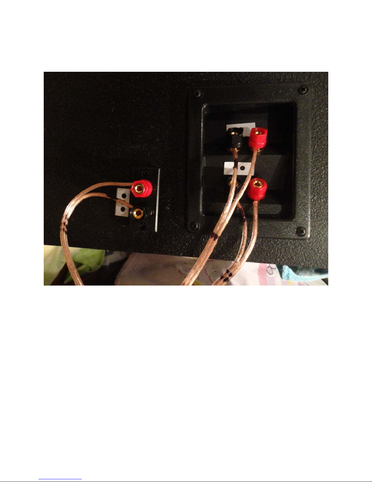
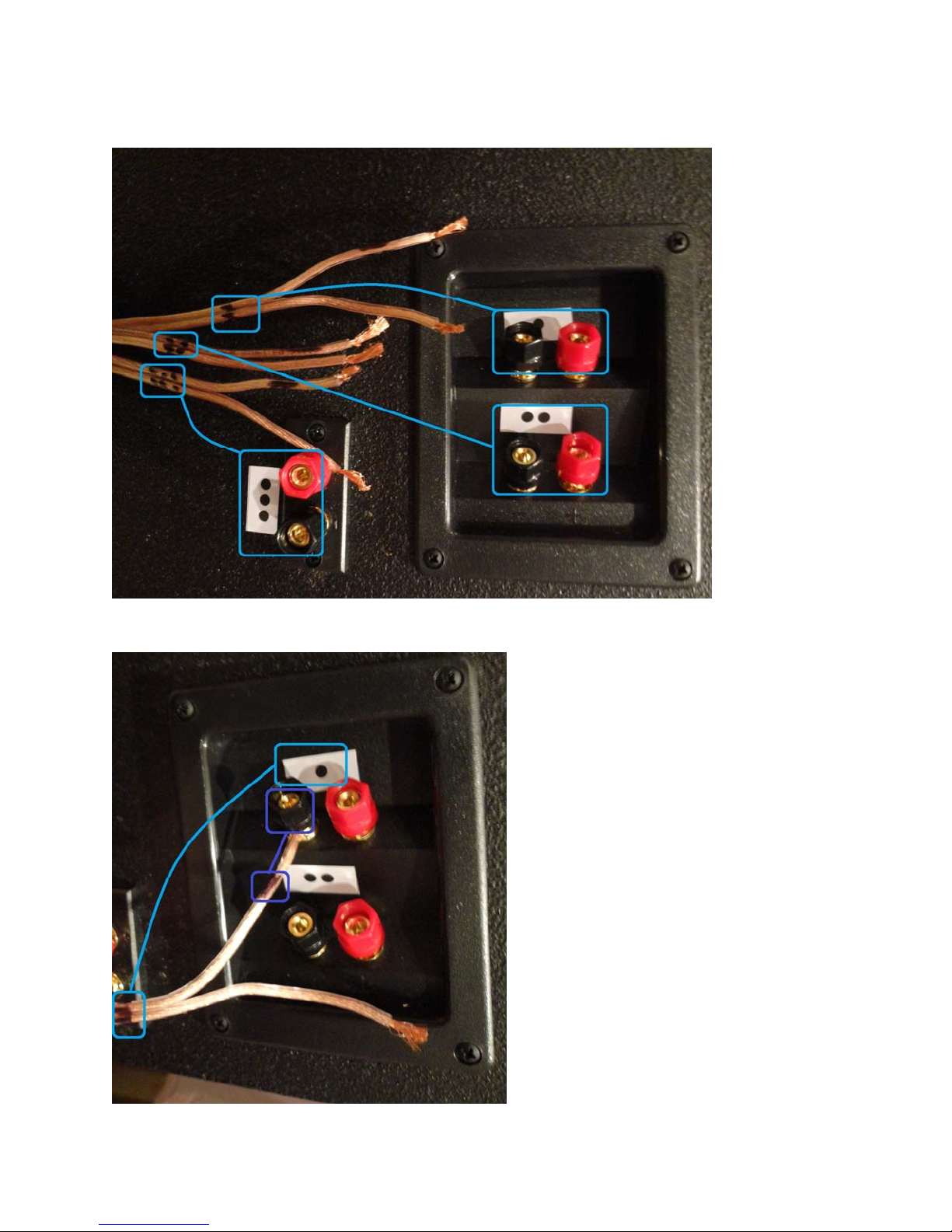
Make sure all loudspeaker cables (from amp to loudspeaker terminals) are connected properly before turning
on the amplifier. Make sure the cables are securely attached to loudspeaker’s input terminal. Permanent
damage to the amplifier may occur if the leads are touching each other while the amplifier is turned on.

LOUDSPEAKER FACE INFORMATION
LOUDSPEAKER SOUND DISPERSION
The optimum sound coverage for the device is shown in the pictures below.

ROOM PREPARATION
Loudspeaker and amplifier box dimensions can be seen below:
Add an extra 1.5in (38.1mm) extrusion to the box depth for the amplifier heat sink.

Please provide an appropriate size of a loudspeaker stand/base for the loudspeaker. Due to the low frequency
reproduction capability, vibration isolator/pad is recommended to be placed below the each loudspeaker box (between
the box and the stand).
Loudspeaker can be positioned in different setup. Please see description for different position in the following page.

Above picture shows the preferred setup. Woofers are located “inside” and loudspeaker is mounted horizontally. This
box position is the default position for E-33A-100701.
Above picture shows another variation of the horizontal position. Placing woofer “outside” may result in slightly
narrower stereo image.
This page shows two preferred setup. Please note that the tweeter is located on the top to avoid reflections from the
desk. If the loudspeaker is going to be mounted near the ceiling (close proximity to the ceiling wall), rotating the
loudspeaker so the tweeter located in the bottom is strongly recommended. Tweeter should be located as far as possible
from any boundaries.

As previously discussed, locating the tweeter near a boundary is not a good idea. We do not recommend this position.
Above picture shows the preferred position if the loudspeaker needs to be mounted vertically. Tweeter should be
placed “outside” and far from boundaries. If the tweeter is too high relative to the listening plane, please provide
down-tilt.
Placing the loudspeaker vertically will narrow the sound coverage (50° only).

LOUDSPEAKER CABLING
The correct connection of the cables to loudspeaker’s terminal is shown below:
Each cable is marked by dot (one, two or three) and each pair has one end that is marked by a black marker. The dot
on the cable corresponds to the dot on the sticker near the terminal. The black marker at the end of the cable
corresponds to the negative (black terminal) input.
Important Notice:
Please make sure the loudspeaker cable to each terminal does not have a tension at all time.
Make sure the copper for each cable is securely inserted to the terminal and tightly clamped.

Please see the picture below, showing the dot marker and connection detail:
Another closer look at the terminal cable is shown below:

The included cable from the amplifier to the loudspeaker is 1.5m / 6 ft long. If you want to replace or extend the
extension cable, please see the information below for the color code on the amplifier cable:
On the loudspeaker terminal: one dot is tweeter input terminal, two dots is 7 in midrange woofer input terminal and
three dots is 10 in subwoofer input terminal.

INPUT AND CONTROL
The amplifier does not have user control i.e. volume control, on/off button or preset buttons. It is highly recommended
to place the amplifier AC mains cable with a user controllable switch so it can be turned off if it is not used.
Input for the amplifier is one XLR cable. Please see the pictures below:
REMINDER: DO NOT TURN ON THE AMPLIFIER BEFORE CONNECTING AND SECURING ALL
LOUDSPEAKER CABLE TO THE APPROPRIATE INPUT TERMINAL.

MAXIMUM OUTPUT AND LISTENING DISTANCE
E-33A-100701 is optimized for 1-4m (3.3ft – 13ft) listening distance. It is not recommended to have a listening
distance of less than 1m (3.3ft).
The amplifier sensitivity is 1.4V RMS (5.1 dBu, 2V peak), therefore a 0.5V RMS pink noise with 12dB crest factor
(-3.8dBu, 2V peak) can be safely passed to the loudspeaker without clipping/distortion.
Using pink noise 12dB crest factor as a realistic program material replication, the calculated output (no weighting,
free-space, slow average) can be seen below.
Distance Output using 0.5V RMS Using 1V RMS (onset of
distortion
1m [3.3ft] 95 dB SPL 101 dB SPL
2m [6.6ft] 89 dB SPL 95 dB SPL
4m [13.1ft] 83 dB SPL 89 dB SPL
The acoustic output is also affected by other factors such as:
1. Different compression ratio/crest factor of the audio signal. A more compressed signal (smaller crest factor)
may result in higher SPL.
2. Room will add acoustical gain, up to 3dB.
Warning: The amplifier gain is set to unity! Always start with a low input signal [set the
master fader at -40dBFS or lower!]
QUICK DIGITAL OUTPUT ADJUSTMENT
A sound card/audio interface maximum output is usually rated in XX dBu (please consult to manufacture whether the
maximum output corresponds to 0 dBFS or other. For example: RME Fireface UFX monitor output is spec’d as follow:
Output level at 0dBFS @ 24dBu: +24dBu
This means at 0dBFS of the digital fader, using 24dBu mode, the maximum output is 24dBu. The nominal input of
the amplifier is -3.8dBu (≈ -4dBu), therefore the digital fader should not exceed -4 – 24 = -28 dBFS.
Another example is M-audio Audiophile 192 sound card which has a max output (balanced) of +14dBu (3.9VRMS).
To avoid clipping the master output fader should not exceed -4 – 14 = -18dBFS.
It is wise to start with a low output (-40dBFS or lower) and slowly raising the fader. If distortion starts to get noticeable
(although very little), the output is probably already 3dB or more too hot!
SURFACE CLEANING
Exterior box surface of may be cleaned using a lint-free cloth lightly damped with water. Please make sure to
disconnect the power cable from the amplifier. Do not use alcohol-based cleaners.
Driver surfaces (diaphragms and surrounds) may be cleaned using dry soft bristle brushes. The diaphragms are fragile
and easily damaged, please proceed with great care. Gently brush dust away from the surface.

THIRD PARTY ACCESSORIES
To further support the operation of E-33A-100701 loudspeaker, several third party accessories can be used such as:
1. Loudspeaker Stand
Please make sure the loudspeaker stand is able to support up to 27 kg (60 lbs). The base dimension should
not be too small. Example: Argosy X-Stand.
2. Vibration Isolator
Due to the low frequency reproduction capability of E-33A-100701, a vibration isolation between the
loudspeaker and the stand is highly recommended. Example: Auralex Mopad-XL, IsoAcoustics L8R430.
3. Power Strip with on/off control
The amplifier is not equipped with on/off switch. It is highly recommended to turn off the amp when it is not
used. A power strip/conditioner/surge protector with on/off switch is highly recommended. Example: Furman
product, SurgeX product.
4. Level control
The amplifier is always set a unity gain. A passive or active level control is recommended. Example: SM Pro
Audio Nano Patch+ (passive), Mackie BigKnob (Active), Coleman various level control products.
UNPACKING AND PACKING
Due to the size and weight of the loudspeaker, it is important to follow the following procedure/precautions while
unpacking:
1. Never try to lift the inner box from the outer box or lift the loudspeaker from the inner box.
2. Open one side of the box and flip the opening to face the floor (open end rests on the floor). Remove the
outer box by lifting it.
3. Do the same for the inner box: open one side of the box and flip the opening to face the floor (open end rests
on the floor). Remove the inner box by lifting it.
4. To ease the process, loose foams or other accessories can be removed prior to flipping the opening.
5. Due to the weight, it is wise to get a second person help to lift the loudspeaker.
If you need to repack the unit for shipment, the loudspeaker has to be prepared before placing it to the inner box. The
first step is standing the loudspeaker vertically so the 10in woofer is on the top as shown in the picture below.
The edge protection should be placed as shown in the picture, which creates
an air gap for all of the components. After all foams are taped, insert the box
from the top and then flip everything. Fill in the rest of the gaps using the
foams and edge protection. Seal the inner box and add the additional edge
protection before placing it to the outer box. When the box is moved/rotated,
no moving part should be heard from inside the box.
Warnings: small air gap in the front of the face/components are required to
avoid damage during shipment.
Table of contents