USER MANUAL - IM4.OP PROFESSIONAL 4 CHANNEL MIXER
PAGE 5
Cleaning the Appliance
Clean by wiping with a polished cloth slightly dipped with water. Avoid getting water inside the unit. Do not use volatile liquids such as
benzene or thinner which will damage the unit.
Use good quality cinch-cinch cables to prevent bad audio quality. (example: Hybrid+ code: 2-0370)
For more information on connections, please refer to the next chapter.
Be sure to turn off the unit before you make changes to the different connections.
In this manual we talk about “line inputs”. This is a global name for inputs with a level between 750mV and 2V. This includes tuners,
videos, CD-players, etc.
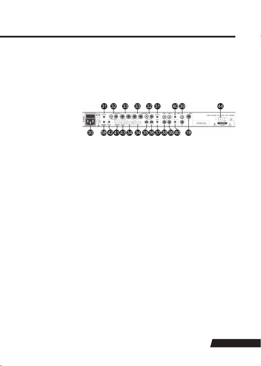
CONNECTIONS
FUNCTIONS FRONT
1. Microphone input: This is a balanced JACK-connector without phantom power provision, hence only suitable for dynamic micro
phones. You can connect the microphone on the front panel (1A) or back panel (1B).
2. Level control for microphone: adjusts the level of the mic input. To avoid mic feedback, please make sure that the level control is
closed before a mic is connected.
3. MIC. ON/OFF switch: Used to switch the connected mic on/off.
4. Microphone Equalizer: 2-Band tone controls with an adjustment range of ±12dB. Adjust the tone controls until you have optimal
sound without feedback noises.
5. Talkover adjustment: The talkover circuit make it possible to automatically damp the music while you speak into the microphone.
There are two controls to make sure that the talkover works as expected:
Talkover Damping (5A): adjusts the amount of damping once the talkover is active. If no talkover effect is required the
DAMPING control can be set to “off”.
Talkover Threshold (5B): adjusts when the talkover should start damping the music. The higher the setting, the faster the
talkover will come in action. Adjustments shall be made with a small screw driver. Do not apply excessive force with the screw
driver.
6. Aux/Line input: 3.5mm stereo jack that makes it easy to connect a portable audio player to the front panel of the unit.
7. Level control for line inputs: adjusts the input level of both 1 + 2 line inputs. The control range can be adjusted using the gain
controls on the back panel (41).
8. CUE switch for stereo channels: Sends the audio of the respective channel to the headphone bus for pre-fader listening (CUE) using
the headphone output (15). An LED indicates if the CUE-function is active.
9. Level control for internal player: adjusts the level to make a good balance between the levels of the line inputs and internal player.
10. Master 1 Equalizer: 2-Band tone controls for master 1 with an adjustment range of ±12dB.
11. Master 1 level control: controls the level of the different master 1 outputs: unbalanced (32), balanced
(33)and terminal block (34). The control range can be adjusted using the “max level” control on the back panel (31).
12. Master 2 level control: identical controls as for master 1 (11).
13. Master output level meter: Displays the output level set by the master1 level control (11). Note that the setting of Max. level control
(31) on the back panel does not affect the display of this meter.
14. CUE Volume: Sets the signal volume of the headphone output (15). Always set this control to minimum before putting on head
phones, as sudden high-volume impact may damage your ears.
15. Headphones output: a ¼” Jack connector to connect a headphone for monitoring. Turn the CUE volume (14) down before plugging in
any headphones.
16. USB memory socket: Insert a FAT32-formatted USB memory stick of max 16GB with a one level folder structure for replay of WMA,
WAV and MP3 files here. Note that this socket does NOT support USB hard drives, neither for memory size nor for
power require ments.
17. JINGLE buttons: Provided that the inserted media contains a folder named “Jingles” in its root directory, and that the files in this
folder follow certain naming conventions, up to 3 of these files can be activated by the Jingle buttons. When a jingle is activated, the
current program is muted and the jingle is played instead; however, the program progresses in the background. Jingles can be
played both in Media play mode and FM mode. A further scheduled jingle play mode is available by pressing the J1 (jingle 1) button
for longer than 2 seconds, the LED (18) will indicate that the scheduled jingle play mode is active. To de-activate the scheduled
jingle pay mode, press the J1 button again for more than 2 seconds. For more details, please see the chapter “Jingle player”.
Remark: after switching the unit off and on again, scheduled jingle playback must be activated again.
18. Scheduled Jingle Play LED: This LED is lit when the scheduled jingle play mode was activated by pressing the J1 button for longer
than 2 seconds.
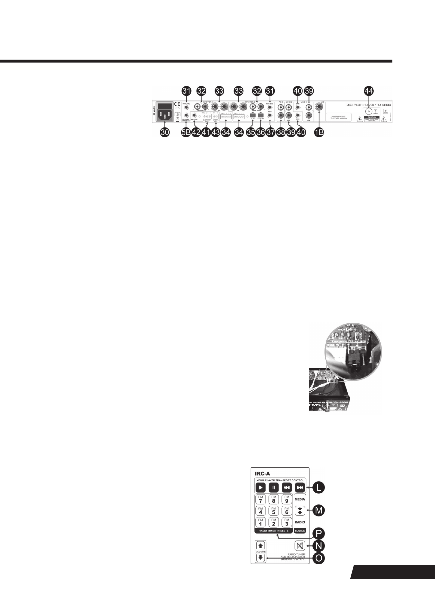
19. SOURCE button: Toggles the program source between Media play and FM-Tuner. If FM-Tuner is selected, the display’s FM Mode
indicator (H) is lit while the media replay related indicators (I, J, K) are disabled. Further the media replay related user interface
elements (22/23/26) are disabled and the functional assignment of the navigation controls (24/25) is changed.
20. Time Display selector: Selects between elapsed/remaining time display. The display shows [E] for Elapsed time or [R] for
Remaining time (see display “B” and “C”) and is always related to track currently playing.
This control is inactive in FM mode.