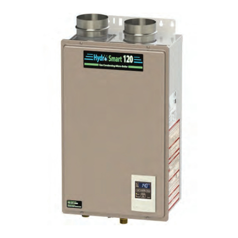
Hydro-Smart 115 User manual

‐Donotstoreorusegasolineorother
flammablevaporsandliquidsinthevicinityof
thisoranyotherappliance.
‐WHATTODOIFYOUSMELLGAS
Donottrytolightanyappliance.
Donottouchanyelectricswitch,donot
useanyphoneinyourbuilding.
Immediatelycallyourgassupplierfroma
neighbor'sphone.Followthegas
supplier'sinstructions.
Ifyoucannotreachyourgassupplier,call
thefiredepartment.
‐Installationandservicemustbeperformed
byaqualifiedinstaller,serviceagencyorthe
gassupplier.
Hydro‐Smart115
“MicroBoiler”forRadiantHeating
InstallationManualandOwner’sGuide
H
y
dro‐Smart115
Ifyouhaveanyquestions,please
callorwriteto:
Hydro‐SmartInc.
10725165thAveNW,
Elk River, MN 55330
WARNING
Iftheinformationinthese
instructionsisnotfollowed
exactly,afireorexplosion
mayresultcausing
propertydamage,personalinjuryordeath.
PleasemakesurethepropergaspressureguidelinesandrecommendationfromHydro‐
Smartfailuretodosocancauseafireorexplosionandmayresult,causingproperty
damage,personalinjury,ordeath.
ANSI Z21.10.3 andCSA4.3

Contents
2│Page
CONTENTS
SPECIFICATIONS…………………………………………………………………………………………..………………………...
INTRODUCTION…………………………………………………………………………………………………..………………….
SAFETYGUIDELINES…………….………………………………………………………………………………………..………..
INSTALLATION………………………………………………………………………………………………..…………………..….
General………………………………………………………………………………………………………………………..…..…
Clearances…………………………………………………………………………………………………………………………..
IncludedAccessories…………….………………………………………………………………………………………..…..
OptionalItems…………………………………………………………………………………………………………………….
WarningforInstallations…………………………………………………………………………………………………….
High‐AltitudeInstallations…………………………………………………………………………………………………..
VentingInstructions…………………………………………………………………………………………………………...
GasSupplyandGasPipeSizing………........................................................................................
WaterConnections……………..………………………………………………………………………………………………
ElectricalConnections……………………………………………………………………..…………………………….......
RemoteControllerConnections……..……………………………………………………………………….………..…
APPLICATIONS...………………………………………………………………………………………………………………..……
INITIALOPERATION..………………………………………………………………………………………………………….……
OPERATINGSAFETY…………………………………………………………………………………………………………………
NORMALOPERATION…………………………………………………………………………………………………………..…
General………..……….………….…………………………………………………………………………………………………
Operation……………………………………………………………………………………………………………………….....
TemperatureSettings.…….……..……………………………………………………………………………………………
Flow…………………………………………………………………………………………………………………………………….
FreezeProtectionSystem…….…………………………………………………………………………………………..…
MaintenanceandService………………………………………………………………………………………………….…
UnitDraining…………………………………………….…………………………………………………………………………
TROUBLESHOOTING……..……………………………………………………………………………………………………..…
General………..……….………….…………………………………………………………………………………………………
ErrorCodes.…………………….…..………………………………………………………………………………………………
COMPONENTSDIAGRAM……………………………………………………………………………………………………..…
PARTSLIST………………….………………………………………………………………………………………………..…………
OUTPUTTEMPERATURECHART…………………………………………………………………………………………...…
LIMITEDWARRANTY…………………………………………………………....…………………………………………….….
3
4
5
6
6
8
8
9
10
11
12
17
20
21
22
23
25
26
28
28
28
29
30
30
31
31
32
32
34
37
39
41
42
InstallationManual
Owner’sGuide

Specifications
3│Page
SPECIFICATIONS
ModelHydro‐Smart115
NaturalGasInput
(OperatingRange)
Min:19,500Btu/h
Max:140,000Btu/h
PropaneInput
(OperatingRange)
Min:19,500Btu/h
Max:140,000Btu/h
GasConnection¾”NPT
WaterConnections¾”NPT
WaterPressure15‐150psi*
NaturalGas
InletPressure
Min.5.0”WC
Max.10.5”WC
Propane
InletPressure
Min.8.0”WC
Max.14.0”WC
Manifold
Pressure**
Natural2.0”WC
Propane2.5”WC
Weight33lbs.
DimensionsH20.5”xW13.8”xD6.7”
IgnitionElectricIgnition
Electric
Supply120VAC/60Hz
Consumption
Operation73.1W/0.61A
Standby6.2W/0.05A
Freeze‐
Protection111W/0.93A
*40psioraboveisrecommendedformaximumflow.
**TheManifoldPressureisthefactorysettingandgenerallyshouldnotneedadjustment.
NOTE:
Checktheratingplatetoensurethisproductmatchesyourspecifications.
InaccordancewithANSIZ21.10.3,COemissiondoesnotexceed400PPMfor
normalinput.
Hydro‐Smartreservestherighttodiscontinue,orchangeatanytime,
specificationsordesignswithoutnoticeandwithoutincurringobligations.
I
I
I
n
n
n
s
s
s
t
t
t
a
a
a
l
l
l
l
l
l
a
a
a
t
t
t
i
i
i
o
o
o
n
n
n
M
M
M
a
a
a
n
n
n
u
u
u
a
a
a
l
l
l

Introduction
4│Page
INTRODUCTION
Thismanualprovidesinformationnecessaryfortheinstallation,operation,and
maintenanceofthewaterheater.
Themodeldescriptionislistedontheratingplatewhichisattachedtothefrontpanel
ofthewaterheater.
Pleasereadallinstallationinstructionscompletelybeforeinstallingthisproduct.
Ifyouhaveanyproblemsorquestionsregardingthisequipment,consultwithHydro‐
Smart.
Hydro‐Smart115isawaterheaterdesignedtobeusedwithradiantheatingina
combinationHydroPanel.
1. Ahotwatertapisturnedon.
2. Waterenterstheheater.
3. Thewaterflowsensordetectsthewaterflow.
4. Thecomputerinitiatesthefanmotorandsendsasignaltotheignitertocreateanignition
spark.
5. Thegasignitesandflamesappearwithintheburnerchamber.
6. Watercirculatesthroughtheheatexchangerandthengetshot.
7. Usingthermistorstomeasuretemperaturesthroughoutthewaterheater,thecomputer
modulatesthegasandwatervalvestoensureproperoutputwatertemperature.
8. Whentheta
p
isturnedoff
,
theunitshutsdown.
Theprinciplebehindtanklesswaterheatersissimple:
Pleasereadallinstallationinstructionscompletelybeforeinstallingthisproduct.
ThisproductisonlytobeusedwithHydro‐SmartHeatingPanels,“Integrator”.
*Thisdiagram
illustratestankless
waterheaterdesign
conceptsonlyand
doesnotaccurately
representtothewater
heater’sphysical
description.
Watersupply
Heatingpanel“Integrator” Strainer
Gasvalve
Thermistor
Burner
Hydro‐Smart115
GAS
Airvent
Expansiontank
Flowsensor
Watercontrolvalve
Pumpcontroller
Primarypump
Secondarypump
Radiantheating
Checkvalve

SafetyGuidelines
5│Page
Watertemperaturesover125°F (52
°
C) cancausesevereburnsinstantlyordeath
fromscalding.Thewatertemperatureissetat122°F(50°C)fromthefactoryto
minimizeanyscaldingrisk.Beforebathingorshoweringalwayscheckthewater
temperature.
Donotstoreorusegasolineorotherflammables,vapors,orliquidsinthevicinity
ofthisappliance.
Donotreversethewaterand/orgasconnectionsasthiswilldamagethegas
valvesandcancausesevereinjuryordeath.Followthediagramonp.20when
installingyourwaterheater.
Donotusethisapplianceifanyparthasbeenincontactwithorbeenimmersed
inwater.Immediatelycallalicensedplumber,alicensedgasfitter,ora
professionalservicetechniciantoinspectand/orservicetheunitifnecessary.
Donotdisconnecttheelectricalsupplyiftheambienttemperaturewilldrop
belowfreezing.TheFreezePreventionSystemonlyworksiftheunithaselectrical
power.Thewarrantywillnotbecoverediftheheatexchangerisdamageddueto
freezing.RefertothesectionontheFreezePreventionSystemonp.30formore
information.
SAFETYGUIDELINES
SAFETYDEFINITIONS
Indicatesanimminentlyhazardoussituationwhich,ifnotavoided,willresultin
deathorseriousinjury.
Indicatesanimminentlyhazardoussituationwhich,ifnotavoided,couldresult
indeathorseriousinjury.
Indicatesanimminentlyhazardoussituationwhich,ifnotavoided,couldresult
inminorormoderateinjury.
GENERAL
1. Followalllocalcodes,orintheabsenceoflocalcodes,followthemostrecenteditionofthe
NationalFuelGasCode:ANSIZ223.1/NFPA54intheUSAorCAN/CSAB149.1NaturalGas,Propane
InstallationCodeinCanada.
2. Properlygroundtheunitinaccordancewithalllocalcodesorintheabsenceoflocalcodes,with
theNationalElectricalCodes:ANSI/NFPA70intheUSAorCSAstandardC22.1CanadaElectrical
CodePart1inCanada.
3. Carefullyplanwhereyouintendtoinstallthewaterheater.Pleaseensure:
Yourwaterheaterwillhaveenoughcombustibleairandproperventilation.
Locateyourheaterwherewaterleakagewillnotdamagesurroundingareas(pleaserefer
top.7).
4. ChecktheratingplateforthecorrectGASTYPE,GASPRESSURE,WATERPRESSUREandELECTRIC
RATING.
*Ifthisunitdoesnotmatchyourrequirements,donotinstallandconsultwithHydro‐Smart.
5. Ifanyproblemshouldoccur,turnoffallhotwatertapsandturnoffthegas.Thencallatrained
technicianortheGasCompanyorHydro‐Smart.
WARNING
CAUTION
DANGER
WARNING

Installation
6│Page
INSTALLATION
GENERAL
1. Followalllocalcodes,orintheabsenceoflocalcodes,followthemostrecenteditionofthe
NationalFuelGasCode:ANSIZ223.1/NFPA54intheUSAorCAN/CSAB149.1NaturalGas,
PropaneInstallationCodeinCanada.
2. Allgaswaterheatersrequirecarefulandcorrectinstallationtoensuresafeandefficient
operation.Thismanualmustbefollowedexactly.Readthe“SafetyGuidelines”section.
3. Themanifoldgaspressureispresetatthefactory.Itiscomputercontrolledandshouldnot
needadjustment.
4. Maintainproperspaceforservicing.Installtheunitsothatitcanbeconnectedorremoved
easily.RefertotheClearancesSectiononp.8forproperclearances.
5. Thewaterheatermustbeinstalledinalocationwheretheproperamountofcombustibleair
willbeavailabletoitatalltimeswithoutobstructions.
6. Theelectricalconnectionrequiresameansofdisconnection,toterminatepowertothewater
heaterforservicingandsafetypurposes.
7. Donotinstalltheunitwheretheexhaustventispointingintoanyopeninginabuildingorwhere
thenoisemaydisturbyourneighbors.Makesuretheventterminationmeetstherequired
distancebylocalcodefromanydoorwayoropeningtopreventexhaustfromenteringabuilding
(refertop.15).
8. Particlesfromflour,aerosols,andothercontaminantsmayclogtheairventorreducethe
functionsoftherotatingfanandcauseimproperburningofthegas.Regularlyensurethatthe
areaaroundtheunitisdust‐ordebris‐free;regularmaintenanceisrecommendedforthese
typesofenvironment.
9. Ifyouwillbeinstallingthewaterheaterinacontaminatedareawithahighlevelofdust,sand,
flour,aerosolsorothercontaminants/chemicals,theycanbecomeairborneandenterandbuild
upwithinthefanandburnercausingdamagetothewaterheater.
10. FortheHydro‐Smart115:
Theseunitsmaybeconvertedtoadirect‐vent(sealedcombustion)appliancebyinstallinga
direct‐ventconversionkitPartNo.9007667005(TK‐TV10)whichwillbringinallrequired
combustibleairfromoutsidethebuilding.Wheninstallingthedirect‐ventconversionkit,
pleasefollowallinstructionsincludedwiththekit.
Ifthewaterheaterisusedasadirect‐ventappliance,theunitrequiresa3”combustibleair
supplypipe.Theintakepipemustbesealedairtight.AirsupplypipecanbemadeofABS,
PVC,galvanizedsteel,corrugatedaluminum,corrugatedstainlesssteelorCategoryIII
stainlesssteel.
Terminatingtheventingthroughasidewallisrecommendedforthedirect‐ventsystem.
Runningtheexhaustventandtheintakepipeparallelisrecommended.
Terminatingtheexhaustandintakeonthesamewall/surfaceisrecommended.
Terminatinginthesamepressurezoneallowsforpressurebalancing,whichprevents
nuisanceshutdowns.

Installation
7│Page
Installationandservicemustbeperformedbyaqualifiedinstaller(for
example,alicensedplumberorgasfitter),otherwisethewarrantybyHydro‐
Smartwillbevoid.
Theinstaller(licensedprofessional)isresponsibleforthecorrectinstallation
ofthewaterheaterandforcompliancewithallnational,state/provincial,
andlocalcodes.
Hydro‐Smartdoesnotrecommendinstallingthewaterheaterinapitor
locationwheregasandwatercanaccumulate.
Donothavetheventterminalpointingtowardanyoperatingwindow,door,or
openingintoabuilding.
Donotinstallnexttoanysourceofairbornedebris,suchasaclothesdryer,
thatcancausedebristobetrappedinsidethecombustionchamber,unless
thesystemisdirect‐vented.
Hydro‐Smartdoesnotrecommendinstallingthewaterheaterinanatticdue
tosafetyissues.Ifyouinstallthewaterheaterinanattic:
Makesuretheunitwillhaveenoughcombustionairandproperventilation.
Keeptheareaaroundthewaterheaterclean.Whendustcollectsonthe
flamesensor,thewaterheaterwillshutdownonanerrorcode.
Iftheaboveconditionscannotbemet,usethedirectventconversionkit
PartNo.9007667005(TK‐TV10).
Placetheunitforeasyaccessforserviceandmaintenance.
Adrainpan,orothermeansofprotectionagainstwaterdamage,is
re
q
uiredtobeinstalledunderthewaterheaterincaseofleaks.
Thewarrantywillnotcoverdamagecausedbywaterquality.
Onlypotablewaterorpotablewater/glycolmixturescanbeusedwiththis
waterheater.Donotintroducepoolorspawater,oranychemically
treatedwaterintothewaterheater.
Waterhardnesslevelsmustnotexceed7grainspergallon(120ppm)for
singlefamilydomesticapplicationsormorethan4grainspergallon(70
ppm)forallothertypesofapplications.Waterhardnessleadstoscale
formationandmayaffect/damagethewaterheater.Hardwaterscaling
mustbeavoidedorcontrolledbyproperwatertreatment.
WaterpHlevelsmustbebetween6.5and8.5
Wellwatermustbetreated.
Donotinstalltheunitwherewater,debris,orflammablevaporsmaygetinto
theflueterminal.
Hydro‐Smartrecommendsusingthedirectventkitwhenthewaterheateris
installedinabeautysalon.Somechemicalsusedinabeautysalonmayaffect
theflamesensor.Waterheatermaynotworkproperly.
Althoughthewaterheaterisdesignedtooperatewithminimalsound,Hydro‐
Smartdoesnotrecommendinstallingtheunitonawalladjacenttoa
bedroom,oraroomthatisintendedforquietstudyormeditation,etc.
Locateyourheaterclosetoadrainwherewaterleakagewillnotdodamageto
surroundingareas.Aswithanywaterheatingappliance,thepotentialfor
leakageatsometimeinthelifeoftheproductdoesexist.Hydro‐Smartwill
notberesponsibleforanywaterdamagethatmayoccur.Ifyouinstalladrain
panundertheunit,ensurethatitwillnotrestrictthecombustionairflow.
CAUTION
WARNING

Installation
8│Page
CLEARANCES
ModelTopBottomFrontBackSides
Hydro‐Smart115*12”12”24”1”2“
*Standardindoorinstallationsanddirect‐ventindoorinstallationshavethesameclearances.
INCLUDEDACCESSORIES
Checkthattheseitemsbelowareincludedwiththewaterheater.
1.InstallationManualand
Owner’sGuide
2.
ProductRegistrationCard
3.Remotecontroller
900766605(TK‐RE02)
OPTIONALITEMS
ModelHydro‐Smart115
9007678005(TK‐BF01) ✔
9007667005(TK‐TV10) ✔
9007671005(TK‐PCJr2) ✔
9007608005(TK‐KPWL4)
9007609005(TK‐KPWH4) ✔
9007680005(TK‐KPCT43) ✔
Bottom
Side
Top
Side
Front
Back
Maintainallclearancesaround
thewaterheater.
Qty:1Qty:1Qty:1

Installation
9│Page
1.BackflowPreventer:9007678005(TK‐BF01)
TheBackflowpreventerprevents
thebackflowofairthroughthe
exhaustvent.Thishelpsprevent
harmfulexhaustgasesfrom
enteringthehome,aswellas
helpingtopreventtheunitfrom
freezinginareaswherecoldaircanbeblown
ordrawnintotheexhaustsystem.Installthis
ventdamperinaccordancewiththe
installationinstructionsandanyapplicable
codes.
2.Direct‐VentConversionKit:9007667005
(TK‐TV10)
Thiskitcanbeusedto
convertthewater
heaterfromastandard
ventsystemtoa
direct‐vent(orsealed
combustion)system.
Installthisconversionkitinaccordancewith
theinstallationinstructionsandanyapplicable
codes.
3.PipeCovers:9007671005(TK‐PCJr2)
Thepipecoverprotectstheplumbingpipestothewaterheaterfromunexpected
adjustments.Thispipecoverisfixedtothebottomofthewaterheater,whichhides
theplumbingandimprovesthevisualaspectsofthewholeinstallationforthewater
heater.
4.T‐VentWallThimblewithTermination:9007608005(TK‐KPWL4)and9007609005(TK‐KPWH4)
Theseterminationsareusedwhenventingoutthroughthewall
andarecompatiblewiththeT‐Ventpipesystem.
Theseterminationsarespecialstainlesssteelventsforgas
appliancesandareULlistedasCategoryII,IIIandIV.Thereare
twotypesofterminations:theLouverterminationandtheHood
termination.Fordifferentwallthicknesses,therearetworanges
oflengthsavailable(refertotheventingbrochurefordetails).
Installtheseventterminationsinaccordancewiththeir
installationinstructionsandanyapplicablelocalcodes.
5.Direct‐VentConcentricTermination:9007680005(TK‐KPCT43)
Usedwhenterminatingdirect‐vent(sealed‐combustion)systems,
withdirect‐ventmodelsthatrequirea3”intakeanda4”exhaust.
Thisconcentricterminationprovidestheconvenienceofonly
havingtomakeonepenetrationthroughasidewallinsteadoftwo
separatepenetrationsfortheintakeandexhaustpiping.The
terminationincludesabirdscreen,restrictingsmallanimals,
pests,andforeignobjectsfromenteringintotheventsystem.
Thissidewallterminationisavailableinthreedifferentsizes,to
coverallrangesofwallthicknesses.
Direct‐ventConcentricTermination
Part#Coveringwallthickness
9007680005(TK‐KPCT43‐1)3.9”–7.1”
9007772005(TK‐KPCT43‐2)6.9”–10.1”
9007773005(TK‐KPCT43‐3)9.8”–13.0”
Louver
Termination
9007608005
(TK‐KPWL4)
Hood
Termination
9007609005
(TK‐KPWH4)

Installation
10│Page
WARNINGFORINSTALLATIONS
FORYOURSAFETY,READBEFOREINSTALLATION:
DonotinstalltheHydro‐Smart115wherewater,
debrisorflammablevaporsmaygetintotheflue
terminal.ThismaycausedamagetotheHydro‐
Smart115andvoidthewarranty.
Donotinstallnexttoadryeroranysourceof
airbornedebristhatcanbetrappedinsidethe
combustionchamber,unlessthesystemisdirect
vented.
Hydro‐Smart115isprohibitedandnot
recommendstobeinstalledinanatticdueto
safetyissues.
FORYOURSAFETY,READBEFOREINSTALLATION:
Prohibited
Prohibited

Installation
11│Page
HIGH‐ALTITUDEINSTALLATIONS
Checktheelevationwhereyourwaterheaterisinstalled.Setdipswitchesshowninthetablebelow
dependingonthealtitude.
Altitude0to2,000ft
(DEFAULT)2,000to4,000ft 4,000to6,000ft Over6,000ft
SwitchNo.3OFFON OFF
Consult
Hydro‐Smart
at763‐
331‐3066
SwitchNo.4OFFOFFON
OFF
ON12345678
OFF
ON12345678
OFF
ON12345678
WARNING
Thedarksquaresindicatethe
directionthedipswitchesshould
besetto.
Dipswitches

Installation
12│Page
Improperventingofthisappliancecanresultinexcessivelevelsofcarbon
monoxidewhichcanresultinseverepersonalinjuryordeath.
Improperinstallationcancausenauseaorasphyxiation,severeinjuryordeathfrom
carbonmonoxideandfluegasespoisoning.Improperinstallationwillvoidproduct
warranty.
Wheninstallingtheventsystem,allapplicablenationalandlocalcodesmustbe
followed.Ifyouinstallthimbles,firestopsorotherprotectivedevicesandthey
penetrateanycombustibleornoncombustibleconstruction,besuretofollowall
applicablenationalandlocalcodes.
VENTINGINSTRUCTIONS
‐General‐
Thewaterheatermustbeventedinaccordancewiththesection“VentingofEquipment"ofthelatest
editionoftheNationalFuelGasCode:ANSIZ223.1/NFPA54intheUnitedStatesand/orSection7ofthe
CAN/CSAB149.1NaturalGasandPropaneInstallationCodeinCanada,aswellasapplicablelocal
buildingcodes.
Hydro‐Smartrecommendsthe“T‐Vent”linemanufacturedbyTAKAGI(Referto“T‐Vent”brochurefor
details).However,thefollowingarealsoULlistedmanufacturers:ProTechSystemsInc.(FasNSeal),Flex‐
LInc.,Z‐FlexInc.(Z‐VentIII),Metal‐FabInc.,andHeat‐FabInc.(Saf‐TVent).
Generalrulesforventingwaterheatersare:
Placethewaterheaterascloseaspossibletotheventterminator.
Theventcollarofthewaterheatermustbefasteneddirectlytoanunobstructedventpipe.
Donotweldtheventpipetothewaterheater’sventcollar.
Donotcuttheventcollaroftheunit.
Theventmustbeeasilyremovablefromthetopofthewaterheaterfornormalserviceand
inspectionoftheunit.
Thewaterheaterventmustnotbeconnectedtoanyothergasapplianceorventstack.
Avoidusinganoversizedventpipeorusingextremelylongrunsofthepipe.
Forrooftopventing,araincaporotherformofterminationthatpreventsrainwaterfrom
enteringintothewaterheatermustbeinstalled.
Donotcommonventorconnectanyventfromotherappliancestothewaterheatervent.
Generalrulesforventterminations:
Avoidlocatingthewaterheaterventterminatornearanyairintakedevices.Thesefanscan
pickuptheexhaustflueproductsfromthewaterheaterandreturnthemtothebuilding.
Thiscancreateahealthhazard.
Locatetheventterminatorsothatitcannotbeblockedbyanydebris,atanytime.Most
codesrequirethattheterminatorbeatleast12inchesabovegrade,buttheinstallermay
determineifitshouldbehigherdependingonthejobsiteconditionandapplicablecodes.
Apropersidewallterminatorisrecommendedwhenthewaterheaterisventedthrougha
sidewall.
Regardingtheclearancesfromtheexhaustterminatortotheairinletoropening,referto
thenextfewpages.
CAUTION
DANGER

Installation
13│Page
‐Exhaustventing‐
ThisisaCategoryIIIapplianceandmustbeventedaccordingly.Theventsystemmustbesealedairtight.
AllseamsandjointswithoutgasketsmustbesealedwithhighheatresistantsiliconesealantorULlisted
aluminumadhesivetapehavingaminimumtemperatureratingof350°F.Forbestresults,aventsystem
shouldbeasshortandstraightaspossible.
ThiswaterheaterisaCategoryIIIapplianceandmustbeventedaccordinglywithany4”vent
approvedforusewithCategoryIIIorSpecialBHtypegasvent.
Followtheventpipemanufacturer’sinstructionswheninstallingtheventpipe.
Donotcommonventthisappliancewithanyotherventedappliance(Donotterminatevent
intoachimney.Iftheventmustgothroughthechimney,theventmustrunalltheway
throughthechimneywithCategoryIIIapprovedorSpecialBHventpipe).
Whenthehorizontalventrunexceeds5ft.,supporttheventrunat3ft.intervalswith
overheadhangars.
Themaximumlengthofexhaustventpipingmustnotexceed50ft.(deducting5ft.foreach
elbowusedintheventingsystem).Donotusemorethan5elbows.
DiameterMax.No.ofElbowMax.VerticalandHorizontal(Total)VentLength
4”550ft.
*Foreachelbowadded,deduct5ft.frommax.Ventlength.
No.ofElbowsMax.VerticalorHorizontalLength
050ft.
145ft.
240ft.
525ft.
‐VentingIllustrations‐
HorizontalInstallationDiagramVerticalInstallationDiagram
SidewallVent
Terminator
Wall
BackflowPreventer*
VerticalCondensationDrain**
Fordetailsoftheoptionalitems,refertotheInstallationmanualforeachOptionalitem.
Roo
f
VerticalCondensation
Drain**
RoofFlashing
RainCap
BackflowPreventer*

Installation
14│Page
*BackflowPreventer (Recommendedforfreezingweatherconditions:36
°
Fandbelow)
**VerticalCondensationDrainmustbeinstalledaccordancewithlocalcodes.
HorizontalInstallationDiagram
WithDirect‐VentConcentric
Termination
HorizontalInstallationDiagram
(Withdirect‐venting)
VerticalInstallationDiagram
(Withdirect‐venting)
Thewaterheater
Intakeportof
Direct‐Vent
ConversionKit
InstallationDiagramofDirect‐Vent
ConversionKitwithwaterheater
Wall
Direct‐vent
Concentric
Termination
PlateofDirect‐VentConversionKit
Seethepicturebelowfordetailedconnection
instructionstotheDirect‐VentConversionKit.
VerticalCondensationDrain**
Backflow
Preventer*
Wall
Sidewall
Vent
Terminator
RoofFlashing
Vertical
Condensation
Drain**
Backflow
Preventer*
RainCap
Roo
f
Firestop

Installation
15│Page
‐Ventterminationclearances‐
Canada U.S.A
Directventand
otherthanDirect
Vent
Directvent OtherthanDirectVent
AClearanceabovegrade,veranda,porch,deck,
orbalcony.1foot1foot1foot
BClearancetowindowordoorthatmaybe
opened.3feet1foot
4feetfrombeloworside
opening.1footfrom
aboveopening.
CClearancetopermanentlyclosedwindow * * *
D
Verticalclearancetoventilatedsoffitlocated
abovetheventterminatorwithinahorizontal
distanceof2feet(61cm)fromthecenterline
oftheterminator.
***
EClearancetounventilatedsoffit* * *
FClearancetooutsidecorner* * *
GClearancetoinsidecorner* * *
HClearancetoeachsideofcenterlineextended
abovemeter/regulatorassembly3feet**
IClearancetoserviceregulatorventoutlet. 3feet * *
J
Clearancetonon‐mechanicalairsupplyinlet
tobuildingorthecombustionairinlettoany
otherapplication.
3feet1foot
4feetfrombeloworside
opening.1footfrom
aboveopening.
KClearancetomechanicalairsupplyinlet. 6feet 3feet 3feet
LClearanceabovepavedsidewalkorpaved
drivewaylocatedonpublicproperty.7feet*7feet
MClearanceunderveranda,porchdeck,or
balcony.1foot**
*ForclearancesnotspecifiedinANSIZ223.1/NFPA54orCAN/CSA‐B149.1,pleaseuseclearancesinaccordancewith
localinstallationcodesandtherequirementsofthegassupplier.

Installation
16│Page
Pleasefollowalllocalandnationalcodesinregardstoproperterminationclearances.
Intheabsenceofsuchcodes,thefollowingclearancescanbeusedasguidelines.Local
codessupersedetheseguidelines.
Forsidewallterminations
Exhausttermination
1ft.
1ft.2ft.
Inside
corner
Formultiplesidewallexhaust
terminations(e.g.multi‐unit
systems),anexhausttermination
mustbeatleast1ft.awayfrom
anotherexhausttermination.An
exhaustterminationmustalsobe
atleast2ft.awayfromaninside
corner(iftheadjacentwallisless
than2ft.oflength,theminimum
requireddistanceawayfromthe
insidecornerwillbeequaltothe
lengthofthatadjacentwall).
Fordirect‐ventsidewall
terminationsthatusetwo
separatepenetrationsforthe
intakeandexhaust,distance
theintakeandexhaust
terminationsatleast3ft.away
fromeachother,nomatterthe
orientation.
Formultiple‐unit,direct‐ventsidewall
terminationsthatcombinetheintake
andexhaustintoasinglepenetration,
spaceeachdirect‐ventterminationat
least1ft.awayfromeachother,no
mattertheorientation.Adirect‐vent
terminationmustalsobeatleast2ft.
awayfromaninsidecorner(ifthe
adjacentwallislessthan2ft.of
length,theminimumrequired
distanceawayfromtheinsidecorner
willbeequaltothelengthofthat
adjacentwall).
Formultiple‐unitrooftopterminations(whetherforstandardindooror
direct‐ventinstallations)spaceallexhaustandintaketerminationsin
accordancewithlocalcodes.Anexhaustterminationmustbespacedfrom
awallorsurfaceinaccordancewithlocalcodesaswell.Intheabsenceof
suchacode,anexhaustterminationmustbeahorizontaldistanceofat
least2ft.awayfromawallorsurface.
A:Inaccordancewithlocalcodes
Forrooftopterminations
Airintake
Exhausttermination
A
A
A
A
A
2ft.
Airintake
Exhaust
termination
Exhaustand/ordirect‐vent
sidewallterminationsshould
beatleast2ft.awayfroman
oppositesurface/wall.Do
notplacethetermination
directlyinfrontofan
openingintoabuilding.
2ft.
Exhaust
termination
Airsupplyinlet
3ft.
3ft.
3ft.
Directventtermination
1ft.
1ft.
Inside
corner
2ft.
CAUTION

Installation
17│Page
Sizethegaspipeappropriatelytosupplythenecessaryvolumeofgasrequiredfor
thewaterheaterusingANSI233.1/NFPA54intheUSAorCAN/CSAB149.1inCanada
orlocalcodes.Otherwise,flowcapabilitiesandoutputtemperatureswillbelimited.
Checkthatthetypeofgasmatchestheratingplatefirst.
Ensurethatanyandallgasregulatorsusedareoperatingproperlyand
providinggaspressureswithinthespecifiedrangeshownbelow.Excessgas
inletpressuremaycauseseriousaccidents.
Conversionofthisunitfromnaturalgastopropaneorviseversawillvoidall
warranty.Contactyourlocaldistributortogetthecorrectunitforyourgas
type.Themanufacturerisnotliableforanypropertyand/orpersonal
damageresultingfromgasconversions.
GASSUPPLYANDGASPIPESIZING
‐General‐
Theminimumandmaximuminletgaspressuresare:
GastypeInletgaspressure
NaturalGasMin.5.0”WC–Max.10.5”WC
PropaneMin.8.0”WC–Max.14.0”WC
Gaspressureabovethisspecifiedrangeforthewaterheaterand/orinsufficientgasvolumewill
adverselyaffectperformance.Thesepressuresaremeasuredwhenthewaterheaterisinfull
operation.
Inletgaspressuremustnotexceedtheabovemaximumvalues;gaspressureabovethespecified
rangewillcausedangerousoperatingconditionsanddamagetotheunit.
Untiltestingofthemaingaslinesupplypressureiscompleted,ensurethegaslinetothewater
heaterisdisconnectedtoavoidanydamagetothewaterheater.
‐Gasconnections‐
1. Installamanualgasshut‐offvalvebetweenthewaterheaterandthegassupplyline.
2. Whenthegasconnectionsarecompleted,itisnecessarytoperformagasleaktest(seebelow)
eitherbyapplyingsoapywatertoallgasfittingsandobservingforbubblesorbyusingagasleak
detectiondevice.
Thewaterheateranditsindividualshutoffvalvemustbedisconnectedfromthegassupply
pipingsystemduringanypressuretestingofthatsystemattestpressuresinexcessof1/2psi
(3.5kPa).
Thewaterheatermustbeisolatedfromthegassupplypipingsystembyclosingitsindividual
manualshutoffvalveduringanypressuretestingofthegassupplypipingsystemattest
pressuresequaltoorlessthan1/2psi(3.5kPa).
3. Alwayspurgethegaslineofanydebrisand/orwaterbeforeconnectingtothegasinlet.
WARNING
NOTICE

Installation
18│Page
‐NaturalGasSupplyPiping‐
MaximumDeliveryCapacityofCubicFeetofGasperHourofIPSPipeCarryingNaturalGasof0.60SpecificGravity
BasedonPressureDropof0.5”WC
BasedonEnergyContentof1,000BTU/CubicFt.:Thewaterheaterrequires140CubicFt./hr.
Unit:CubicFeetperHour
PipeSizeLength
Diameter10’20’30’40’50’60’70’80’90’100’125’150’ 200’
¾”363249200171152138127118111104938472
1”684470377323286259239222208197174158 135
1¼”1,404965775663588532490456428404358324 278
1½”2,1031,445 1,161993 880 798 734 683 641 605536486 416
2”4,0502,784 2,2351,913 1,696 1,536 1,413 1,315 1,2341,1651,033 936 801
‐Propane(LP)SupplyPiping‐
MaximumCapacityofPropane(LP)Basedon11”WCsupplypressureata0.5”WCpressuredrop
Unit:kBTUperHour
PipeSize
Length
Diameter
10’20’30’40’50’60’70’80’90’100’125’150’ 200’
¾”567393315267237217196185173162146132112
1”1,071732590504448409378346322307275252213
1¼”2,2051,4961,2121,039913834771724677630567511440
1½”3,3072,2991,8581,5591,417 1,275 1,181 1,086 1,023 976866787675
2”6,2214,3313,4652,9922,646 2,394 2,205 2,047 1,921 1,8111,6061,496 1,260
Formoreinformation,pleaseseethebelow.
BasedonEnergyContentof1,000BTU/CubicFt:
Divideeachappliance’sBTUrequirementby1,000BTUtoget
theappliancesCubicFt.requirement.
Takeintoaccountthedistancetheapplianceisfromthegas
meter,lookintheabovegascharttoproperlysizetheline.
Forsectionsofthegaslinesupplyinggastomorethanone
appliance(Ex:PointAtoPointB),addupthecubicft.
requirementsoftheappliancesthatarebeingsuppliedbythat
section,andsizetothefarthestappliance.
ForExample:ThesectionfromAtoBsuppliesgastothe
furnace,range,anddryer.AddinguptheBTUrequirements
anddividingby1,000yieldsacubicft.requirementof220
cubicft.ofgas.Thefarthestapplianceistherange,whichis50
ft.awayfromthemeter.Lookingattheabovechart,and
underthecolumnof50ft.,SectionAtoBneedstobe1”in
ordertosupply220cubicft.
10’Length
1”PipeSizeC
GasSizingExample
(NaturalGas)
10’Length
3/4”PipeSize
15’Length
1/2”PipeSize
10’Length
1/2”PipeSize
Furnace
120,000BTU
Water
Heater
199,000BTU
5’Length
1‐1/4”PipeSize
Range
65,000BTU
10’Length
3/4”PipeSize
Dryer
35,000BTU
15’Length
1”PipeSize
5’Length
1‐1/4”PipeSize
GasMeter
B
A

Installation
19│Page
1. Turnoffallelectricpowertothewaterheaterifserviceistobeperformed.
2. Turnthemanualgasvalvelocatedontheoutsideoftheunitclockwiseto
theoffposition.
‐Measuringinletgaspressure‐
Thewaterheatercannotperformproperlywithoutsufficientinletgaspressure.Belowareinstructions
onhowtochecktheinletgaspressure.THISISONLYTOBEDONEBYALICENSEDPROFESSIONAL.
1. Shutoffthemanualgasvalveonthesupplygasline.
2. Removethescrewforthepressureportlocatedon
thegasinletofthewaterheatershowninthe
diagramtotheright.
3. Connectthemanometertothepressureport.
4. Re‐openthemanualgasvalve.Checktoseethat
therearenogasleaks.Opensomeofthefixtures
thatusethehighestflowratetoturnonthewater
heater.
5. Checktheinletgaspressure.Whenthewaterheater
isonmaximumburn,themanometershouldread
from5.0”to10.5”WCforNaturalgas,from8.0”to
14.0”WCforPropane.
Pressureport

Installation
20│Page
Donotusethiswaterheaterifanyparthasbeensubmersedunderwater.
Immediatelycallalicensedprofessionaltoinspectthewaterheatertoreplace
anydamagedparts.
Donotreversethehotoutletandcoldinletconnectionstothewaterheater.
Thiswillnotproperlyactivatethewaterheater.
WATERCONNECTIONS
Allpipes,pipefittings,valvesandothercomponents,includingsolderingmaterials,mustbesuitablefor
potablewatersystems.
1. Amanualshutoffvalvemustbeinstalledonthecoldwaterinlettothewaterheaterbetween
themainwatersupplylineandthewaterheater.
2. Inaddition,amanualshutoffvalveisalso
recommendedonthehotwateroutletofthe
unit.Ifthewaterheaterisinstalledwithin,or
subjectedto,aclosedloopwatersystem,a
thermalexpansiontankmustbeinstalled.
3. Beforeinstallingthewaterheater,flushthe
waterlinetoremovealldebris,andafter
installationiscomplete,purgetheairfromthe
line.Failuretodosomaycausedamagetothe
heater.
4. Thereisawirewithinthecoldinlettotrap
debrisfromenteringyourheater.Thiswillneed
tobecleanedperiodicallytomaintainoptimum
flow.
‐Pressurereliefvalve‐
Thewaterheaterhasahigh‐temperatureshutoffswitchbuiltinasastandardsafetyfeature(calleda
Hi‐Limitswitch)thereforea“pressureonly”reliefvalveisrequired.
Thisunitdoesnotcomewithanapprovedpressurereliefvalve.
Anapprovedpressurereliefvalvemustbeinstalledonthehotwateroutlet.
ThepressurereliefvalvemustconformtoANSIZ21.22orCAN1‐4.4andinstallationmustfollow
localcode.
Thedischargecapacitymustbeatleast140,000BTU/h.
Thepressurereliefvalveneedstoberatedforamaximumof150psi.
Thedischargepipingforthepressurereliefvalvemustbedirectedsothatthehotwatercannot
splashonanyoneoronnearbyequipment.
Attachthedischargetubetothepressurereliefvalveandruntheendofthetubetowithin6"
fromthefloor.Thisdischargetubemustallowfreeandcompletedrainagewithoutany
restrictions.
Ifthepressurereliefvalveinstalledonthewaterheaterdischargesperiodically,thismaybedue
toadefectivethermalexpansiontankordefectivepressurereliefvalve.
Thepressurereliefvalvemustbemanuallyoperatedperiodicallytocheckforcorrectoperation.
Novalvemustbeplacedbetweenthereliefvalveandthewaterheater.
Pressure
ReliefValve
Hot
outlet
Cold
inlet
Gas
inlet
AsCloseas
Possible
CAUTION
Table of contents
Other Hydro-Smart Boiler manuals
Popular Boiler manuals by other brands

Grant
Grant Vortex Eco Installation & servicing instructions

Radiant
Radiant R2K 24 Installation and maintenance manual

Daikin
Daikin Rotex GW-30 H12 installation instructions

Freestyle
Freestyle 2 Series manual

ECR International
ECR International Dunkirk DMG-380 Installation, operation & maintenance manual

Energie
Energie ECOTOP 200i Technical manual

E.C.A.
E.C.A. CO 24 BB Installation and user's operating instructions

Curtis
Curtis WB-14-12 Specifications

DeDietrich
DeDietrich INNOVENS MC 35E Instructions for use

Baxi
Baxi Assure 500 Combi 2 Installation and service manual

Navien
Navien LST-58K instruction manual

First Choice
First Choice Zip Hydroboil Plus manual