Connecting with Hydro-Control VI Chapter 3
22 Hydronix Ethernet Adapter User Guide HD0333 Rev 2.1.0
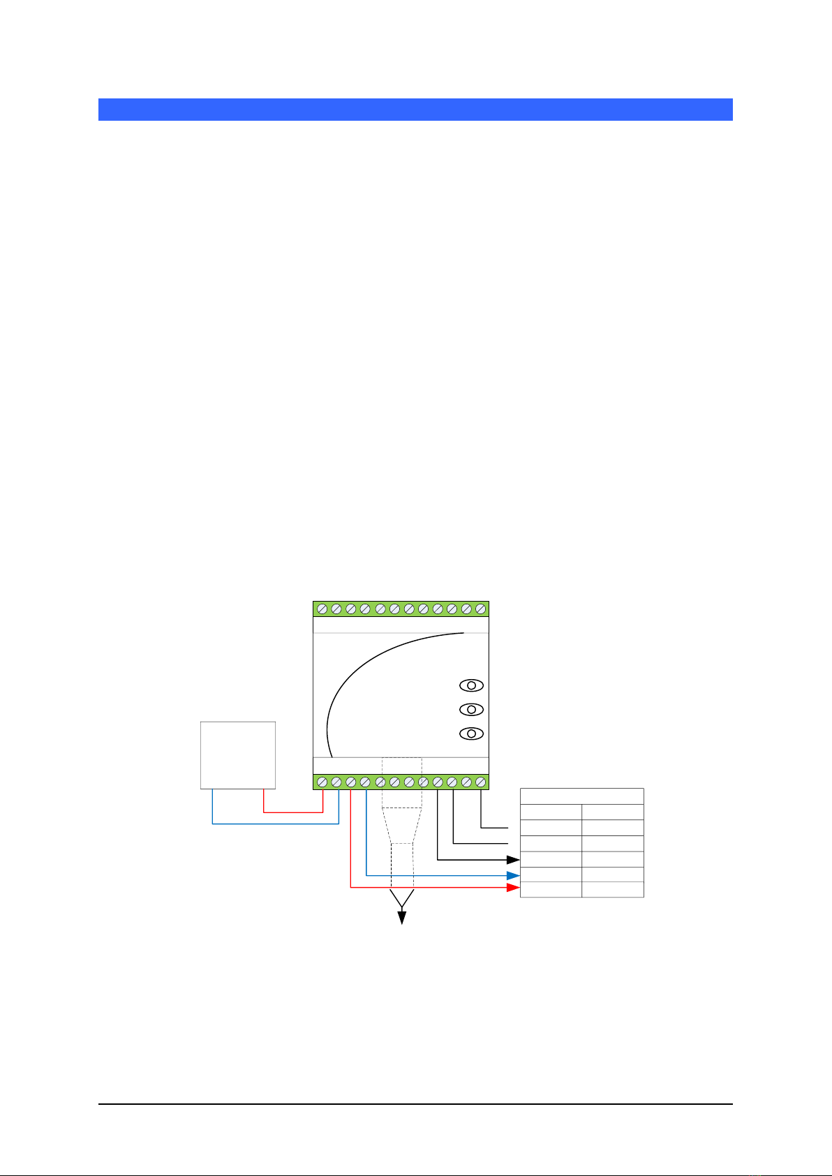
2.1.1 Location of the Ethernet Adapter (EA01)
The Ethernet Adapter should be mounted in the wiring junction box as close to the Hydro-
Control VI as possible, and protected from water and excessive dust. Connect the
Ethernet drop cable from the network connection to the Ethernet port of the Adapter.
Connect a 24V dc supply to the 24V+ and 0V input terminals of the Ethernet Adapter,
ensuring that the power supply and wire is of a sufficient power rating to carry the power
for the number of sensors connected.
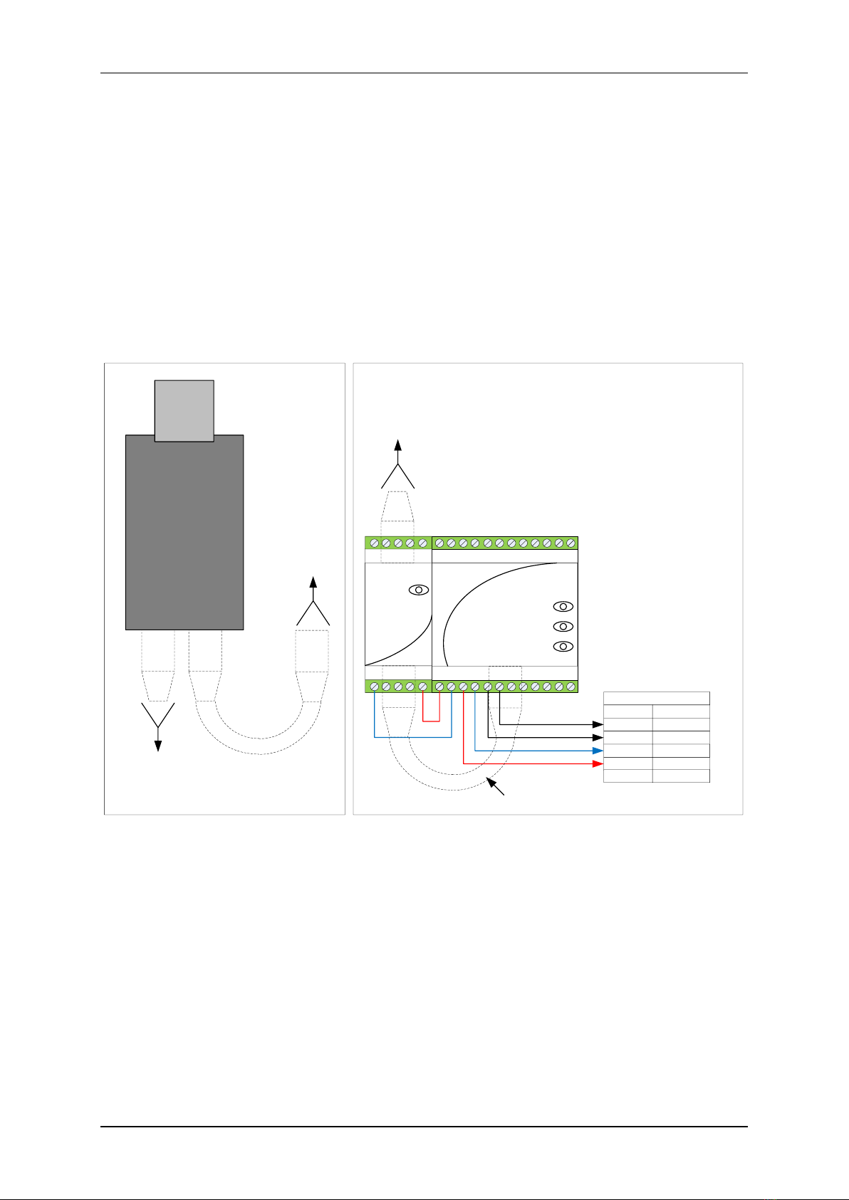
2.2 Power over Ethernet (EPK01)
A single Hydro-Control VI unit (with attached Hydro-Mix sensor) can be powered using the
Power over Ethernet kit. Connect one of the Sensor 24V and 0V connections to the Hydro-
Control VI power input pins. The arrangement is as shown below:
10/100baseT
CAT5e
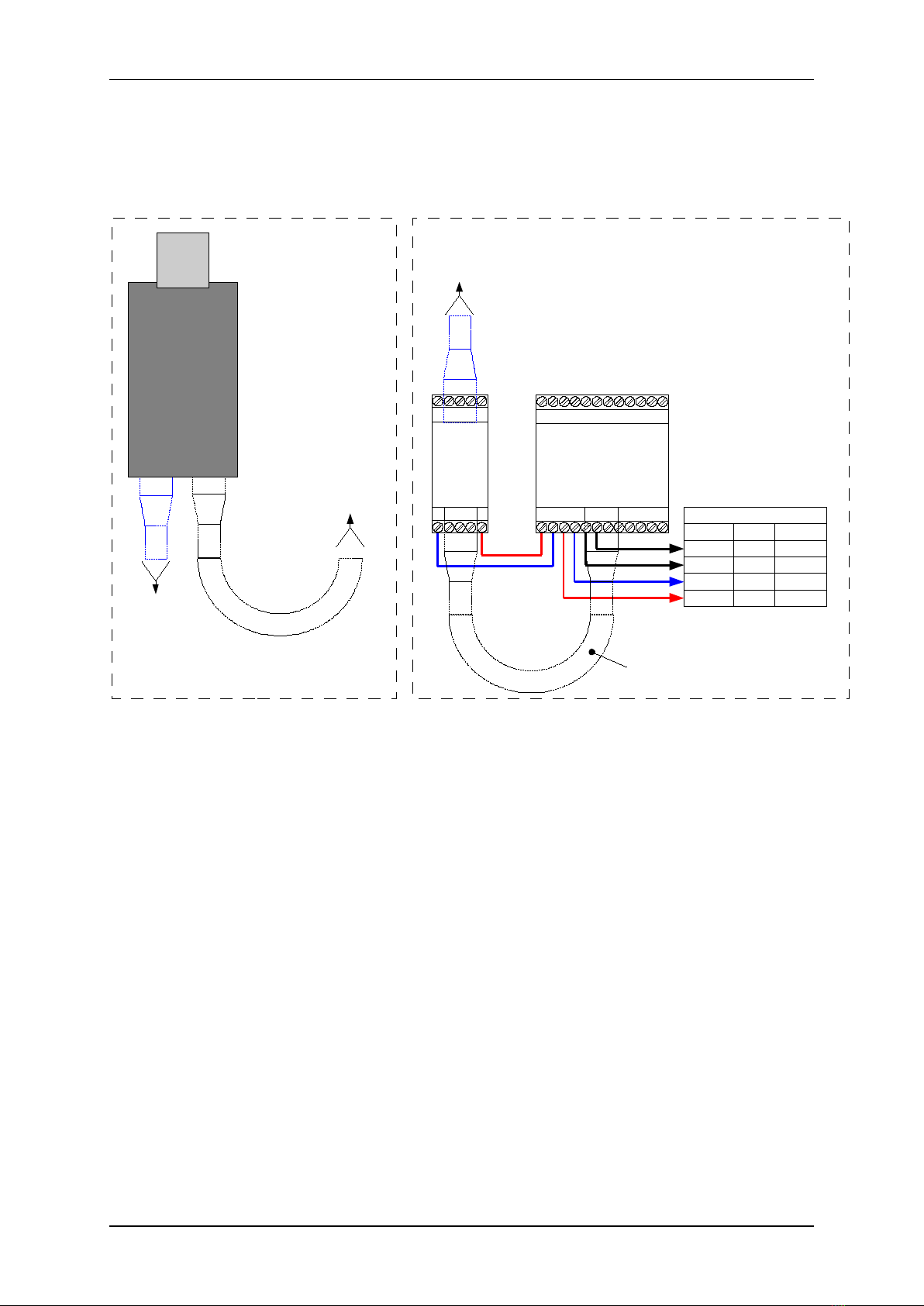
Linking EPA01 and EA01
Connections to Hydro-Control VI
Description Connector Pin
RS232 Gnd 28
RS232 Rx 26
RS232 Tx 27
0v DC 34
Ethernet
Adapter
Model: EA01
24V
Receive
Transmit
Ethernet
Power
Adapter
Model: EPA01
IN
24V
OUT
Junction box close to Hydro-Control VI
Control Room Cabinet
10/100baseT
CAT5e
Ethernet
to EPI01
10/100baseT
CAT5e
Ethernet
to Network
Switch
EPI01
Ethernet
Power
Injector
OUT IN
10/100baseT
CAT5e
Ethernet
to EPA01
IEC Mains
Cable
100-240v AC
50-60Hz
24v DC 32
Figure 6: Connecting the Ethernet Adapter to Hydro-Control VI
with Power Over Ethernet Option
2.2.1 Location of the Power Adapter (EPA01)
The Power Adapter Module (EPA01) should be mounted in the wiring junction box with the
Hydro-Control and beside the Ethernet Adapter, protected from water and excessive dust.
Connect the Ethernet drop cable from the router to the IN port of the Power Adapter. This
cable carries both the power and the Ethernet communications signals. Connect a short
Ethernet cable from the OUT port of the Power Adapter to the Ethernet port on the
Adapter. This cable carries only the Ethernet communications. Connect short insulated
wires from the 24V+ and 0V outputs of the Power Adapter to the 24V+ and 0V inputs of
the Ethernet Adapter, ensuring that the wire is of sufficient power rating to carry the power
for the Hydro-Control VI and it’s sensor.
Connect RS232 cables between the Ethernet Adapter and the Hydro-Control VI.