Hyundai HYUNDAI AUXILIARY JACK/FM MODULATO User manual

INSTALLATION INSTRUCTIONS
HYUNDAI AUXILIARY JACK/FM MODULATOR
2007 HYUNDAI VERACRUZ
PART NUMBER: U8550-00100
4fo1egaP70//054
Recommended Tools:
Phillips Screw Driver Drill
3/4’’ Drill Bit 3/32’’ Drill Bit
Plastic Trim Panel Removal Tool Pliers
10mm Socket & Ratchet
Read and understand these instructions BEFORE attempting to install this product.
2007 Hyundai Veracruz
Parts Included in kit:
FM Modulator
Jack Connector
Switch Plate
Wire Ties/ Felt/ Phillips
Head Screws/ Scotch Lock
24’’ Long 3.5mm to
3.5mm Audio Cable
Felt
LINE-IN
L
R
FREQUENCY SELECT
POWER
CAR ANT
AUDIO ANT
2 A
.
.
.
.
.
.
.
Noise can be introduced into the system if the source audio device is playing while
simultaneously being charged through the vehicle’s 12V DC power outlet. If this noise is
excessive, please disconnect the DC charger.
For optimum sound quality, it is recommended to set the source audio device volume to
75% maximum output level, then use the head unit to adjust the volume.
SPECIAL OPERATION NOTES
Pocket Divider
Audio Input

4of2egaP
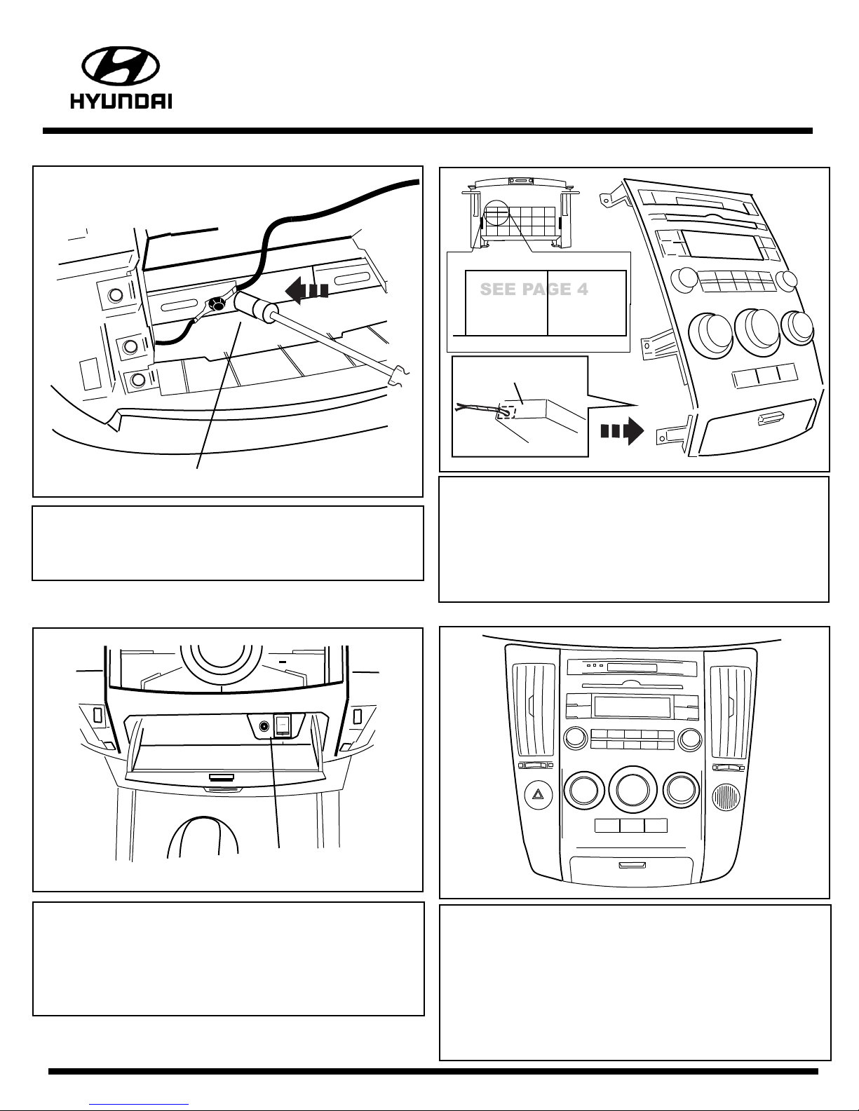
a. Unsnap vent panels on either side of radio using plastic
trim removal tool.
b. Remove (10) phillips screws from radio/AC panel.
c. Pull radio/AC assembly out, unplug harness connectors
and remove.
STEP 1 Radio Removal CAUTION: Use plastic trim removal tool to prevent damage or scratches to vent panels.
..........
..........
..........
..........
..........
..........
d. You should have a clear view of the dash cavity.
STEP 2 Installing the FM Modulator
a. Attach FM modulator to bottom of lower plastic
cross brace using two 11’’ wire ties.
b. Plug male car antenna lead into female antenna
lead on FM modulator and wrap connection with felt.
c. Use 3M Scotch Lock to splice Red wire into the factory
radio harness Green with Black stripe wire.
NOTE: Be sure to test with a Multi-Meter
to verify.
Hyundai Factory Radio Harness Connector
3M Scotch
Lock
FM Modulator
+12v Red Power Wire
Green/ Black
Stripe
70//054
4fo3egaP
STEP 2 Installing the FM Modulator (Contd.)
d. Connect black wire to lower metal cross brace
(has existing factory ground wire in this location).
Loosen bolt and slide spade connector in and tighten bolt.
a. Remove storage bin by removing (4) mounting screws.
b. Drill 3/4’’ hole in the back left side of storage bin below
AC controls, as viewed from back of the unit.(Fig.1)
c. Route RCA and power plug through drilled hole.
d. Drill (2) 3/32’’ on the places marked (X) on the above
illustration.(Fig.4, See last page for template of proper
location on where to drill holes).
STEP 3 Installing the Jack Connector Switch Plate
STEP 3 Installing the Jack Connector Switch Plate (Contd.)
e. Make sure you plug in both RCA and power plugs to FM
Modulator and wrap with felt.
f. Carefully secure modulator harnesses to prevent rattles
using the 8’’ wire ties.
g. Once all connections have been made place the pocket
divider over the outside wall of the switch plate.(Fig.2)
a. Reconnect radio and AC controller wire harness
connectors.
b. Secure radio/ AC assembly with the (10) screws previously
removed.
c. To eliminate potential rattles be sure to check proper
installation of the white retainer clips.Snap side panels
back in place.
d. The installation is now complete.
e. Place User Instruction Sheet and 24’’ Audio Cable into
glovebox.
STEP 4 Re-Installing the Radio/ Vent Panels
10mm Socket
Connector
Switch Plate
Back view of storage bin
70//054
............................................x
x
Drill Drill
Fig.1
Fig.4
SEE PAGE 4
xx
............................................
Drill Drill
Actual Size

Step 1. Place bin illustration template over the actual bin of the vehicle. (See Fig.4)
Be sure to align the boxed diagram directly onto the bin.
Hint: Feel around on the boxed area on the bin illustration to check if the template is aligned to the bin as best
as possible.
Step 2. Cut out the dotted lines on the illustration so that the brackets fit through to align the bin template.
Step 3. Using a drill, drill (2) 3/32’’ holes where the template is marked with an “X”.
Note: Be sure to drill all the way through the top wall of the bin.
Step 4. Place Jack Connector Switch Plate against the right hand side wall and behind the felt line. (See Fig.3)
Step 5. Using a drill, screw in the supplied screws through the bin and switch plate, be sure to hold pressure on the switch plate.
Step 6. Apply tune label to the inside of the bin door. (See note in Fig.3)
4fo4egaP
70//054
FIG. 4
xx
Drill Drill
Actual Size
TOP VIEW OF BIN
FIG. 3
FRONT
REAR
Template Instructions (Step 3c)
Pocket Divider
Veracruz Storage Bin Drilling Template
Tune Label
Location
Tune Radio to 88.3MHz
FIG. 2
This manual suits for next models
1


