I-Gard DSP-OHMNI User manual
Instruction Manual C-429EM,
DSP-OHMNI Version 2, June 2010
dsp ohmni
the power to protect
HIgH RESISTANCE
gROUNDINg SYSTEM
DSP-OHMNI
VERSION 2
Cross Reference RA Part Number PN-252626

IMPORTANT
Each DSP module is carefully inspected before packed in a specially designed carton.
The unit should be examined immediately upon receipt. If damage or indication
of rough handling is apparent, a claim should be filed without delay with the transport company.
I-Gard should be notified promptly if replacements for damaged goods are necessary.
If units received are not to be installed immediately they should be stored in their original
containers in an area free of dust and moisture.
The DP-OHMNI Version 2 offers added features and versatility than previous versions.
It is important to note that Version 2 modules are NOT compatible with Version 1 modules
and vice versa. All Version 2 modules are labeled and identified by indicating either V2 or Version 2.

DSP-OHMNI Instruction Manual 429EM Version 2, June 2010 I-GARD
3
1INTROduCTION
High-Resistance-Grounding is becoming more prevalent in industrial and commercial electrical power
systems. As the need for reliable and stable power increases the inconvenience of unwanted downtime
in processing, robotics and data service also become more critical and costly.
Single Ground Faults in motors and equipment are common and will cause interruption of service in Solidly
Grounded systems. HRG prevents this event from happening by limiting the fault current to a sustainable
level for an indefinite time.
The DSP-OHMNI system will provide the user with an Alarm and indication of the location of the fault using
a combination of voltage and current measurements.
In some applications, however, it is desirable to clear any fault on the system when it occurs with fire
prevention or protection of sensitive equipment being the main concern rather than continuity of service.
e.g. petro-chemical, grain handling. In this case, in addition to fault indication the DSP-OHMNI can be
programmed up to Trip the breakers associated with the fault with or without adjustable Time Delay.
The DSP-OHMNI system is designed to detect the event of a single fault and signal an alarm condition and
point to the affected branch or feeder. Thus maintenance can be immediately alerted to the problem and an
operator dispatched to locate the fault to isolate it promptly. The DSP-OHMNI system can assist in locating
the fault with a pulsing fault location circuit that modulates the current in the fault circuit. This allows the
operator to identify and locate the fault location though the branch circuit which is carrying fault current by
using a portable clamp-on current probe connected
to an ordinary ammeter (DMM) meter.
Additionally, the DSP-OHMNI has two TRIP modes of operation. It can be set up to control circuit breakers
to TRIP on the occurrence of a single fault with or without time delay, or if the Feeder Circuit Ground Fault
current exceeds 100A on two (Phase to ground to Phase) faults. (This can only occur when two faults exist
since the current on a single fault cannot exceed the Grounding Resistor Rate current) the DSP-OHMNI can
then be set up to selective second ground fault trip on a priority basis to protect the critical feeder. Because
two circuits will be involved it is possible to prioritize which circuit will be interrupted by an priority setting.
This ensures that only the least important circuit is interrupted.
Where it is important to protect sensitive equipment, the DSP-OHMNI can be setup to TRIP the faulted
Feeder Module on the first fault, with, or without, time delay (up to 99 minutes). The Alarm Level is normally
set at 50% (default) of the system maximum ground current, however with the DSP-OHMNI Version 2
system other Alarm Levels between 10% and 90% may be set as desired.
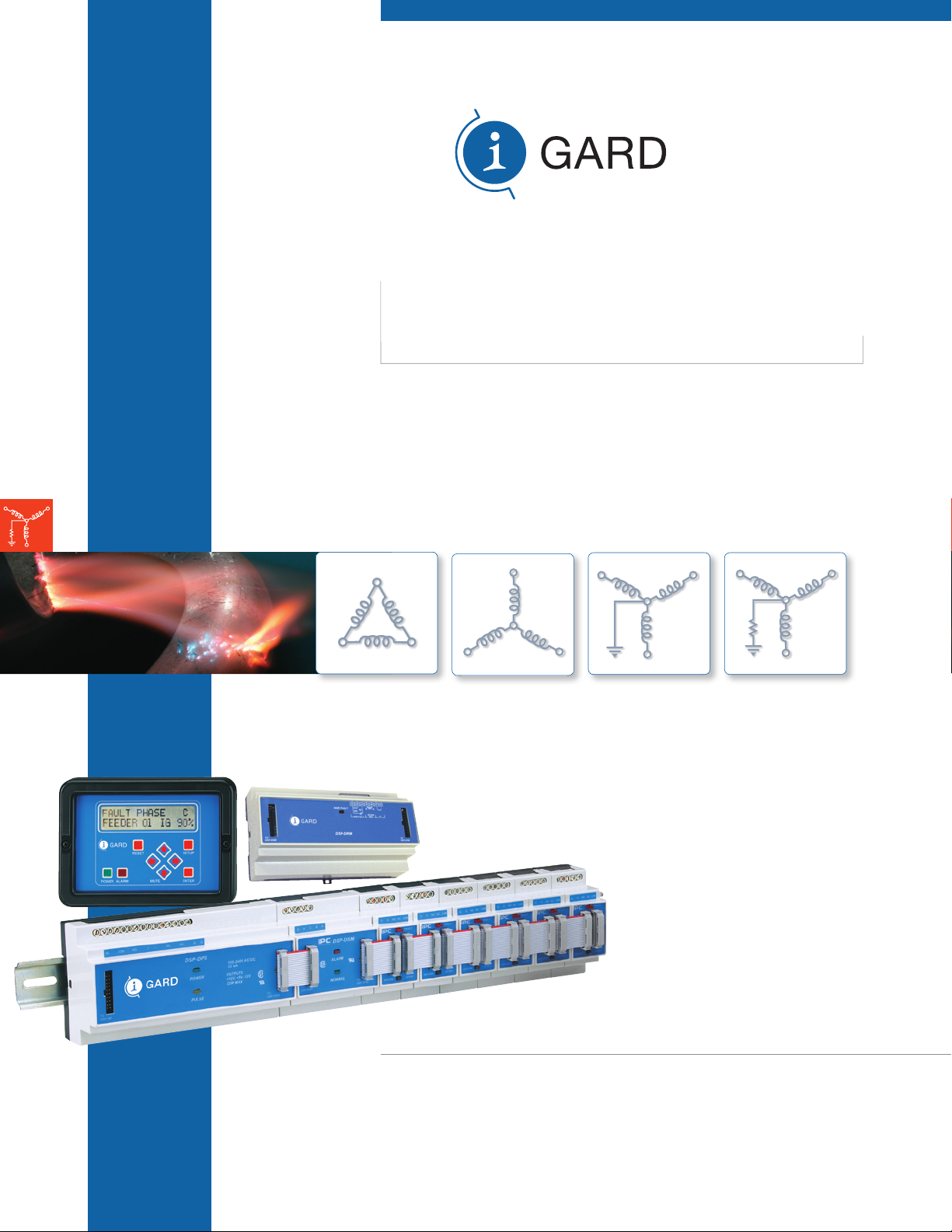
The DSP-OHMNI system consists of a number of modules that are mounted on a 35mm DIN rail
typically located in a control compartment of switchgear. The modules are connected together through
20-conductor standard ribbon cable. A panel-mounted Display module provides a human interface to the
system allows set-up and control.
There are four DSP modules as follows: Additionally there are other optional modules
DSP-DM Display Module DSP-DRM Grounding Resistor Monitor
DSP-DPS Power Supply DSP-DLM Data Logging Module
DSP-DSM System Module DSP-CA Cable Adapter
DSP-DFM Feeder Module DSP-CAS Cable Adapter with on/off switch

I-GARD DSP-OHMNI Instruction Manual 429EM Version 2, June 2010
4
The Display Module is a panel-mounted enclosure designed for flush mounting in a door. It is connected by
a ribbon cable to the Power Supply unit. The DSP-DM display indicates faulted phase, total system leakage
current, feeder branch current level and provides other information such as priority settings and Resistor
setting etc. It is used to set-up the system and provide manual control of the pulse location system. The
DSP-DM also provides MODBUS RTU communications through a RS-485 network to external information
systems.
The POWER Supply unit DSP-DPS is a DIN rail-mounted modular unit constructed with an ABS enclosure
and provides +5V, +12V and -12V regulated power to all of the modules through the front ribbon cables. It
is capable of operation with a wide range of input voltage supplies from 100V to 240V ac without selection
of any jumpers or switches. It can also operate when supplied with DC voltage from 125V to 250V DC. The
Alarm Relay contacts are also located on this unit.
The System Module monitors the system line-to-ground voltages through a standard I-Gard Corp. DDR2
voltage sensor unit. It determines if there is voltage unbalance in the system and the level
of ground fault current in the grounding resistor by measuring the voltage displacement of the neutral from
ground, without any connection to the Neutral Grounding Resistor. It also signals phase indication to the
DSP-DM Display.
The Feeder Modules (DSP-DFM) measure the fault current level in the branch circuits that are protected.
This module uses standard I-Gard zero sequence current sensors Type TxA or Rx-yA. It is equipped with
a form C 10A output Relay that can be used for breaker control. The DSP-DFM detects two fault levels.
Firstly it detects the single fault, which creates a System Alarm condition, and secondly through a priority
level system it provides breaker control to disconnect the least important circuit breaker in the event of a
second fault occurrence providing continuity of supply to the critical feeder. Through the setup of the DSP-
DM Display, DSP-DFM is automatically set to the same Alarm level as that of the System Module during
Feeder Module Setup.
Note: If the Alarm level is changed in the System Module (or the System Module has been changed) then it
may be necessary to Setup the DSP-FM modules afterwards.
The DSP-DRM module is used to monitor the integrity of the neutral grounding resistor for change of
resistance and/or open circuit condition. It is installed in the same line-up of modules as the rest of the DSP-
OHMN system with ribbon cable jumpers. The DSP-DRM uses external I-Gard zero sequence current sensors
and a NGRS Resistor sensor which provide voltage and current at the Neutral Grounding grounding resistor.
The DSP-DRM uses the same Alarm system as the rest of the DSP-OHMNI system. See Section 12 for
detailed information.
In order to capture event information, a data logging module type DSP-DLM has been designed to enhance
the standard last-fault event indication. This module may be inserted anywhere in the DFM line-up with
ribbon cable connections. The module includes a real-time clock to signal the event time and date of each
event captured. Events captured are Loss of DDR-2 phase(s), Bus Fault, Feeder Fault, Feeder Trip and NGR
fault for both Trip-on-First-Fault, and Trip-on-second- fault setups. The DSP-DLM date stamps the events
according to the time and date set up on the DSP-DM during the system set-up.
The Cable Adapter Modules DSP-CA and DSP-CAS are used when two or more DSP-OHMNI systems are to
prioritize in main-tie-main systems for example. These modules convert the ribbon cable conductors involved
to shielded cable for connection to the other DSP-OHMNI systems. The DSP-CAS is equipped with solid
state switches to allow connection only when the input terminals of this unit are shorted (normally by a tie
breaker contact for example).
I-GARD DSP-OHMNI Instruction Manual 429EM Version 2, June 2010
6
The DDR2 provides output voltages VAG, VBG, VCG that are proportional to the phase to ground voltage and also
voltage VNG that is proportional to the neutral resistor voltage. ( i.e. Total leakage/fault current of the system)
On large systems provision is usually made to ground the system using a current-limiting resistance
(I-Gard Type OHMNI-PM). On ungrounded systems there is always leakage capacitance to ground from
each line. Re-striking ground faults may cause an excessive build up of line to ground voltage due to
this capacitance. It may be stabilized with the addition of a grounding resistance, thus preventing costly
breakdown of insulation.
The OHMNI-PM is connected between ground and the Neutral (star) point of the transformer on Wye
systems. On Delta systems an artificial neutral device (I-Gard Type DDAI) is required to provide a Neutral
(star point). Both OHMNI-PM and DDAI devices are selected for appropriate current ‘let-through’, i.e.: The
current, which will flow to ground, if there is a direct short from line to ground (on any one phase).
NOTE: A good Rule-of-Thumb for Resistor current selection is 1 ampere per 2000KVA, if no surge capacitors are on the system,
and 1 ampere per 1000KVA with surge capacitors.
DDAI and OHMNI-PM devices are available with UL Listing for continuous currents of 1 ampere to 10
amperes and up to 600 Volts for most systems. Other Voltages and ratings are available upon request. For
further information regarding the use of these devices refer to:
Instruction Manual Type DDAI Artificial Neutrals C-430EM
Instruction Manual Type DDR2 Alarm Resistor Units C-440EM
Instruction Manual Type OHMNI-PM Neutral Grounding Resistors C-450EM
Instruction Manual type CA(S) Modules C-415EM
3INSTALLATION
A typical installation will include for each power source (transformer/generator) 1 DSP-DM, 1 DSP-DPS, 1
DSP-DSM, 1 DSP-DRM, 1 DSP-DLM and a number of DSP-DFM Feeder Modules as required with 1 for
each branch protected. Additionally there will be a DSP-OHMNI-PM pulsing resistor to ground the system.
A voltage-sensing resistor DDR2 is required for the DSP-DSM input, as well as one current sensor for each
DSP-DFM for current detection. See Table 3.1 for typical requirements.
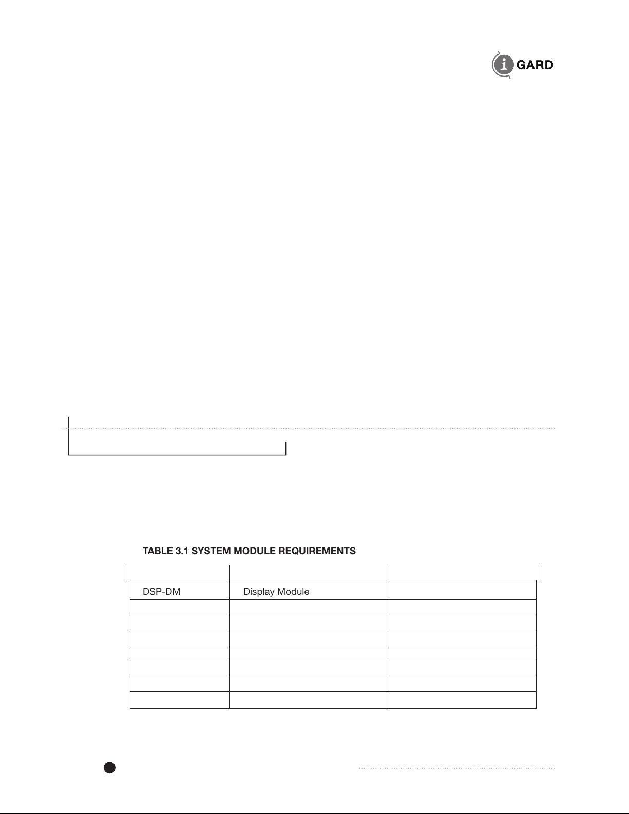
TABLE 3.1 SYSTEM MODULE REQUIREMENTS
Catalog Number Description No Required/System
DSP-DM Display Module 1
DSP-DPS Power Supply 1
DSP-DSM System Voltage Module 1
DSP-DFM Feeder Module As required 1/ Circuit
OHMNI-PM Pulse Equipped Resistor 1
DDR2 Voltage Sensing Resistor 1
DDAI Artificial Neutral Required only for delta system
TxA or Rx-yA Toroidal Current Sensor 1/Feeder Module

I-GARD DSP-OHMNI Instruction Manual 429EM Version 2, June 2010
36
16 SPECIFICATIONS
Power Requirements DSP-DPS 100-240V, 50/60Hz or DC, 25VA
Maximum Ratings DSP-DPS
Control voltage 250V AC/DC
Dielectric
Relay contacts to chassis 1500V rms. for 1 minute
Control terminals to chassis 1500V rms. for 1 minute
DC output maximum rating 22W max for +5, +12 and 12V supplies
Settings DSP-DSM System Module
Alarm Level Pickup 10% to 90% in 10% increments of system Ground Current IG
Pulse Set-up
Pulse Rates
0 to 9 Setting in 0.25Hz increments 1.0,1.25,1.50,1.75, 2.0, 2.25, 2.50, 2.75, 3.0, 3.25Hz.
Pulse Modes Normal, Inverted
Pulse Interlock Normal, Interlocked with Fault Detect.
Pulse Output current 0.5A @ 12V DC
DSP-DFM
Ground Current Settings IG 1,2,3,4,5,6,7,8,9,10,11,12,13,14,15,16A
Trip Level Current 100A
Trip Level Delay 10xP +200mS (Where P=Priority setting)
Priority Levels 0 – 15 (16 settings)
Contact Ratings
DSP-DFM Trip Contacts Form C SPDT 10 amperes, 240V AC resistive
8A 24V DC
DSP-DPS Alarm Contacts Form C SPDT 8 amperes, 240V AC resistive
8A 24V DC
DSP-DPS Pulse output DC Source 100 milliamperes, 12V dc maximum
Performance
DSP-DFM
Maximum No. of Modules 50
Pickup accuracy ±10% of system let-through current
Trip Level accuracy ±10A
Trip Delay Trip on 2nd Fault
Digital Trip delay 200mS+(10 x priority*) mS (e.g. if priority is 5 then 200 +5x10=250mS)
*the priority factor only applies if the two faults occur at the same instant otherwise the delay will be simply 200mS
Analog Backup delay 1 Sec.
Trip Delay on 1st Fault
Minimum Setting (00 position) Fixed 0.1 Sec.
Adjustable 01 to 99 minutes
DSP-DSM
Alarm Level Accuracy ±10% of IG
Meter accuracy ±10% of IG
Note: Accuracy based on single resistance fault, at nominal line voltage, without system capacitance.
Other manuals for DSP-OHMNI
1
Table of contents
Popular Industrial Electrical manuals by other brands


Murata
Murata GRM153R60G475ME15 Series Reference sheet

Murata
Murata GRM21BR72A103JA01 Series Reference sheet

Murata
Murata GRM0335C1H1R2BA01 Series Reference sheet

Murata
Murata GRM0335C1H3R1CA01 Series Reference sheet

Murata
Murata GRM1885C1H471JA01 Series Reference sheet

Murata
Murata GRM0335C1HR30WD01 Series Reference sheet

Siemens
Siemens 3WX31 46-7C1 3 Series operating instructions

Murata
Murata GRJ188R72A104KE11 Series Reference sheet

Murata
Murata GRM155C81A225ME44 Series Reference sheet

Murata
Murata GQM1555C2DR70WB01 Series Reference sheet

Murata
Murata GRM1885C1H181JA01 Series Reference sheet

Murata
Murata GJM0335C1H3R0BB01 Series Reference sheet