Autolab/Electronic load combination
4 | Page
1 – Choice of the electronic load....................................................................... 5
2 – Dynload interface part list ........................................................................... 6
3 – Autolab part list .......................................................................................... 8
4 – Electronic load part list ................................................................................ 9
5 – Polarity convention.................................................................................... 10
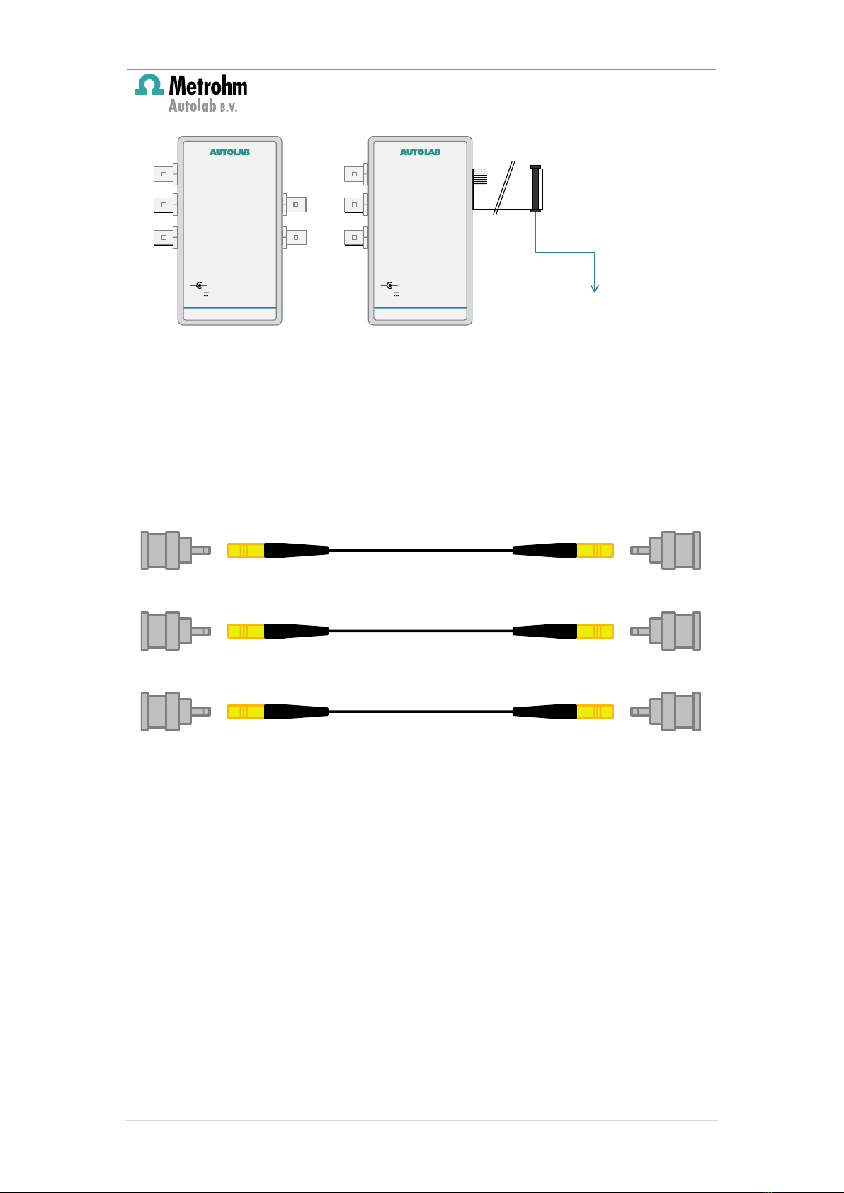
6 – Connections to the Dynload interface ....................................................... 10
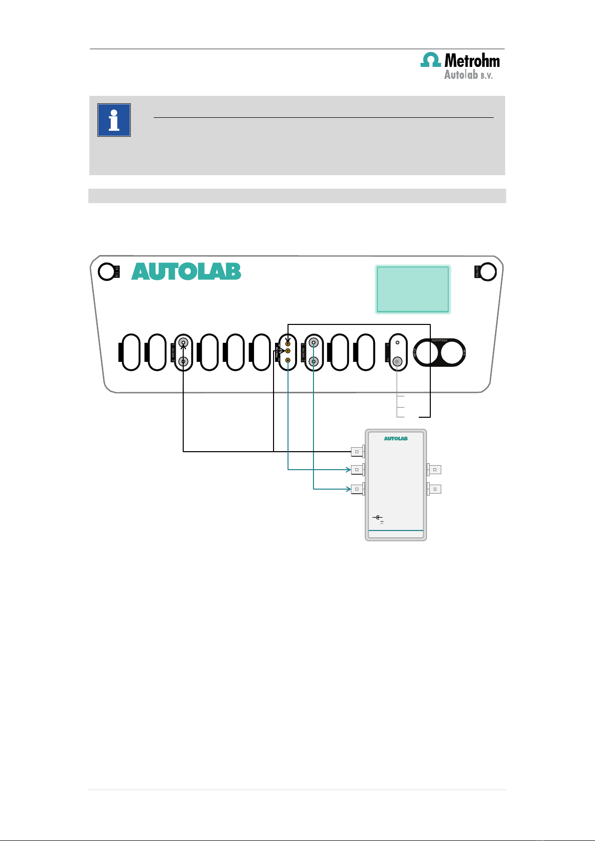
6.1 – Connections without a FRA module .................................................. 10
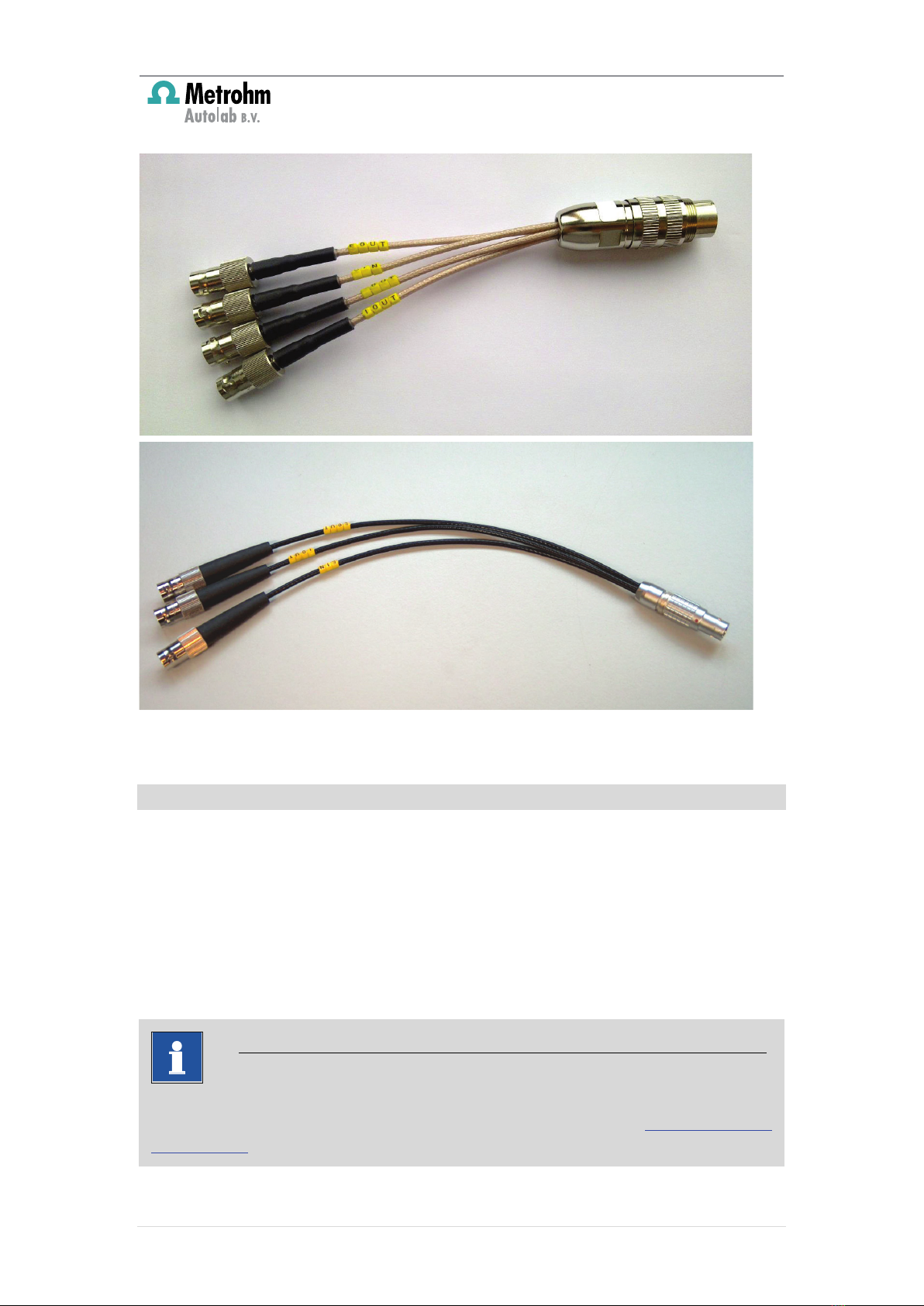
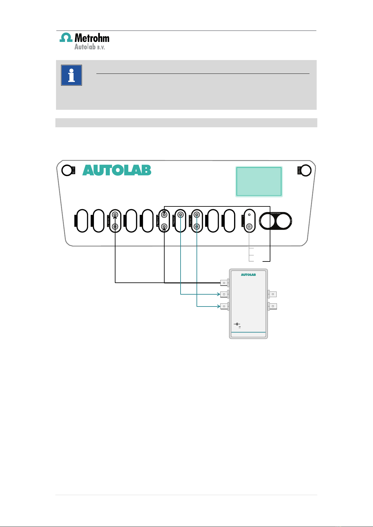
6.2 – Connections with a FRA32M module ................................................ 12
6.3 – Connections with a FRA2 module...................................................... 13
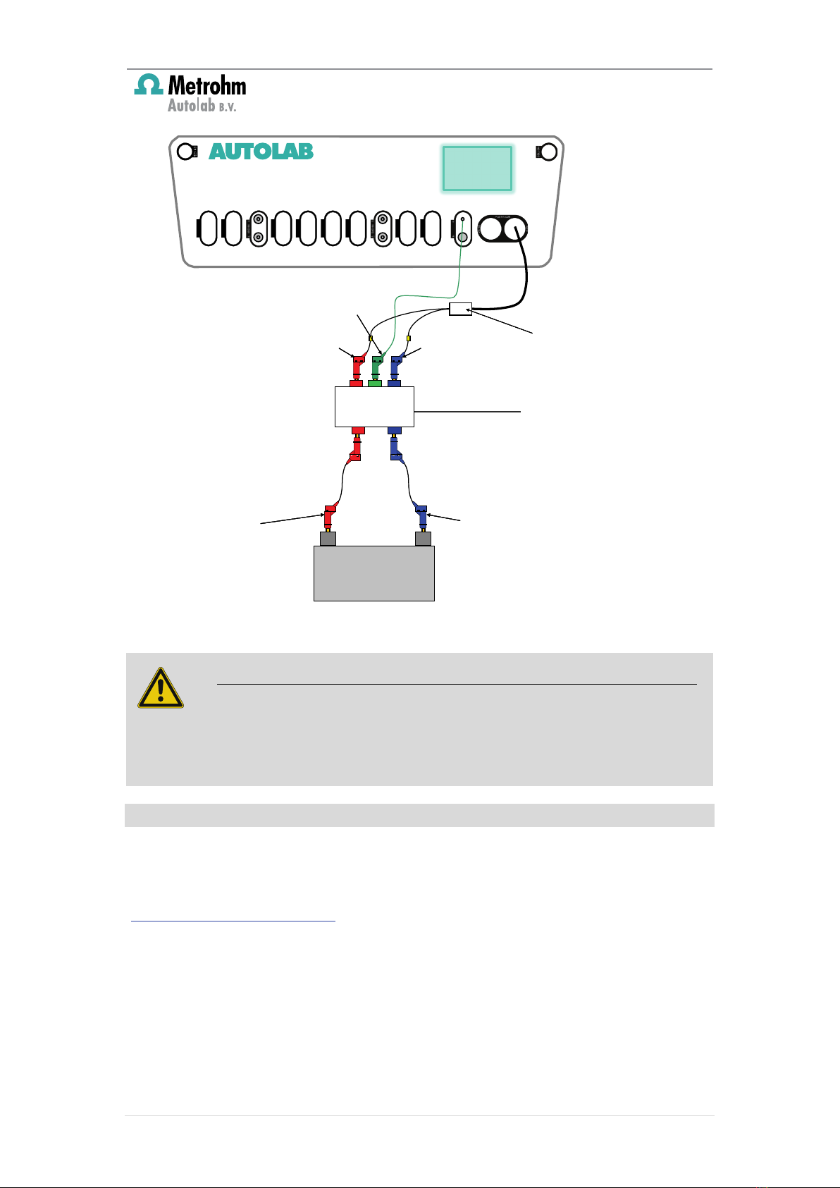
7 – Connections to the cell.............................................................................. 14
7.1 – Connections for cell voltages ≤ 10 V ................................................. 14
7.2 – Connections for cell voltages > 10 V ................................................. 15
7.2.1 – Voltage multiplier part list.......................................................... 15
7.2.2 – Connections to the instrument................................................... 16
8 – Electronic load settings.............................................................................. 17
8.1 – Programming the load (TDI) .............................................................. 18
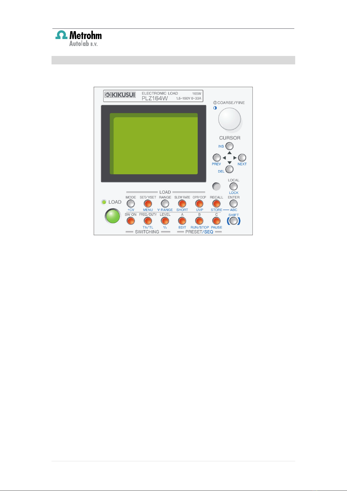
8.2 – Programming the load (Kikusui) ........................................................ 19
8.3 – Controlling the electronic load .......................................................... 20
8.3.1 – Controlling the electronic load (TDI)........................................... 20
8.3.2 – Controlling the electronic load (Kikusui)..................................... 20
9 – NOVA hardware setup .............................................................................. 21
9.1 – Analog input settings ........................................................................ 22
9.2 – Analog output settings...................................................................... 23
10 – Manual control of the electronic load (DC only)....................................... 24
11 – Procedure control of the electronic load (DC only)................................... 27
12 – Recording the output from the electronic load (DC only)......................... 30
13 – Impedance spectroscopy measurements ................................................. 33
13.1 – External settings.............................................................................. 35
13.1.1 – Settings for V ...................................................................... 35
13.1.2 – Settings for X ...................................................................... 36
13.1.3 – Settings for Y ...................................................................... 36
13.1.4 – Settings for Transfer function................................................... 37
13.2 – Frequency scan settings .................................................................. 38
13.3 – Sampler settings.............................................................................. 39
13.4 – Plots settings................................................................................... 41
13.5 – Running a measurement ................................................................. 42
14 – Measurement examples .......................................................................... 44
14.1 – iV/Power curve................................................................................ 44
14.1.1 – Running the measurement....................................................... 44
14.2 – Impedance spectroscopy measurement........................................... 45
Appendix 1 – Specifications of known electronic loads ................................... 48
Appendix 2 – Modification of the FRA2 module.............................................. 49