iBeLink DM22G Blade Operating instructions

Troubleshooting the iBeLink DM22G Blade
11/18/2017 Rev1.1 Fixed steps for Section I.
This guide will help you to troubleshoot and fix some common issues that can occur on the
iBeLink DM22G Blades. The three most common issues that can occur are the following: Blade
not being detected, not detecting all chips on a Blade, and displaying a high H/W reading.
I. Blade not Detected
The first thing to check is for a conductivity issue.
1. Remove the black and steel metal bar that is across the top of the blades. They are
held in place by 6 screws. See picture below.
2. Remove the 4 screws attaching the Blade to the case.

3. Slightly lift the blade up away from the case.
4. If the Blade is now detected, the issue is caused by conductivity and can be fixed by
following the Fixing Blade Conductivity Issue section further below. If the Blade is
still not detected, it could still be a conductivity issue so follow the Fixing Blade
Conductivity Issue guide and test again.
5. After following the Fixing Blade Conductivity guide, check if Blade is detected
without installing the black and steel bars. Then install the metal bars and check
again to make sure the fix is complete.
II. Not Detecting All Chips
Check to see if the issue is from the panel board, hashing board, or both.
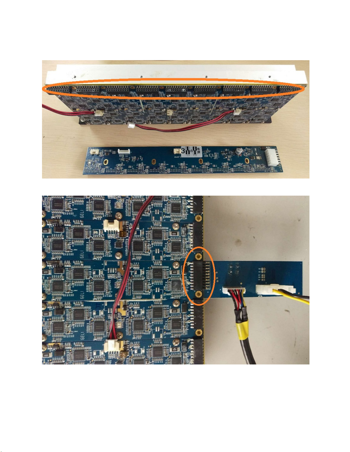
1. Check the panel board: Check the transistors located near the edge of the panel
board to see if any have been knocked off. A few have been circled in the picture
below. If some of the transistors are missing and the number of detected chips is a
multiple of 6, most likely it is only the panel board that is defective. Otherwise,
continue to the next step to check the hashing board.

2. Check the hashing boards: Check the status of the hashing boards by following the
iBeLink DM22G Hashing Board Test Guide section located further below.
3. Depending on your test results, you will need to request a RMA for the panel board,
hashing board(s), or both through the ticket system.
III. Displaying a High (15%+) H/W Reading
1. Reboot the miner. It may be necessary to reboot up to 3 times.
2. If after rebooting 3 times and the H/W reading is still high, let the miner continue to
run and check back in 12-24hrs.
3. After 12-24hrs have passed, check the H/W reading. If the reading has lowered,
there is no issue with the Blade. Otherwise, continue to the next step.
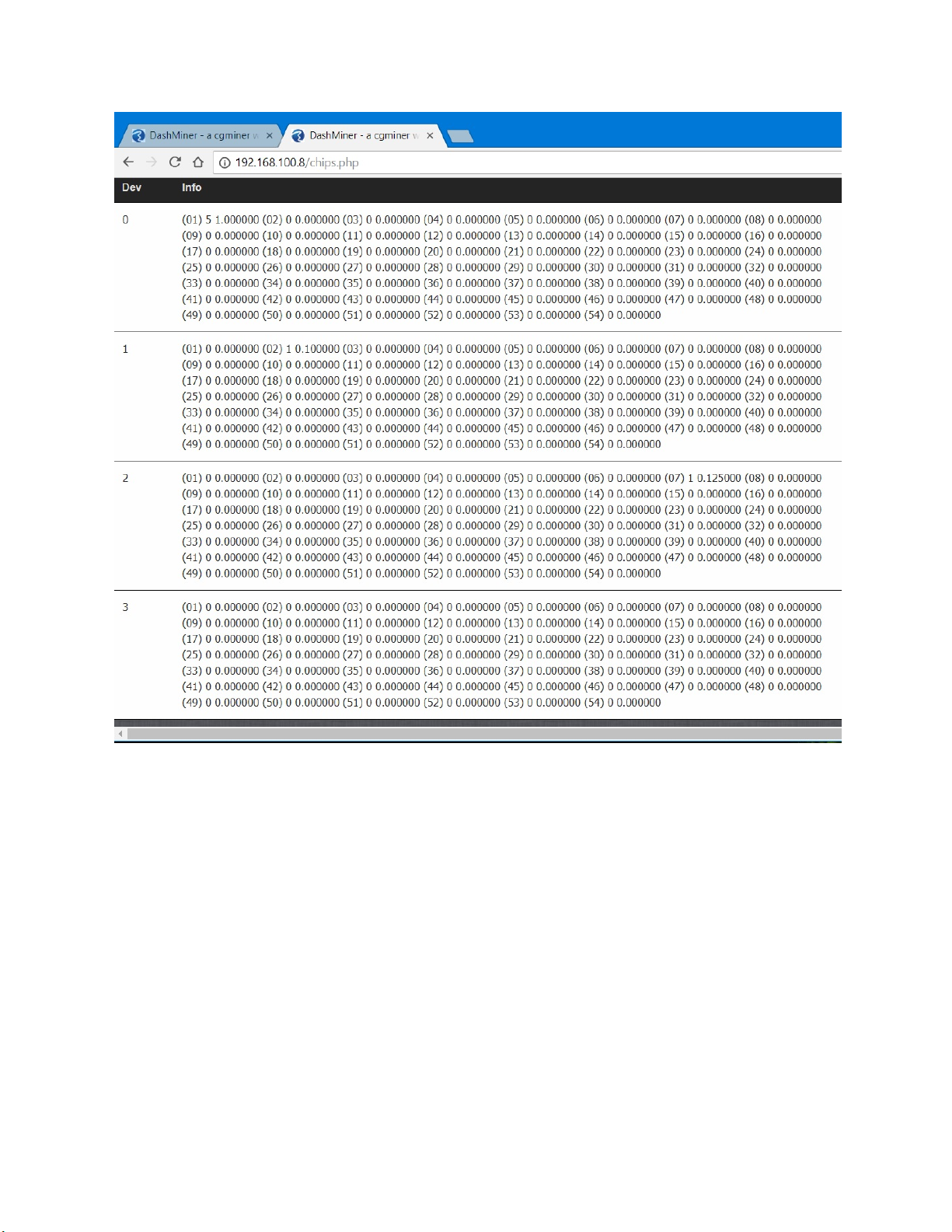
4. Find the chip reporting high H/W by going to “<miner hostname or IP
address>/chips.php” page. See picture below. The number in parenthesis indicates
the chip number. The next number is the amount of H/W errors followed by
percentage of the error. For example, you see (02) 1 0.100000. That means chip 2
had 1 H/W error, contributing 10% of the error.
5. Find the hashing board(s) that contains the chip(s) you found in Step 4. Each
hashing board contains 6 chips, and the hashing board order starts from the left side
of the Blade. See picture below. For example, chips 8, 9 and 22 are reporting high
H/W. Chips 8 and 9 are both located on hashing board #2 while chip 22 is located on
hashing board #4.
If the high H/W reading is caused by many chips each reporting less than 15%, try to
find the hashing board that has the most chips reporting the error.

6. Remove the hashing board(s) and note its number. You will need to request a RMA
for the bad hashing board(s) through the ticket system.
IV. iBeLink DM22G Hashing Board Test Guide
There are 2 methods to test the DM22G hashing boards: testing in a browser
environment and testing in a command line terminal. Testing in the browser
environment is recommended for the average user while testing in a command line
terminal is for developers. Both testing methods are shown below.
A. Setting up for Testing
1. You will need to have the test board as shown below, and the DM22G TestTool
Image.
Pic. 1: Test Board

2. Connect the hardware together.
a. First, connect the test board to the PI controller. Using the data cable,
connect one end to the connector port on the PI controller board labeled
NO.1 JP4. Connect the other end to the connector port on the back of the
test board labeled J1.
Pic. 2: Connector port NO.1 JP4 on PI Controller
Pic. 3: Connector port J1 on the back of the test board.
b. Connect power to the testing board with a 12V power cable from the psu.
c. Now connect the testing board to the hashing board. First, you will need to
remove the panel board to expose the connector ports on the hashing
boards. Then connect the pins X1 on the test board to the connector port X1
of the hashing board you are testing. Be sure the pins are connected
correctly and not reversed. (See Pic. 5)
Pic. 4: Panel board removed to expose hashing boards’ connectors
Pic. 5: Test board connected to hashing board.
B. Testing in the Browser Environment
1. Find the IP address of the test system. This can be done with the help of the
DHCP table in your router or using a program such as AdvancedIPScanner.

2. Enter the IP address you obtained in Step 1 into the URL address box. It is
recommended you use Firefox or Chrome.
Pic. 6: Web management page of the test system.
3. Click the “Single Test” to enter the test page.
Pic. 7: Test page
4. Click “Start Test” button and follow the prompt that appears. The “Key” is the S1
button on the test board. After pressing the button, close the message box. The
test will start running.

Pic. 8: The “Key” (S1 button) on the test board.
Pic. 9: Test is running.
In the event the “Key” is not pressed or there is something wrong with the setup,
you will get a prompt as shown in Pic. 10. To run the test again, just click “Start
Test”.
Pic. 10: Test has encountered an error.
5. After a moment, the test result will be shown. An “OK” will be displayed if the
hashing board has no problems and a “FALSE” if problems are detected.

Pic. 11: Hashing board has no issues.
Pic. 12: Problem detected on the hashing board.
6. At this point, you can run the test again on the same hashing board or connect
the test board into a different hashing board for testing.
C. Testing in a Command Line Terminal
1. Find the IP address of the test system. This can be done with the help of the
DHCP table in your router or using a program such as AdvancedIPScanner.
2. Access the miner using the IP address you obtained in Step 1.
3. Start the test program, serial_tester, located in /home/orangepi/share.
4. The test program will start and prompt with “wait TestKey press------“. The
“TestKey” is the S1 button on the test board. (See Pic. 8 above.) After pressing
the button, the test will continue.
5. After a moment, the test result will be shown. If a problem is detected on the
hashing board, the test will display an error message and exit the test program. If
no issues are detected, a successful message is displayed and will not exit the
test program. You can now connect the test board to a different hashing board
and continue testing. To stop the test at any time, press ctrl+c to exit the test
program.


