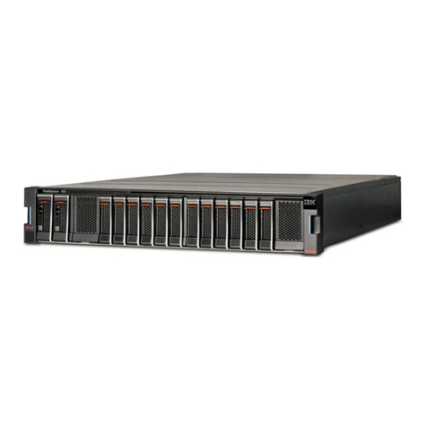
IBM Storwize V5100 MTM 2078-424 User manual

IBM Storwize V5100
Quick Installation Guide for MTM
2078-424, 2078-12F, 2078-24F,
2078-92F, and 2078-U5B
IBM

Note
Before using this information and the product it supports, read the following information:
• The general information in “Notices” on page 111
• The information in the “Safety and environmental notices” on page xiii
• The information in the IBM Environmental Notices and User Guide (provided on a DVD)
This edition applies to version 8, release 3, modication 0, and to all subsequent modications until otherwise indicated
in new editions.
© Copyright International Business Machines Corporation 2019.
US Government Users Restricted Rights – Use, duplication or disclosure restricted by GSA ADP Schedule Contract with
IBM Corp.

Contents
Figures.................................................................................................................. v
Tables.................................................................................................................. ix
Compliance standards.......................................................................................... xi
Safety and environmental notices....................................................................... xiii
Safety notices and labels.......................................................................................................................... xiii
Caution notices for the system............................................................................................................ xiv
Danger notices for the system ........................................................................................................... xvii
Special caution and safety notices..........................................................................................................xviii
General safety.................................................................................................................................... xviii
Handling static-sensitive devices........................................................................................................xix
Environmental notices...............................................................................................................................xix
About this guide..................................................................................................xxi
Who should use this guide........................................................................................................................ xxi
Publications and related libraries............................................................................................................. xxi
Related websites...................................................................................................................................... xxii
Sending your comments...........................................................................................................................xxii
Know how to report a problem.................................................................................................................xxii
Chapter 1. Before you begin the installation........................................................... 1
Reviewing your packing slip.........................................................................................................................3
Identifying the hardware components........................................................................................................5
Identifying Storwize V5100 node canisters.......................................................................................... 8
Verify environmental requirements.............................................................................................................9
Review enclosure location guidelines......................................................................................................... 9
Chapter 2. Installing the system hardware........................................................... 11
Installation overview................................................................................................................................. 11
Unpacking the Storwize V5100 control enclosure ...................................................................................12
Installing support rails for the control enclosures ...................................................................................13
Installing a Storwize V5100 control enclosure.........................................................................................14
Unpacking a 2U expansion enclosure ...................................................................................................... 16
Installing support rails for 2U expansion enclosures .............................................................................. 17
Installing an optional 2U SAS expansion enclosure ................................................................................ 20
Unpacking an optional 5U expansion enclosure ......................................................................................20
Installing an optional 5U SAS expansion enclosure.................................................................................23
Safety notices and considerations: 2077-92F, 2077-A9F .................................................................23
Weight considerations: 5U SAS expansion enclosure.........................................................................27
Identify the hardware components: 2077-92F, 2077-A9F ............................................................... 32
Unpacking and installing the enclosure: 2077-92F, 2077-A9F .........................................................35
Removing the top cover: 2077-92F, 2077-A9F ................................................................................. 38
Installing the support rails: 2077-92F, 2077-A9F .............................................................................39
Installing or replacing the fascia: 2077-92F, 2077-A9F ....................................................................43
Installing or replacing a drive: 2077-92F, 2077-A9F ........................................................................ 44
Installing or replacing the top cover: 2077-92F, 2077-A9F ..............................................................48
Installing an optional 5U SAS expansion enclosure........................................................................... 49
iii

Installing or replacing the cable-management arm: 2077-92F, 2077-A9F ......................................51
Removing and installing a SAS cable: 2077-92F, 2077-A9F .............................................................55
Connecting optional SAS expansion enclosures: 2078-92F, 2078-A9F ........................................... 57
Powering on the 2077-92F, 2077-A9F expansion enclosure.............................................................59
Powering off the expansion enclosure: 2077-92F, 2077-A9F .......................................................... 62
Storwize V5100 2078-92F, 2078-A9F expansion enclosure LEDs and indicators............................63
Storwize V5100 5U expansion enclosure parts ................................................................................. 68
Connecting the components .....................................................................................................................70
Connecting Ethernet cables to the node canisters............................................................................. 71
Connecting Fibre Channel cables to the control enclosure................................................................ 71
Connecting optional expansion enclosures to the control enclosure ................................................72
Powering on the optional 2U SAS expansion enclosures....................................................................75
Powering on the 2077-92F, 2077-A9F expansion enclosure.............................................................76
Powering on the system.......................................................................................................................79
Chapter 3. Conguring the system....................................................................... 81
Checking your web browser settings for the management GUI...............................................................81
Initializing the control enclosure...............................................................................................................83
Completing the initial system setup..........................................................................................................84
Verify and update the system rmware and software..............................................................................85
Chapter 4. Adding an expansion enclosure to an existing system.......................... 87
Chapter 5. Adding a control enclosure to an existing system ................................ 89
Appendix A. Accessibility features for the system.................................................91
Appendix B. Where to nd the Statement of Limited Warranty..............................93
Appendix C. Control enclosure requirements........................................................95
Appendix D. SAS expansion enclosure requirements.......................................... 101
Notices..............................................................................................................111
Trademarks..............................................................................................................................................112
Homologation statement.........................................................................................................................113
Electromagnetic compatibility notices................................................................................................... 113
Canada Notice.................................................................................................................................... 113
European Community and Morocco Notice.......................................................................................113
Germany Notice................................................................................................................................. 113
Japan Electronics and Information Technology Industries Association (JEITA) Notice.................114
Japan Voluntary Control Council for Interference (VCCI) Notice .................................................... 115
Korea Notice.......................................................................................................................................115
People's Republic of China Notice.....................................................................................................115
Russia Notice......................................................................................................................................115
Taiwan Notice.....................................................................................................................................115
United States Federal Communications Commission (FCC) Notice................................................. 116
Index................................................................................................................ 117
iv

Figures
1. Label showing the orientation of the node canisters and PSUs ..................................................................5
2. Orientation of ports on node canister 1 (top) .............................................................................................. 5
3. Orientation of ports on node canister 2 (bottom).........................................................................................6
4. Rear view of a 2077/2078-424 / 2077/2078-AF4 2077 expansion enclosure..........................................7
5. SAS ports and LEDs in rear view of an expansion canister for 2077/2078-424 / 2077/2078-AF4 ..........7
6. Expansion enclosure support rails ...............................................................................................................8
7. Rear of the Storwize V5100 enclosure......................................................................................................... 8
8. Control enclosure support rails.................................................................................................................. 13
9. Hole locations in the front of the rack........................................................................................................ 13
10. Removing enclosure end caps..................................................................................................................15
11. Inserting the enclosure.............................................................................................................................15
12. Securing the front of the enclosure.......................................................................................................... 15
13. Expansion enclosure support rails........................................................................................................... 17
14. Hole locations in the front of the rack...................................................................................................... 18
15. Opening the hinge brackets......................................................................................................................19
16. Closing the hinge brackets........................................................................................................................19
17. Tray containing expansion enclosure parts............................................................................................. 21
18. Packaging materials..................................................................................................................................22
19. Packaging for fascia.................................................................................................................................. 22
20. Features on the front of the 2077-92F, 2077-A9F expansion enclosure...............................................32
21. Front fascia of the 2077-92F, 2077-A9F expansion enclosure.............................................................. 33
22. Features on the rear of the 2077-92F, 2077-A9F expansion enclosure................................................ 33
23. 2077-92F, 2077-A9F support rails.......................................................................................................... 34
v

24. 2077-92F, 2077-A9F CMA assemblies....................................................................................................35
25. Tray containing expansion enclosure parts............................................................................................. 36
26. Packaging materials..................................................................................................................................37
27. Packaging for fascia.................................................................................................................................. 38
28. Releasing the 5U expansion enclosure cover ......................................................................................... 39
29. Removing the 5U expansion enclosure cover..........................................................................................39
30. Support rails..............................................................................................................................................40
31. Detaching the inner rail section................................................................................................................40
32. Screw locations to attach the inner rail to the enclosure........................................................................ 41
33. Attaching the inner rail section to the enclosure..................................................................................... 41
34. Installing the rail assembly to the rack frame..........................................................................................42
35. Example of the required rack space.........................................................................................................42
36. Fascia components on the expansion enclosure .................................................................................... 43
37. Replace fascia components on the expansion enclosure .......................................................................44
38. Drive assembly..........................................................................................................................................45
39. Drive locations in a 5U expansion enclosure........................................................................................... 45
40. Correct drive installation...........................................................................................................................46
41. Incorrect drive installation....................................................................................................................... 46
42. Replace the drive ......................................................................................................................................47
43. Aligning the 2077-92F, 2077-A9F top cover........................................................................................... 48
44. Replacing the 2077-92F, 2077-A9F top cover........................................................................................ 49
45. Locking the top cover................................................................................................................................49
46. Example installation of the enclosure in the rack....................................................................................50
47. Replacing the 2077-92F, 2077-A9F enclosure in the rack..................................................................... 51
48. Upper and lower cable-management arms..............................................................................................52
vi

49. Upper and lower cable-management arms..............................................................................................52
50. Connectors for the cable management arm.............................................................................................53
51. Install the inner connector of the upper CMA to the inner member of the support rail......................... 53
52. Install the outer connector of the upper CMA to the outer member of the support rail........................ 53
53. Attach the support rail connector of the upper CMA to the right support rail........................................ 54
54. Comparing the location of the components of the CMA assemblies.......................................................54
55. Correct orientation for SAS cable connectors..........................................................................................56
56. Example of SAS cables routed through the cable management arms....................................................56
57. SAS cable correctly inserted into the SAS port ....................................................................................... 57
58. SAS cable connector orientation.............................................................................................................. 57
59. Connecting the SAS cables....................................................................................................................... 58
60. SAS port orientation on expansion enclosures........................................................................................ 59
61. Features on the front of the 2077-92F, 2077-A9F expansion enclosure...............................................60
62. Secure power cables ................................................................................................................................61
63. Power and SAS cable connections on the back of the enclosure ...........................................................61
64. Features on the rear of the 2077-92F, 2077-A9F expansion enclosure................................................ 62
65. LEDs on the front of the expansion enclosure......................................................................................... 63
66. LEDs on the front of a power supply unit................................................................................................. 64
67. LEDs on a drive assembly ........................................................................................................................ 65
68. LEDs on a secondary expansion module..................................................................................................66
69. LEDs on the back of the expansion enclosure......................................................................................... 67
70. LEDs on the back of the expansion canister............................................................................................ 67
71. Fibre Channel adapters in the node canisters......................................................................................... 71
72. Connecting the SAS cables....................................................................................................................... 73
73. SAS cable connectors............................................................................................................................... 74
vii

74. Connecting the SAS cables....................................................................................................................... 75
75. Expansion enclosure LEDs........................................................................................................................76
76. Features on the front of the 2077-92F, 2077-A9F expansion enclosure...............................................77
77. Secure power cables ................................................................................................................................78
78. Power and SAS cable connections on the back of the enclosure ...........................................................78
79. Features on the rear of the 2077-92F, 2077-A9F expansion enclosure................................................ 79
80. Technician ports........................................................................................................................................83
81. Rack space requirements for the 2078-92F models...............................................................................98
82. Acoustical Declaration with Noise Hazard Notice....................................................................................99
83. Rack space requirements for the 2077/2078-24F , 2077-92F, 2077-A9F and 2078-92F, 2078-
A9F expansion enclosures.......................................................................................................................106
viii

Tables
1. IBM websites for help, services, and information..................................................................................... xxi
2. Storwize V5100 library.............................................................................................................................. xxii
3. IBM websites for help, services, and information....................................................................................xxiii
4. Storwize V5100 control and expansion enclosures.....................................................................................3
5. Summary of onboard Ethernet ports............................................................................................................ 6
6. Selecting bracket pins for your rack........................................................................................................... 14
7. Selecting bracket pins for your rack........................................................................................................... 18
8. Weight of expansion enclosure parts......................................................................................................... 28
9. Weight of an enclosure with 92 SAS drives................................................................................................29
10. Enclosure weight as FRUs are installed................................................................................................... 29
11. Examples of supported SAS chain combinations.................................................................................... 59
12. Display panel LEDs....................................................................................................................................63
13. Power supply unit LEDs............................................................................................................................ 64
14. LED indicators on drives............................................................................................................................65
15. LED indicators on secondary expansion modules................................................................................... 66
16. Expansion canister and SAS port LEDs ....................................................................................................68
17. Supported expansion enclosure SAS drives............................................................................................ 69
18. Other expansion enclosure parts............................................................................................................. 69
19. Power specications per power supply....................................................................................................96
20. Temperature requirements...................................................................................................................... 97
21. Physical characteristics of the enclosures...............................................................................................97
22. Rack space requirements for the 2077-424 or 2078-U5B control enclosure....................................... 98
23. Clearances.................................................................................................................................................98
ix

24. Drive specications...................................................................................................................................98
25. Shock testing results.................................................................................................................................99
26. Vibration testing results............................................................................................................................99
27. Power specications per power supply................................................................................................. 101
28. Power consumption examples per enclosure........................................................................................102
29. Temperature requirements.................................................................................................................... 104
30. Physical characteristics of the expansion enclosures...........................................................................105
31. Rack space requirements for the 2077/2078-24F , 2077-92F, 2077-A9F and 2078-92F, 2078-
A9F expansion enclosures.......................................................................................................................107
32. Clearances...............................................................................................................................................107
33. Drive specications.................................................................................................................................108
34. Acoustical specications for 2077/2078-24F SAS expansion enclosures...........................................108
35. Declared noise emissions for 2077-92F, 2077-A9F and 2078-92F, 2078-A9F SAS expansion
enclosures in accordance with ISO 9296............................................................................................... 109
36. Shock testing results.............................................................................................................................. 109
37. Vibration testing results..........................................................................................................................109
x

Compliance standards
Note: This product was designed, tested, manufactured, and certied for safe operation. It complies with
IEC 60950-1 and/or IEC 62368-1 and where required, to relevant national differences/deviations (NDs)
to these IEC base standards. This includes, but is not limited to: EN (European Norms including all
Amendments under the Low Voltage Directive), UL/CSA (North America bi-national harmonized and
marked per accredited NRTL agency listings), and other such derivative certications according to
corporate determinations and latest regional publication compliance standardized requirements.
• Regulatory Model ID (RMID, for control system base platform): FBIII
• RMID (for 2U expansion option unit): ESLS
• RMID (for 5U expansion option unit): 5U-92
(Relevant Machine Type - Models (MT-Ms) may also be used to supplement identication (ID) for
worldwide (WW) co-compliance lings or registrations with regulatory bodies.)
© Copyright IBM Corp. 2019 xi

xii Storwize V5100 : Quick Installation Guide for MTM 2078-424, 2078-12F, 2078-24F, 2078-92F, and 2078-
U5B

Safety and environmental notices
Review all safety notices, environmental notices, and electronic emission notices before you install and
use the product.
Suitability for telecommunication environment: This product is not intended to connect directly or
indirectly by any means whatsoever to interfaces of public telecommunications networks.
To nd the translated text for a caution or danger notice, complete the following steps.
1. Look for the identication number at the end of each caution notice or each danger notice. In the
following examples, the numbers (C001) and (D002) are the identication numbers.
CAUTION: A caution notice indicates the presence of a hazard that has the potential of causing
moderate or minor personal injury. (C001)
DANGER: A danger notice indicates the presence of a hazard that has the potential of causing
death or serious personal injury. (D002)
2. Locate the with the user publications that were provided with your system hardware.
3. Find the matching identication number in the . Then, review the topics about the safety notices to
ensure that you are in compliance.
4. (Optional) Read the multilingual safety instructions on the system website.
a. Go to www.ibm.com/support
b. Search for ""
c. Click the documentation link.
Safety notices and labels
Review the safety notices and safety information labels before you use this product.
To view a PDF le, you need Adobe Acrobat Reader. You can download it at no charge from the Adobe
website:
www.adobe.com/support/downloads/main.html
IBM Systems Safety Notices
This publication contains the safety notices for the IBM Systems products in English and other languages.
Anyone who plans, installs, operates, or services the system must be familiar with and understand the
safety notices. Read the related safety notices before you begin work.
Note: The IBM System Safety Notices document is organized into two sections. The danger and caution
notices without labels are organized alphabetically by language in the "Danger and caution notices by
language" section. The danger and caution notices that are accompanied with a label are organized by
label reference number in the "Labels" section.
Note: You can nd and download the multilingual IBM System Safety Notices by searching for Publication
number G229-9054 in the IBM Publications Center. You can also nd and download the PDF by searching
for Systems Safety Notices on the IBM site or the IBM Support site.
The following notices and statements are used in IBM documents. They are listed in order of decreasing
severity of potential hazards.
Danger notice denition
A special note that emphasizes a situation that is potentially lethal or extremely hazardous to people.
© Copyright IBM Corp. 2019 xiii

Caution notice denition
A special note that emphasizes a situation that is potentially hazardous to people because of some
existing condition, or to a potentially dangerous situation that might develop because of some unsafe
practice.
Note: In addition to these notices, labels might be attached to the product to warn of potential hazards.
Finding translated notices
Each safety notice contains an identication number. You can use this identication number to check the
safety notice in each language.
To nd the translated text for a caution or danger notice:
1. In the product documentation, look for the identication number at the end of each caution notice or
each danger notice. In the following examples, the numbers (D002) and (C001) are the identication
numbers.
DANGER: A danger notice indicates the presence of a hazard that has the potential of causing
death or serious personal injury. (D002)
CAUTION: A caution notice indicates the presence of a hazard that has the potential of causing
moderate or minor personal injury. (C001)
2. After you download the IBM System Safety Notices document, open it.
3. Under the language, nd the matching identication number. Review the topics about the safety
notices to ensure that you are in compliance.
Caution notices for the system
Ensure that you understand the caution notices for the system.
Use the reference numbers in parentheses at the end of each notice (for example, D005) to nd the
matching translated notice in .
CAUTION:
The weight of this part or unit is more than 55 kg (121.2 lb). It takes specially trained persons, a
lifting device, or both to safely lift this part or unit. (C011)
CAUTION: To avoid personal injury, before lifting this unit, remove all appropriate subassemblies
per instructions to reduce the system weight. (C012)
xiv Storwize V5100 : Quick Installation Guide for MTM 2078-424, 2078-12F, 2078-24F, 2078-92F, and 2078-
U5B

CAUTION: CAUTION regarding IBM provided VENDOR LIFT TOOL:
• Operation of LIFT TOOL by authorized personnel only
• LIFT TOOL intended for use to assist, lift, install, remove units (load) up into rack elevations. It
is not to be used loaded transporting over major ramps nor as a replacement for such
designated tools like pallet jacks, walkies, fork trucks and such related relocation practices.
When this is not practicable, specially trained persons or services must be used (for instance,
riggers or movers). Read and completely understand the contents of LIFT TOOL operator's
manual before using.
• Read and completely understand the contents of LIFT TOOL operator's manual before using.
Failure to read, understand, obey safety rules, and follow instructions may result in property
damage and/or personal injury. If there are questions, contact the vendor's service and
support. Local paper manual must remain with machine in provided storage sleeve area.
Latest revision manual available on vendor's website.
• Test verify stabilizer brake function before each use. Do not over-force moving or rolling the
LIFT TOOL with stabilizer brake engaged.
• Do not raise, lower or slide platform load shelf unless stabilizer (brake pedal jack) is fully
engaged. Keep stabilizer brake engaged when not in use or motion.
• Do not move LIFT TOOL while platform is raised, except for minor positioning.
• Do not exceed rated load capacity. See LOAD CAPACITY CHART regarding maximum loads at
center versus edge of extended platform.
• Only raise load if properly centered on platform. Do not place more than 200 lb (91 kg) on
edge of sliding platform shelf also considering the load's center of mass/gravity (CoG).
• Do not corner load the platform tilt riser accessory option. Secure platform riser tilt option to
main shelf in all four (4x) locations with provided hardware only, prior to use. Load objects are
designed to slide on/off smooth platforms without appreciable force, so take care not to push
or lean. Keep riser tilt option flat at all times except for nal minor adjustment when needed.
• Do not stand under overhanging load.
• Do not use on uneven surface, incline or decline (major ramps).
• Do not stack loads. (C048, part 1 of 2)
Safety and environmental notices xv

•Do not operate while under the influence of drugs or alcohol.
•Do not support ladder against LIFT TOOL.
•Tipping hazard. Do not push or lean against load with raised platform.
•Do not use as a personnel lifting platform or step. No riders.
•Do not stand on any part of lift. Not a step.
•Do not climb on mast.
•Do not operate a damaged or malfunctioning LIFT TOOL machine.
•Crush and pinch point hazard below platform. Only lower load in areas clear of personnel and
obstructions. Keep hands and feet clear during operation.
•No Forks. Never lift or move bare LIFT TOOL MACHINE with pallet truck, jack or fork lift.
•Mast extends higher than platform. Be aware of ceiling height, cable trays, sprinklers, lights, and
other overhead objects.
•Do not leave LIFT TOOL machine unattended with an elevated load.
•Watch and keep hands, ngers, and clothing clear when equipment is in motion.
•Turn Winch with hand power only. If winch handle cannot be cranked easily with one hand, it is
probably over-loaded. Do not continue to turn winch past top or bottom of platform travel.
Excessive unwinding will detach handle and damage cable. Always hold handle when lowering,
unwinding. Always assure self that winch is holding load before releasing winch handle.
•A winch accident could cause serious injury. Not for moving humans. Make certain clicking sound
is heard as the equipment is being raised. Be sure winch is locked in position before releasing
handle. Read instruction page before operating this winch. Never allow winch to unwind freely.
Freewheeling will cause uneven cable wrapping around winch drum, damage cable, and may
cause serious injury. (C048, part 2 of 2)
CAUTION: Removing components from the upper positions in the rack cabinet improves rack
stability during a relocation. Follow these general guidelines whenever you relocate a populated
rack cabinet within a room or building.
• Reduce the weight of the rack cabinet by removing equipment starting at the top of the rack
cabinet. When possible, restore the rack cabinet to the conguration of the rack cabinet as you
received it. If this conguration is not known, you must observe the following precautions.
– Remove all devices in the 32U position and above.
– Ensure that the heaviest devices are installed in the bottom of the rack cabinet.
– Ensure that there are no empty U-levels between devices installed in the rack cabinet below
the 32U level.
• If the rack cabinet you are relocating is part of a suite of rack cabinets, detach the rack cabinet
from the suite.
• If the rack cabinet you are relocating was supplied with removable outriggers they must be
reinstalled before the cabinet is relocated.
• Inspect the route that you plan to take to eliminate potential hazards.
• Verify that the route that you choose can support the weight of the loaded rack cabinet. Refer to
the documentation that comes with your rack cabinet for the weight of a loaded rack cabinet.
• Verify that all door openings are at least 760 x 230 mm (30 x 80 in.).
• Ensure that all devices, shelves, drawers, doors, and cables are secure.
• Ensure that the four leveling pads are raised to their highest position.
• Ensure that there is no stabilizer bracket installed on the rack cabinet during movement.
• Do not use a ramp inclined at more than 10 degrees.
• When the rack cabinet is in the new location, complete the following steps:
xvi Storwize V5100 : Quick Installation Guide for MTM 2078-424, 2078-12F, 2078-24F, 2078-92F, and 2078-
U5B

– Lower the four leveling pads.
– Install stabilizer brackets on the rack cabinet.
– If you removed any devices from the rack cabinet, repopulate the rack cabinet from the
lowest position to the highest position.
• If a long-distance relocation is required, restore the rack cabinet to the conguration of the rack
cabinet as you received it. Pack the rack cabinet in the original packaging material, or equivalent.
Also lower the leveling pads to raise the casters off the pallet and bolt the rack cabinet to the
pallet. (R002)
Danger notices for the system
Ensure that you are familiar with the danger notices for your system.
Use the reference numbers in parentheses at the end of each notice (for example, D005) to nd the
matching translated notice in .
DANGER: When working on or around the system, observe the following precautions:
Electrical voltage and current from power, telephone, and communication cables are hazardous.
To avoid a shock hazard:
• If IBM supplied a power cord(s), connect power to this unit only with the IBM provided power
cord. Do not use the IBM provided power cord for any other product.
• Do not open or service any power supply assembly.
• Do not connect or disconnect any cables or perform installation, maintenance, or reconguration
of this product during an electrical storm.
• The product might be equipped with multiple power cords. To remove all hazardous voltages,
disconnect all power cords.
• Connect all power cords to a properly wired and grounded electrical outlet. Ensure that the
outlet supplies proper voltage and phase rotation according to the system rating plate.
• Connect any equipment that will be attached to this product to properly wired outlets.
• When possible, use one hand only to connect or disconnect signal cables.
• Never turn on any equipment when there is evidence of re, water, or structural damage.
• Disconnect the attached power cords, telecommunications systems, networks, and modems
before you open the device covers, unless instructed otherwise in the installation and
conguration procedures.
• Connect and disconnect cables as described in the following procedures when installing,
moving, or opening covers on this product or attached devices.
To disconnect:
1. Turn off everything (unless instructed otherwise).
2. Remove the power cords from the outlets.
3. Remove the signal cables from the connectors.
4. Remove all cables from the devices.
To connect:
1. Turn off everything (unless instructed otherwise).
2. Attach all cables to the devices.
3. Attach the signal cables to the connectors.
4. Attach the power cords to the outlets.
5. Turn on the devices.
• Sharp edges, corners and joints might be present in and around the system. Use care when
handling equipment to avoid cuts, scrapes and pinching. (D005)
Safety and environmental notices xvii

DANGER: Heavy equipment–personal injury or equipment damage might result if mishandled.
(D006)
DANGER: DANGER: Serious injury or death can occur if loaded lift tool falls over or if a heavy load
falls off the lift tool. Always completely lower the lift tool load plate and properly secure the load
on the lift tool before moving or using the lift tool to lift or move an object. (D010)
DANGER: Racks with a total weight of > 227 kg (500 lb.), Use Only Professional Movers! (R003)
DANGER: Do not transport the rack via fork truck unless it is properly packaged, secured on top of
the supplied pallet. (R004)
DANGER:
Main Protective Earth (Ground):
This symbol is marked on the frame of the rack.
The PROTECTIVE EARTHING CONDUCTORS should be terminated at that point. A recognized or
certied closed loop connector (ring terminal) should be used and secured to the frame with a lock
washer using a bolt or stud. The connector should be properly sized to be suitable for the bolt or
stud, the locking washer, the rating for the conducting wire used, and the considered rating of the
breaker. The intent is to ensure the frame is electrically bonded to the PROTECTIVE EARTHING
CONDUCTORS. The hole that the bolt or stud goes into where the terminal conductor and the lock
washer contact should be free of any non-conductive material to allow for metal to metal contact.
All PROTECTIVE EARTHING CONDUCTORS should terminate at this main protective earthing
terminal or at points marked with . (R010)
Special caution and safety notices
This information describes special safety notices that apply to the system. These notices are in addition
to the standard safety notices that are supplied; they address specic issues that are relevant to the
equipment provided.
General safety
When you service the Storwize® V5100 , follow general safety guidelines.
Use the following general rules to ensure safety to yourself and others.
• Observe good housekeeping in the area where the devices are kept during and after maintenance.
• Follow the guidelines when lifting any heavy object:
1. Ensure that you can stand safely without slipping.
2. Distribute the weight of the object equally between your feet.
3. Use a slow lifting force. Never move suddenly or twist when you attempt to lift.
4. Lift by standing or by pushing up with your leg muscles; this action removes the strain from the
muscles in your back. Do not attempt to lift any objects that weigh more than 18 kg (40 lb) or objects
that you think are too heavy for you.
• Do not perform any action that causes a hazard or makes the equipment unsafe.
• Before you start the device, ensure that other personnel are not in a hazardous position.
• Place removed covers and other parts in a safe place, away from all personnel, while you are servicing
the unit.
• Keep your tool case away from walk areas so that other people cannot trip over it.
xviii Storwize V5100 : Quick Installation Guide for MTM 2078-424, 2078-12F, 2078-24F, 2078-92F, and 2078-
U5B

• Do not wear loose clothing that can be trapped in the moving parts of a device. Ensure that your sleeves
are fastened or rolled up above your elbows. If your hair is long, fasten it.
• Insert the ends of your necktie or scarf inside clothing or fasten it with a nonconducting clip,
approximately 8 cm (3 in.) from the end.
• Do not wear jewelry, chains, metal-frame eyeglasses, or metal fasteners for your clothing.
Remember: Metal objects are good electrical conductors.
• Wear safety glasses when you are hammering, drilling, soldering, cutting wire, attaching springs, using
solvents, or working in any other conditions that might be hazardous to your eyes.
• After service, reinstall all safety shields, guards, labels, and ground wires. Replace any safety device
that is worn or defective.
• Reinstall all covers correctly after you have nished servicing the unit.
Handling static-sensitive devices
Ensure that you understand how to handle devices that are sensitive to static electricity.
Attention: Static electricity can damage electronic devices and your system. To avoid damage,
keep static-sensitive devices in their static-protective bags until you are ready to install them.
To reduce the possibility of electrostatic discharge, observe the following precautions:
• Limit your movement. Movement can cause static electricity to build up around you.
• Handle the device carefully, holding it by its edges or frame.
• Do not touch solder joints, pins, or exposed printed circuitry.
• Do not leave the device where others can handle and possibly damage the device.
• While the device is still in its antistatic bag, touch it to an unpainted metal part of the system unit for at
least 2 seconds. (This action removes static electricity from the package and from your body).
• Remove the device from its package and install it directly into your system, without putting it down. If it
is necessary to put the device down, place it onto its static-protective bag. (If your device is an adapter,
place it component-side up.) Do not place the device onto the cover of the system or onto a metal table.
• Take additional care when you handle devices during cold weather. Indoor humidity tends to decrease
in cold weather, causing an increase in static electricity.
Environmental notices
This information contains all the required environmental notices for IBM Systems products in English and
other languages.
The Environmental Notices and User Guide includes statements on limitations, product information,
product recycling and disposal, battery information, flat panel display, refrigeration and water-cooling
systems, external power supplies, and safety data sheets.
Safety and environmental notices xix

xx Storwize V5100 : Quick Installation Guide for MTM 2078-424, 2078-12F, 2078-24F, 2078-92F, and 2078-
U5B
This manual suits for next models
6
Table of contents
Other IBM Disk Array System manuals
Popular Disk Array System manuals by other brands

HP
HP StorageWorks MSA20 installation manual

Digital Equipment
Digital Equipment StorageWorks RW555 Service manual

Asus
Asus PCI-DA2100 user manual

easyRAID
easyRAID S4-FWTT user manual

Sun Microsystems
Sun Microsystems STOREDGE A5000 Product notes

D-Link
D-Link DSN-2100-10 - xStack Storage Area Network Array Hard... datasheet