Auto-Rotate Flash RGB Music Christmas Tree DIY Kit
5
13>.Step 13: Install 4pcs 22uF 25V Electrolytic Capacitor at C1~C4.Pay attention to distinguish between positive and negative.The Longer pin is positive
pole.
14>.Step 14: Install 3pcs 47Kohm Metal Film Resistor at R1,R3,R4 on Main PCB.
15>.Step 15: Install 1pcs 30Kohm Metal Film Resistor at R6 on Main PCB.
16>.Step 16: Install 1pcs 100Kohm Metal Film Resistor at R5 on Main PCB.
17>.Step 17: Install 1pcs DIP-8 IC Socket at U2.There is a mark on one end of the IC Socket and there is a mark on PCB where the IC Socket can place
on.These two marks are corresponding to each other and are used to specify the installation direction of the IC Socket.
18>.Step 18: Install 1pcs 0.1uF 104 Ceramic Capacitor at C1.
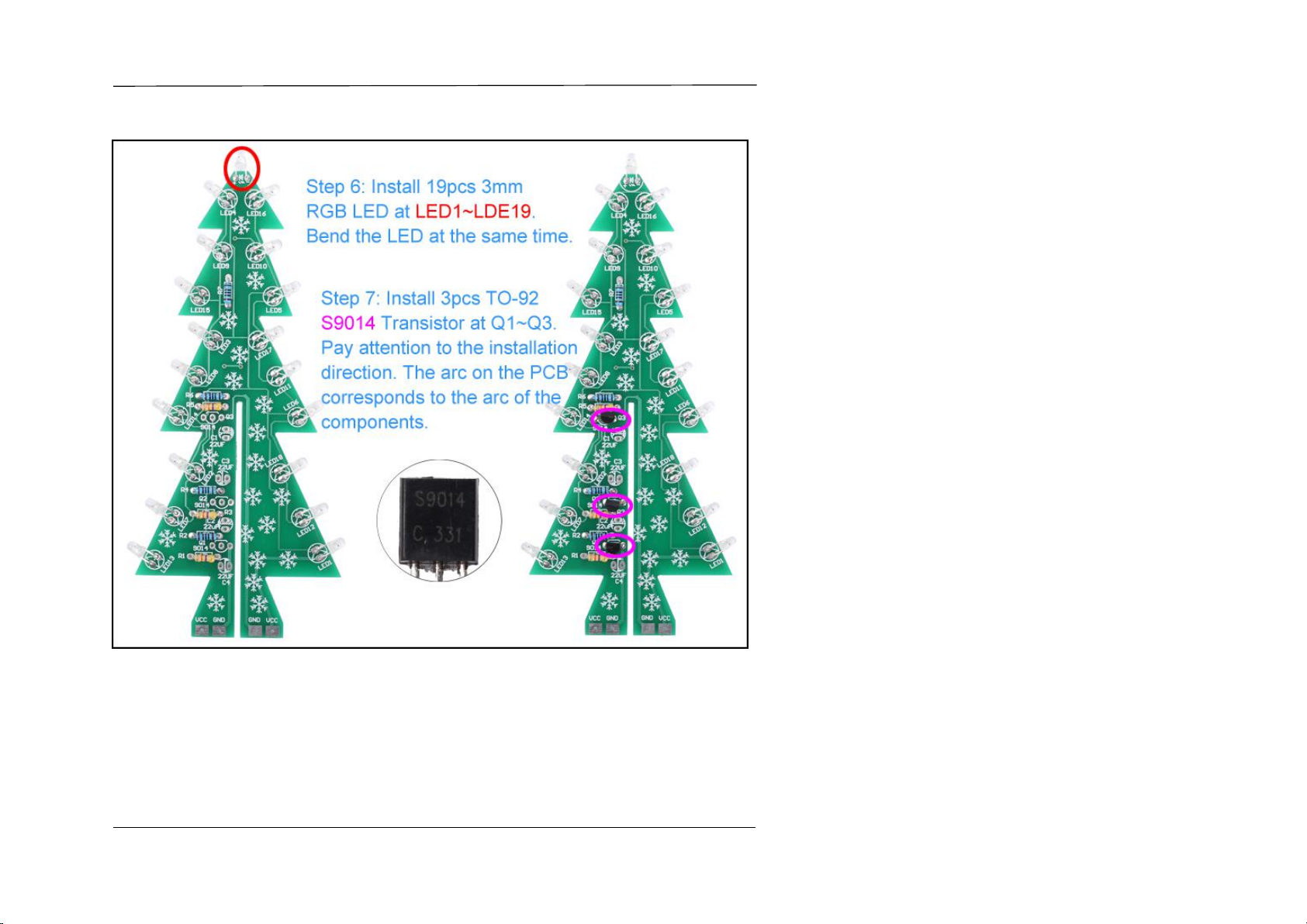
19>.Step 19: Install 2pcs TO-92 S8050 Transistor at Q1,Q2.Pay attention to the installation direction. The arc on the PCB corresponds to the arc of the
components.
20>.Step 20: Install 1pcs TO-92 BJ1522 Music IC at music.Pay attention to the installation direction. The arc on the PCB corresponds to the arc of the
components. Note: User does not need to install BJ1522 if does not need music.
21>.Step 21: Install 1pcs 22uF 25V Electrolytic Capacitor at C2.Pay attention to distinguish between positive and negative.The Longer pin is positive pole.
22>.Step 22: Install 1pcs 20Kohm Potentiometer at R7.
23>.Step 23: Install 1pcs Passive Buzzer at BELL.Note: User does not need to install buzzer if does not need music.Because it will keep playing music
and cannot be stopped after power ON.
24>.Step 24: Install 1pcs DC005 5.5*2.1mm Power Socket at JK1.
25>.Step 25: Install 1pcs DIP-8 LM358 at U2.There is a mark on one end of the LM358 and there is a mark on IC Socket where the LM358 can place
on.These two marks are corresponding to each other and are used to specify the installation direction of the LM358.
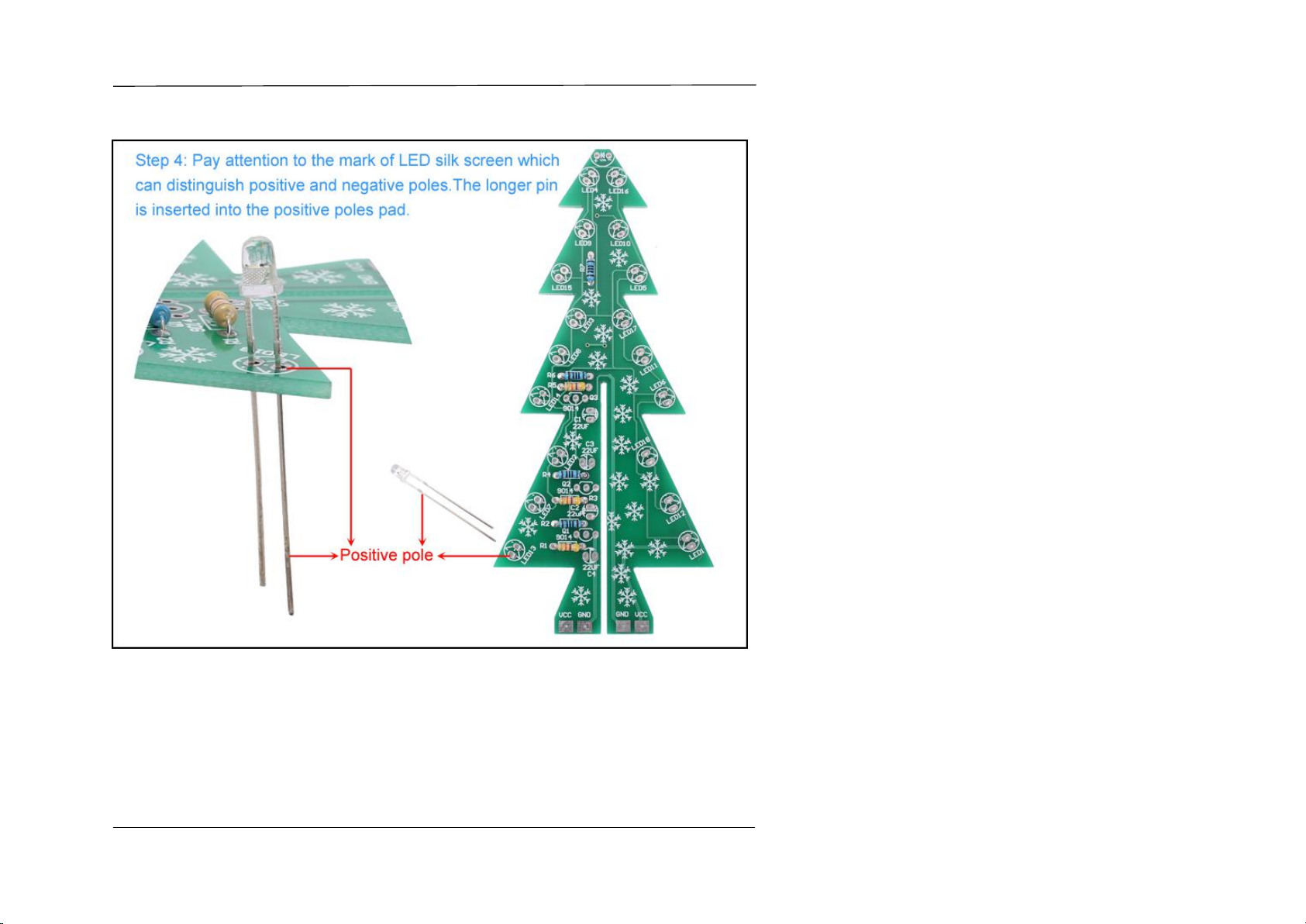
26>.Step 26: Pay attention to the mark of LED silk screen which can distinguish positive and negative poles.The longer pin is inserted into the positive
poles pad.
27>.Step 27: Install 18pcs 5mm Blue LED at D1~D18.
28>.Step 28: Install 1pcs DC3V-9V JS-30 DC Motor at motor.It is a DC motor, so there is no need to distinguish between positive and negative.
29>.Step 29: Fixed motor by 2pcs M3+10mm Screw and 2pcs M3 Nut.
30>.Step 30: Fix 2pcs M3+10mm Screw at 3mm holes by solder.(Note:Please do not use nuts to fix!)
31>.Step 31: Install 4pcs M3+25mm Copper Pillar and 4pcs M3+6mm Screw on Main PCB as a stand.
32>.Step 32: Install 2pcs 11*4*4mm Metal Spring at 3mm holes.They are used to provide work power for circular rotating PCB.
33>.Step 33: Assemble 2pcs tree PCB. Please follow the picture to combine.
34>.Step 34: Adjust height and position cooperate with Main PCB and make sure they fit properly.Then Fix 3pcs by 16 pads.
35>.Step 35: Install 4pcs M3+10mm Copper Pillar and 4pcs M3+6mm Screw on Bottom Round PCB which has two ring. The ring and Copper Pillar are
also used as circuits.
36>.Step 36: Fixed Bottom Round PCB on motor shaft by 1pcs M3+6mm Screw.
37>.Step 37: Fixed TOP Round PCB with tree on Bottom Round PCB by 4pcs M3+6mm Screw.Pay attention to the correspondence between VCC and
GND on two round PCB.
38>.Step 38: Tear off the protective film on the surface of Acrylic(Acrylic case is an optional accessory. Its installation has been completed if the kit
purchased does not have an acrylic case)