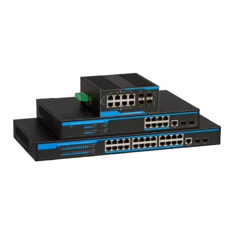
ICCN WX7020-1210G User manual

WX7020-1210G
Web User Guide
Supported Models:
ICC Networking Enterprise Gigabit Power-over-Ethernet Switch
Product Model: WX7020-1210G
WX7020-1210G
Web User Guide
Supported Models:
ICC Networking Enterprise Gigabit Power-over-Ethernet Switch
Product Model: WX7020-1210G
WX7020-1210G
Web User Guide
Supported Models:
ICC Networking Enterprise Gigabit Power-over-Ethernet Switch
Product Model: WX7020-1210G

Intended audience
This guide is designed to be used by network managers, IT administrators, and
technicians who are responsible for installing, networking equipment in enterprise
and service provider environments. Knowledge of telecommunication and
internet protocol (IP) technologies is assumed.
Documentation
The ICC icXchange®product and support documentation consists of a variety of
manuals, installation guides, videos, knowledge articles, sample designs,
troubleshooting, and FAQ guides to assist you with the deployment of your new
and innovative solution.
These and other documents are available for download at
http://www.intcomcorp.com/warranty-support/
To view PDF files, use Adobe Acrobat Reader®5.0 or newer. Download Acrobat
Reader for free from the Adobe website: http://www.adobe.com/products.
Find additional documentation at: http://www.iccnetworking.com.
Contact information
Phone: 844-242-9246
E-mail: [email protected]

Table of Content

Chapter 1: Product Introduction
1.1 Product Brief
The ICCN WX7020-1210G features 12 Ports of 10G SFP+ with 8 10/100/1000 Ports for
aggregation and enterprise management. The WX7020-1210G features 256 Gbps of wire speed
performance to allow non-blocking consolidation of your network ecosystems.
Included in the packaging:
1 WX7020-1210G
4 Rubber feet
2 Rack mount L-shaped brackets
4 Mounting screws
1 Line cord
Copper Ports
8 10/100/1000Base-TX ports
Fiber Ports
12 10G SFP+ Ports
Console
1 Console port
LEDs
PWR, PoE, Link, and Master
Input Voltage
Input voltage:48 VDC (48~ 56 V)
Power
Consumption
40W
Operating
Temperature
.0℃~40℃
Storage
Temperature
.-10℃~70℃
Humidity
20%~85% (non-condensing)
Fan
Noiseless Fan
The rear of the WX7020-1210G has one power receptacle for the line cord.
LEDs 10/100/1000 10G SFP+ Console Port
Ports Ports
Power receptacle
for the line cord
Noiseless Fan
Holes for mounting
bracket kit

Chapter 2: Hardware Installation
Installation Notice
Please follow all safety instructions to ensure proper operation of the Link5010AS-POE, your
physical security as well as the on-going warranty of the unit.
Environmental Requirements
The switch must be installed in a clean area with ample ventilation and free of
dust, otherwise, the switch may be damaged by electrostatic adherence.
Maintain the temperature and the humidity within the set environment.
The switch must be put in a dry and cool place. Please ensure sufficient spacing
around the switch for good air circulation.
The switch must work in the right range of power input.
The switch must be well grounded in order to avoid ESD damage and personal
physical injury.
The switch should avoid the sunlight perpendicular incidence. Keep the switch
away from heat sources and strong electromagnetic interference sources.
The switch must be mounted to a standard 19’’ rack or placed on a clean level
desktop.
Dust and Particles
Dust is harmful to the safe operation of the switch. Dust can lead to electrostatic adherence,
especially under low relative humidity, causing poor contact of metal connectors or contacts.
Electrostatic adherence will result not only in reduced product lifespan, but also increased chance
of communication failures. The recommended value for dust content and particle diameter in the
site is shown below:
Max Diameter (µm)
0.5
1
3
5
Max Density (particles/m³)
1.4×10⁵
7×10⁵
2.4×10⁵
1.3×10⁵
In addition, salt, acid and sulfide in the air are also harmful to the switch. Such harmful gases
will aggravate metal corrosion and the aging of some parts. The site should avoid harmful gases,
such as SO2, H2S, NO2, NH3and Cl2, etc. The table below details the threshold value.
Gas
Average (mg/m³)
Max (mg/m³)
SO2
0.2
1.5
H2S
0.006
0.03
NO2
0.04
0.15
NH3
0.05
0.15
Cl2
0.01
0.3

Temperature and Humidity
The switch installation site should maintain a desirable temperature and humidity. High-
humidity conditions can cause electrical resistance degradation or even electric leakage,
degradation of mechanical properties and corrosion of internal components. Extreme low relative
humidity may cause the insulation spacer to contract, making the fastening screw unsecure.
Furthermore, in dry environments, static electricity is liable to be produced and cause harm to
internal circuits. Temperature extremes can cause reduced reliability and premature aging of
insulation materials, thus reducing the switch’s working lifespan. In the hot summer, it is
recommended to use air-conditioners to cool the site. And the cold winter, it is recommenced to
use heaters. The recommended temperature and humidity are shown below:
Caution!
A sample of ambient temperature and humidity should be taken at 1.5m above the floor and
0.4m in front of the switch rack, with no protective panel covering the front and rear of the rack.
Short term working conditions refer to a maximum of 48 hours of continued operation and an
annual cumulative total of less than 15 days. Formidable operation conditions refers to the
ambient temperature and relative humidity value that may occur during an air-conditioning system
failure, and normal operation conditions should be recovered within 5 hours.
Power Supply
The power supply is an adopted module switched power.
Before powering on the power supply, please check the input power to ensure proper
grounding of the power supply system. The input power for the switch should be reliable and
secure; a voltage adaptor can be used if necessary. The building’s circuit protection system should
include in the circuit a fuse or circuit-breaker of no greater than 240 V, 10 A. It is recommended to
use a UPS for more reliable power supplying. .
Caution!
Improper power supply system grounding, extreme fluctuation of the input source, and
transients (or spikes) can result in larger error rate, or even hardware damage!
Preventing Electrostatic Discharge Damage
Static electric can cause damage to internal circuits, even the entire switch. Follow these
guidelines for avoiding ESD damage:
Ensure proper earth grounding of the device;
Perform regular cleaning to reduce dust;
Maintain proper temperature and humidity;
Always wear an ESD wrist strap and antistatic uniform when in contact with circuit
boards.
Anti-interference
All sources of interference, whether from the device/system itself or the outside environment,
will affect operations in various ways, such as capacitive coupling, inductive coupling,
electromagnetic radiation, common impedance (including the grounding system) and cables/lines
(power cables, signal lines, and output lines). The following should be noted:
Precautions should be taken to prevent power source interruptions;
Provide the system with a dedicated grounding, rather than sharing the grounding
with the electronic equipment or lightning protection devices.
Keep away from high power radio transmitters, radar transmitters, and high

frequency strong circuit devices.
Provide electromagnetic shielding if necessary.
Rack Configuration
The dimension of the switch is designed to be mounted on a standard 19’’ rack. Please ensure
good ventilation for the rack.
Every device in the rack will generate heat during operation, therefore vent and fans
must be provided for an enclosed rack, and devices should not be stacked close
together.
When mounting devices in an open rack, care should be taken to prevent the rack
frame from obstructing the switch ventilation openings. Be sure to check the
positioning of the switch after installation to avoid the aforementioned.
Installation Notice
Read through the installation instruction carefully before using the system. Make
sure the installation materials and tools are used and make sure the installation site
is well prepared.
During the installation, users must use the brackets and screws provided in the
accessory kit. Users should use the proper tools to perform the installation. Users
should always wear antistatic uniform and ESD wrist straps. Users should use
standard cables and connecters.
After the installation, users should clean the site. Prior to powering on the switch,
users should ensure the switch is well grounded. Users should also maintain the
switch regularly to extend the lifespan of the switch.
Security Warnings
When using SFP transceiver, do not stare directly at the fiber bore when the switch
is in operation. Otherwise the laser may cause eye damage.
Do not attempt to conduct the operations which can damage the switch or which
can cause physical injury.
Do not install, move or disclose the switch and its modules when the switch is in
operation.
Do not open the switch shell.
Do not drop metals into the switch. It can cause short-circuit.
Do not touch the power plug and power socket.
Do not place the tinder near the switch.
Do not configure the switch alone in a dangerous situation.
Use standard power sockets which have overload and leakage protection.
Inspect and maintain the site and the switch regularly.
Have the emergence power switch on the site. In case of emergence, switch off the
power immediately.
According to the required standards GB9254-2008 information technology
equipment radio disturbance limits and methods of measurement, information
technology equipment is divided into A level ITE and B level ITE.
A level ITE is the information technology equipment that satisfied A level limit but not
satisfied B level limit.
Note: For this kind of equipment, the sales should not be limited but it must include the
following statement in related direction for use.
Caution!
Potential risk include: Electric leakage, Power supply arcing, Power line breakage, Imperfect
earth, Overload circuit and Electrical short circuit. If electric shock, fire, electrical short circuit
occurs, please cut off the electricity supply and alarm rapidly.
All safety and installation requirements must be followed in order to keep warranty in place.
Any non-compliance can void warranty.

WX7020-1210G Installation
Installing the switch into a rack is very simple. The generic switch images demonstrates that you
add the switch mount ears to the switch first using the included screws. Once attached, place your
switch in the rack and mount with your rack screws (not included).
Step 1: Connect bracket ears to the switch Step2: Mount unit in the rack

Chapter 3: Web User Management
Network administrators can use a simple-to-configure web Graphical User Interface (GUI) to
manage and maintain the switch on their network.
Login web network management
The default Web login process and details are identified below. The default Web login information
includes:
Username: admin
Password: 'there is no password'
IP address of switch: 192.168.0.10
1. Connect the switch to a PC by using an Ethernet cable (not included) to connect the PC to one
of the switch’s Ethernet ports.
2. Configure the IP address for the PC and ensure that it can communicate with the switch. The
connection between the switch and PC can be done by a direct connection or through the
network. For example, change the IP address to 192.168.0.17 to ensure that the PC and switch
are in the same IP subnet.
3. Launch your PC’s web browser and type http://192.168.0.10 in the address bar. Press Enter.
4. On the login page, type admin in the Username field, and type admin in the Password field.
Click Login.
Username is 'admin'
Password is left blank

Successful Login:
Once you've logged in successfully, you'll be greeted by the initial overview page. This page
provides a short description of each section of the switch. The overview page is devided into three
sections:
Navigation Tree - Salmon box
Main Data Section - Red box
Tab - Green box
The Navigation sections are defined for you in the Main Data Section so you can quickly find the
desired feature needing to be edited.
Other GUI items to look for
Save Current Settings
Reload Current Page
Indicates another page is available
The second page contains additional ports

Chapter 4:
Introduction to the Navigation Menu
System:
Consider the System selection as the central starting point of your new 10G switch. You
can always start your navigation at the System page and select any number of features
from the Navigation on the left or the Tab at the top of the page.
--- General
Use the General screen to display descriptive information about the switch, or for quick
system identification.
--- Switch
Use the Switch Informationpage to display hardware/firmwareversion numbers forthe
mainboardandmanagementsoftware,aswellasthepowerstatusofthe system.

--- Default Priority
--- Time
UsetheTimemenutomanuallysetthesystemclock,ortoautomatically
configure the clock
through SNTP servers.
--- Console
Using the console page to setup parameters of the console terminal.

--- Default Priority
--- Web Manager
The Web Manager navigation gives you the ability to set your web session time out and refresh rates. You
might consider changing these parameters if you tend to be logged into the switch for long periods of time
while doing other tasks.
--- Telnet
Use the Telnet page to set Telnet connection
parameters.

--- Default Priority
--- User Manager
User management provides the ability to add different users by type of access method such as Console,
Telnet, Web GUI, and Privileged Password.
To edit a user's access to a specific type of method you need to follow the below instructions for
each method.
1.Console User Manage :
Modify the console username and password
2.Telnet User Manage:
Modify the telnet username and password
(Note: before you use telnet connections, you must have configured username and
password)
3.Web User Manage:
Modify the web username and password
4.Privileged User Manage:
Modify the privileged password.
--- CPU Utilization
The CPU Utilization page displays how much processing power of the CPU is being used.
Performance reading are live.

--- Default Priority
--- Memory Status
Use the Memory Status page to display memory utilization parameters
--- File
Use the File menu to transfer runtime code or configuration settings,or to configure the
automatic upgrade function.

--- Default Priority
--- Reset
Use the Reset page to restarts the switch immediately, at a specified time, after a
specified delay, or at a periodic interval.
Reset will power cycle the switch while keeping current settings
Save will save all current settings
Factory Default Settings, Reboot will reset the switch to it's original factory default setting.
NOTE: When using Factory Default Settings, Reboot, please make sure this is what you would like to
do. All current settings will be ERASED and only the original factory settings will be restored. ALL
previous settings including user management and passwords will no longer be enforces.

--- Default Priority
Chapter 5:
Introduction to the Tab Menu
The menu table across the top of the web user interface is a very useful tool intended for use by novice as
well as experienced network engineers. The Tab Menu starts with the System interface which provides a
detailed navigation and definition of each feature and its location.
System
The Tab Menu can be found at the top of the GUI
Once you're in System you can view all features prior to use as well as their definitions and location.
Simply scroll down to view the other features and details.
If you select any feature from the Tab Menu you will see the Navigation Tree to the left change, opening up
features for your configuration. You will always know where you are located in the tree because it is
notated just under the Tab Menu.

--- Default Priority
Interface
The first tab on the menu is Interface. Interface provides configuration access for ports, power, features,
and a host of other statistics.
For example, Port Configuration is simple of clicking General in the left Navigation menu while on the
Interface Tab.
--- Green Ethernet
UsetheGreenEthernetpagetoadjustthepowerprovidedtoportsbasedonthe length of
the cable used to connect to other devices.
Interface is selected
The Navigation Tree shows what
features are available for configuration
General is selected under Port
You can now edit port configurations

--- Default Priority
--- Statistics
Use the Statistics page to show Interface, Etherlike, and RMON port statistics.
--- Chart
Use the Chart page to show Interface, Etherlike, andRMON port statistics in graphic
form.

--- Default Priority
-- Trunk
Use the Trunk menu to configure static or dynamic trunks, or to display statistics
on network traffic.
--- Static
Use the Static page to create a trunk, add port members, and configure connection
parameters.
First you must decide on the Trunk ID by selecting 1 - 32 and click the 'ADD' button/
Once selected you can then decide on what type of Hash you'd like to use per trunk.
Once selected, you can continue to add more trunk ports.
Table of contents
Other ICCN Switch manuals
Popular Switch manuals by other brands

NETGEAR
NETGEAR ProSafe XS712T installation guide

SMART
SMART DPA 21 user manual

Cisco
Cisco AJ732A - MDS 9134 Fabric Switch Configuration guide

Crestron
Crestron DigitalMedia DMC-CATO-HD Specifications

Brocade Communications Systems
Brocade Communications Systems ICX 7450 series Hardware installation guide

ZPA
ZPA TSA 01262 Instructions for use