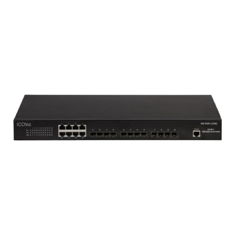
ICCN WP6000 Series User manual

WP6000 Series Switches
Installation Guide
Supported Models:
ICC Networking Enterprise Gigabit Power-over-Ethernet Switch
Product Model: Link6010-8POE, Link6026-24POE, and Link6012IND-8POE
WP6000 Series Switches
Installation Guide
Supported Models:
ICC Networking Enterprise Gigabit Power-over-Ethernet Switch
Product Model: Link6010-8POE, Link6026-24POE, and Link6012IND-8POE
WP6000 Series Switches
Installation Guide
Supported Models:
ICC Networking Enterprise Gigabit Power-over-Ethernet Switch
Product Model: Link6010-8POE, Link6026-24POE, and Link6012IND-8POE

Intended audience
This guide is designed to be used by network managers, IT administrators, and
technicians who are responsible for installing, networking equipment in enterprise
and service provider environments. Knowledge of telecommunication and internet
protocol (IP) technologies is assumed.
Documentation
The ICC icXchange®product and support documentation consists of a variety of
manuals, installation guides, videos, knowledge articles, sample designs,
troubleshooting, and FAQ guides to assist you with the deployment of your new and
innovative solution.
These and other documents are available for download at
http://www.intcomcorp.com/warranty-support/
To view PDF files, use Adobe Acrobat Reader®5.0 or newer. Download Acrobat
Reader for free from the Adobe website: http://www.adobe.com/products.
Find additional documentation at: http://www.iccnetworking.com.
Contact information
Phone: 844-242-9246
E-mail: [email protected]

ICC Networking's WP6000 series PoE switches are multi-port 10/100/1000Base-T
Ethernet switches used to build high-performance and intelligent switched
workgroup networks. This switch is a store-and-forward device that offers low
latency for high-speed networking. The WP6000 series also features a “store-and-
forward” switching scheme that allows the switch to auto-learn and store source
addresses in a 8K-entry MAC address table. The switch is targeted at workgroup,
department or backbone computing environments.

WP6000 Series Overview
Link6010-8POE
Package contents include the following: PoE switch
AC power cord
Two (2) rack-mount pallet and Six (6) screws
Four (4) adhesive-backed rubber feet
Support Card
Link6026-24POE
Package contents include the following: PoE switch
AC power cord
Two (2) rack-mount pallet and Six (6) screws
Four (4) adhesive-backed rubber feet
Support Card
IMPORTANT: If any item is missing or damaged, please contact your local dealer or
reseller for service.
The Front Panel
The front panel consists of LED Indications and eight (8) or twenty-four (24)
10/100/1000M adaptive RJ-45 ports and 1 Console port+2 Gigabit SFP ports
combine.
LED Indicators
Per Device: Power
Per Port: LINK/ACT (Link/Activity) Per PoE Port: PoE
Link6010-8POE
Link6026-24POE
Rear of each switch

Quick considerations when troubleshooting
This section is intended to help solve the most common issues with the PoE Switch
Incorrect connections
Every port on these switches can automatically detect either straight or crossover
cables when you link it with other Ethernet devices but other devices may require a
specific cable type (depending on the device). Make sure to confirm cable
requirements from the device vendor and choose the appropriate cable to connect
between the units. The RJ-45 connectors should use correct UTP or STP cable,
10/100Mbps port use 2-pairs twisted cable. If the RJ-45 connector is not correctly
pinned then the link will fail.
Faulty or loose cables
Look for loose or obviously faulty connections. If they appear to be OK, make sure
the connections are snug. If that does not correct the problem, try a different cable,
utilize cable testing devices, and other methods to confirm cable integrity.
Non-standard cables
Non-standard and incorrectly terminated cables may cause numerous network
collisions and other network problems, and can seriously impair network
performance. A cable tester is the recommended tool for network installation.
Utilization of non-standard cables could negatively impact product warranty. Be
sure that length of any twisted-pair connection does not exceed 100 meters (328
feet). We suggest using Category 5e cable when connection to power a device.
Improper Network Topologies
It is important to make sure that you have a valid network topology. Common
topology faults include excessive cable length and too many repeaters (hubs)
between end nodes. In addition, you should make sure that your network topology
contains no data path loops. Between any two ends nodes, there should be only one
active cabling path at any time. Data path loops will cause broadcast storms that will
severely impact your network performance.
Diagnosing LED Indicators
To assist in identifying problems, the switch can be easily monitored through panel
indicators, which describe common problems the user may encounter and where
the user can find possible solutions. If the LED display detection isn’t correct, please
unplug then plug in the cable again.
If the power indicator does not light when the power cord in plugged in, you may
have a problem with the power outlet or power connections, power losses, or surges
at power outlet. If the problem still cannot be resolved, please contact the local
dealer for assistance.

Chapter 1 Graphical User Interface Basics
1、WEB Access features
The ICCN WP6000 series enterprise switches web user interface provides users with a
simple to use web-based tool to configure the many features of the device. Users can
access the WP6000 series to configure a variety of features including but not limited to:
1. Network: Spanning Tree, MAC Address control, port configuration, etc.
2. Security: VLANs, Radius, 802.1x, Password, etc.
3. Content Control: Quality of Service. Layer 3 aware, ACL, etc.
4. Management: Upload/Download, Troubleshooting, etc.
2、Brower requirements
Hardware&Software
system requirements
CPU
Pentium 586 above
Memory
128MB above
Resolution
800x600 above
Color
256 colors above
Browser
Google Chrome®, Apple Safari®, Firefox®
Operating system
Currently supported Microsoft operating system, Linux and
Unix

3、Starting an initial web session
To start a web user session the user must log into the WP6000 series switch by confirming the
following:
1. For initial configuration you may connect directly to the switch once the PC is within
the same IP address range as the switch
2. The switch VLAN1 interface IP address is 192.168.0.1,
3. The subnet mask is 255.255.255.0.
4. Enter the IP address into the web browser and use the following user/password
User name: admin
Password:
Note: Upon initial set up from factory, there is no password so just click
'ok' to proceed. Once in the interface you must set a password on the
unit.
4、WEB page elements
The graphical user interface (GUI) page is made up of three parts:
1. Title - Device quick view representation for each port and port status
2. Navigation Tree - List of configurable features
3. Main - Configuration and data entry section based on the Navigation selections

5、How to use the Navigation Tree
The navigation tree organizational structure is simple to use for a quick view of all possible features
and protocols that can be adjusted by the WP6000 series switches.
The Navigation Tree is located on the left of each page in simple to understand folders.
The Navigation Tree allows users to quicklyfind the feature category they need and within each
folder category, users are presented with more detailed features. According to a different web page
functionality can be divided into different groups, each including one or more pages. Most of the
navigation tree is in the name of the corresponding web page folder.
6、Action button overview
Action buttons are used to execute specification items such as save or delete.
Form 2 outlines the specific role of each button:
Form 2:
BUTTON
MEANING
Refresh
Updates all fields on the page
Apply
Updates and saves to memory all values. This action overwrites
previous values.
Delete
Delete the current record
Help
Opens help pages to view different configuration instructions

7、Error messages
If the switch WEB server error occurs while processing a user's requests,
a dialog box in the corresponding error message will be displayed. For
example, the an error message dialog box is shown on the right.
8、The Main entry Field
Selecting different features from the Navigation bar will open different configuration options within
the Main entry fields to the right. The open sections for those fields can be anything based on the
selected Navigation feature as shown in the image below.
The Main entry field is organized with different rows, tables, and selections options based on the
selected feature that's being configured. The above example in Figure 5 is specific to Simple
Network Management Protocol (SNMP) configuration.
SNMP configuration allows the user to enter data into one row at a time. The very first entry will
show 'New' in the Item row until data is entered. Once entered and applied the WP6000 series
switch software will add the new data to the unit with an updated Item number. Future SNMP
configure queries will show all the Item lists allowing users to select previously entered values for
deletion or select 'New' in the Item drop box to add new parameters.

Status Field
Chapter 2 Quick Stats
The most viewed section of the interface is the Port Statistics field. It's important to know the
location of per port details so as you complete configuration details, it can be confirmed what types
of data each port is passing. Therefore, we're demonstrating that location first.
To reach the Port Statistics Information section, in the Navigation bar select Port Configuration
and then select Port Statistics. Once completed, the Main information screen will show all details
on a per port basis. Select the desired port to be reviewed from the 'Port' dropdown box to the left
within the Main section. The fields are read only as shown below.

-
1111
-
Chapter 3 GUI Configuration Options
System Configuration:
(1)Basic information page
Within the System Configuration folder is the Basic Information option which shows the detail about
the installed product. This includes basic switch information, connected ports, and users can add notes
about the system.
System Description - Switch version and firmware
System Object ID - A network identity management parameter
System Version - Current firmware
Num Network Interfaces - Number of connected ports
System Start - Displays the switch run time from start to the present time
System Name - Name of the switch in the network. Users can edit with an internal tracking ID
System Location- The physical location of the switch. User can edit with internal tracking ID
System Contact -The contact persons responsible for the network. User can edit with internal tracking ID
Basic information
Page
(2)Serial port information page
A serial connection can be use to access the switch command line interface. The Serial Port
configuration page shows the serial baud rate, parity code, stop bits, and flow control.
Serial port information page
-
1111
-
Chapter 3 GUI Configuration Options
System Configuration:
(1)Basic information page
Within the System Configuration folder is the Basic Information option which shows the detail about
the installed product. This includes basic switch information, connected ports, and users can add notes
about the system.
System Description - Switch version and firmware
System Object ID - A network identity management parameter
System Version - Current firmware
Num Network Interfaces - Number of connected ports
System Start - Displays the switch run time from start to the present time
System Name - Name of the switch in the network. Users can edit with an internal tracking ID
System Location- The physical location of the switch. User can edit with internal tracking ID
System Contact -The contact persons responsible for the network. User can edit with internal tracking ID
Basic information
Page
(2)Serial port information page
A serial connection can be use to access the switch command line interface. The Serial Port
configuration page shows the serial baud rate, parity code, stop bits, and flow control.
Serial port information page

-
1212
-
(3)User management page
The User Management page is important because it controls name and password access to the device
and by extension your network. As shown in the image below, you can edit the password as well as
provide different users different types of passwords.
Passwords are case-sensitive, and can be up to 16 characters. To properlychange a password, the
user must enter the new password twice. Click the Apply button to complete the new password
activation. Users will need to re-login into the switch using the new password in order to continue
editing other configuration functions.
The ICCN WP6000 series enterprise switches support multi-user access to the system; however, it
is not enabled by default. The user must enable this features should they wish to use it.
When adding multiple users to the system, if the users are privileged (executed by selecting from the
drop box to the right) then Multi-user management is effectively enabled. If all additional users are
deleted, then it automatically closes the use of this feature.
When the multi-user management feature is enabled, the master password will not take effect, log
Telnet and the Web will require a multi-user user name and password authentication. When the
multi-user management function is turned off, at this time if the configured then the master password
is required in order to log on to Telnet and Web GUI.
User Management and Password
-
1212
-
(3)User management page
The User Management page is important because it controls name and password access to the device
and by extension your network. As shown in the image below, you can edit the password as well as
provide different users different types of passwords.
Passwords are case-sensitive, and can be up to 16 characters. To properlychange a password, the
user must enter the new password twice. Click the Apply button to complete the new password
activation. Users will need to re-login into the switch using the new password in order to continue
editing other configuration functions.
The ICCN WP6000 series enterprise switches support multi-user access to the system; however, it
is not enabled by default. The user must enable this features should they wish to use it.
When adding multiple users to the system, if the users are privileged (executed by selecting from the
drop box to the right) then Multi-user management is effectively enabled. If all additional users are
deleted, then it automatically closes the use of this feature.
When the multi-user management feature is enabled, the master password will not take effect, log
Telnet and the Web will require a multi-user user name and password authentication. When the
multi-user management function is turned off, at this time if the configured then the master password
is required in order to log on to Telnet and Web GUI.
User Management and Password

-
1313
-
(4)Safe (Security)Management Page
The Safe (Security) management configuration page provides full admin management of all
management services including telnet, web GUI and SNMP, enable/disable services, attached to
services like IPACL grouping ,and the implementation of the source IP address control, control access
to the host of these services. By default, the WP6000 series telnet, GUI, and SNMP services are
open with no ACL filtering.
The network administrator can limit access to services based on internal policies. If the
administrator gives access to a specified host user to access one or several services, they can use ACL
filtering to provide access to one or several service options.
To configure a service, users must first select the service in the first column. Once selected, you must
enable the service from the dropdown menu under Management State. The final step is to confirm the
ACL Group you wish to add this service type to.
Safe (Security) Management
(5)Configure the current page
The Current Configuration page is designed to provide a confirmation of the configuration while
giving the administrator the ability to save that configuration to the switch. Once saved, it will delete
any previous configurations. This action is time consuming so it's recommended to conduct these
during off peak hours.
Note: The username and password entries seem to look like Asian characters, but they do not
represent a language and are used for deep encryption.
Current Configuration P
age
-
1313
-
(4)Safe (Security)Management Page
The Safe (Security) management configuration page provides full admin management of all
management services including telnet, web GUI and SNMP, enable/disable services, attached to
services like IPACL grouping ,and the implementation of the source IP address control, control access
to the host of these services. By default, the WP6000 series telnet, GUI, and SNMP services are
open with no ACL filtering.
The network administrator can limit access to services based on internal policies. If the
administrator gives access to a specified host user to access one or several services, they can use ACL
filtering to provide access to one or several service options.
To configure a service, users must first select the service in the first column. Once selected, you must
enable the service from the dropdown menu under Management State. The final step is to confirm the
ACL Group you wish to add this service type to.
Safe (Security) Management
(5)Configure the current page
The Current Configuration page is designed to provide a confirmation of the configuration while
giving the administrator the ability to save that configuration to the switch. Once saved, it will delete
any previous configurations. This action is time consuming so it's recommended to conduct these
during off peak hours.
Note: The username and password entries seem to look like Asian characters, but they do not
represent a language and are used for deep encryption.
Current Configuration P
age

-
1414
-
(6)ConfigurationFilepage
The Configuration Filepage is the saved configuration from the Current Configuration and allows
users to download the file for future use. This file can be used as a back-up or to duplicate to other
WP6000 series switches. The WP6000 series will always keep the factory default settings within
the system. Therefore, if the administrator needs to reset the switch to factory default, they can.
The Download button is for easy download of the configuration file. After clicking download a pop up
dialog box will come up to confirm user options to save and download the configuration file named
switch.cfg.
The Delete key provides the option to delete the configuration file. A pop up box will ask for
confirmation of selected task.
Configuration File
(7)File Upload
The File Upload page allows users to upload a configuration file and/or mapping files to the switch.
Clicking the Choose File button allows the user to browse for the designated file for upload. Once found
and selected, users then simply click the Upload button and the file is uploaded. This action may take a
few minutes so do not log out of the session until complete.
All configuration file extension must be . cfg, and image file must be as provided by the manufacturer
withthe file name extension of .img.
File Upload
-
1414
-
(6)ConfigurationFilepage
The Configuration Filepage is the saved configuration from the Current Configuration and allows
users to download the file for future use. This file can be used as a back-up or to duplicate to other
WP6000 series switches. The WP6000 series will always keep the factory default settings within
the system. Therefore, if the administrator needs to reset the switch to factory default, they can.
The Download button is for easy download of the configuration file. After clicking download a pop up
dialog box will come up to confirm user options to save and download the configuration file named
switch.cfg.
The Delete key provides the option to delete the configuration file. A pop up box will ask for
confirmation of selected task.
Configuration File
(7)File Upload
The File Upload page allows users to upload a configuration file and/or mapping files to the switch.
Clicking the Choose File button allows the user to browse for the designated file for upload. Once found
and selected, users then simply click the Upload button and the file is uploaded. This action may take a
few minutes so do not log out of the session until complete.
All configuration file extension must be . cfg, and image file must be as provided by the manufacturer
withthe file name extension of .img.
File Upload

-
1515
-
(8)System reset page
The System Reset page can be used to restart the switch by simply clicking the Reset button. When
the Reset is selected a pop up dialog box will prompts the user to confirm the restart. If OK is selected,
then the unit will begin the restart process. Your session will end and require the user to log back into
the device.
Note: Please make sure you saved your setting and downloaded any files you required.
System Reset
-
1515
-
(8)System reset page
The System Reset page can be used to restart the switch by simply clicking the Reset button. When
the Reset is selected a pop up dialog box will prompts the user to confirm the restart. If OK is selected,
then the unit will begin the restart process. Your session will end and require the user to log back into
the device.
Note: Please make sure you saved your setting and downloaded any files you required.
System Reset

-
1616
-
Port Configuration
(1)Common Configuration (Port configuration/Show)
The Common Configuration (port config.) page provides at-a-glance details about each port of the
WP6000 series switch. The port configuration page provides port controls including
enabling/disabling a port, setting port speed, and the ability of the port to auto-negotiate speeds.
To configure a specific port simply select the port number via the Port dropdown box. Users can then
decide if they need the port up/down or to change speed characteristics.
Common Configuration (Port Configuration/Show)
(2)Port Statistics Page
The Port Statistics information page provides per port details about the type of IP data traffic flowing
through that specific port.
To view a particular port, users need to select the appropriate port name in the port drop-down menu.
Users will view all
statistics for
send and receive packets on this port.
Port Statistics Page
-
1616
-
Port Configuration
(1)Common Configuration (Port configuration/Show)
The Common Configuration (port config.) page provides at-a-glance details about each port of the
WP6000 series switch. The port configuration page provides port controls including
enabling/disabling a port, setting port speed, and the ability of the port to auto-negotiate speeds.
To configure a specific port simply select the port number via the Port dropdown box. Users can then
decide if they need the port up/down or to change speed characteristics.
Common Configuration (Port Configuration/Show)
(2)Port Statistics Page
The Port Statistics information page provides per port details about the type of IP data traffic flowing
through that specific port.
To view a particular port, users need to select the appropriate port name in the port drop-down menu.
Users will view all
statistics for
send and receive packets on this port.
Port Statistics Page

-
1717
-
(3)Flow control page
Flow Control information is provided as a quick view for all ports or on a per port basis. Users can
enable and disable Flow Control on each port from this single page.
To enable/disable per port Flow Control, users just select the port number they'd like to control
from the upper Port dropdown box. Once the port is selected, then select off/on from the dropdown
menu.
Flow Control
(4)Broadcast Storm
Broadcast Storm Control section is used to configure per port broadcast packets, multicast packets
and DLF packet when ensuring suppression policy.
First the user can select the desired port from the Port dropdown menu. Once the port is selected,
you can decide which type of suppression (Broadcast, Multicast, DLF) control is needed. Select the
type and click the dropdown to turn that policy on or off. Once completed, select the Rate Limit
required per control type. Click Apply once completed.
Broadcast Storm Control
-
1717
-
(3)Flow control page
Flow Control information is provided as a quick view for all ports or on a per port basis. Users can
enable and disable Flow Control on each port from this single page.
To enable/disable per port Flow Control, users just select the port number they'd like to control
from the upper Port dropdown box. Once the port is selected, then select off/on from the dropdown
menu.
Flow Control
(4)Broadcast Storm
Broadcast Storm Control section is used to configure per port broadcast packets, multicast packets
and DLF packet when ensuring suppression policy.
First the user can select the desired port from the Port dropdown menu. Once the port is selected,
you can decide which type of suppression (Broadcast, Multicast, DLF) control is needed. Select the
type and click the dropdown to turn that policy on or off. Once completed, select the Rate Limit
required per control type. Click Apply once completed.
Broadcast Storm Control

-
1818
-
(5)Port Rate Limit
Port Rate Limiting section is used to specify the rate at which IP data is sent and received. This is
slightly different than just adjusting the speed of the port.
To configure per port limits first select the port from the Port dropdown box in the upper left
corner. Once the port is selected, you can enter the size value for Sending and/or Receiving Rate
Control. Once you've made a selection, click Apply to apply the setting. The Main screen will
refresh and show the updated changes.
The Cancel button is used to cancel the corresponding data packet to send bandwidth control.
Selecting Cancel will automatically zero out the setting for that port and does not require the user to click Apply.
Port Rate Limiting
(6)Protected Port
The Protected Port page is used to turn on or off per port protection.
Protected Ports cannot communicate with other Protected Ports. They can only communicate with
non-protected ports.
Protected Port
-
1818
-
(5)Port Rate Limit
Port Rate Limiting section is used to specify the rate at which IP data is sent and received. This is
slightly different than just adjusting the speed of the port.
To configure per port limits first select the port from the Port dropdown box in the upper left
corner. Once the port is selected, you can enter the size value for Sending and/or Receiving Rate
Control. Once you've made a selection, click Apply to apply the setting. The Main screen will
refresh and show the updated changes.
The Cancel button is used to cancel the corresponding data packet to send bandwidth control.
Selecting Cancel will automatically zero out the setting for that port and does not require the user to click Apply.
Port Rate Limiting
(6)Protected Port
The Protected Port page is used to turn on or off per port protection.
Protected Ports cannot communicate with other Protected Ports. They can only communicate with
non-protected ports.
Protected Port

-
1919
-
(7)Port Learning restrain page
The WP6000 series enterprise switches are able to learn some or all of a MAC Address details. Port
Learning Limit allows the user to restrict how much the device has to learn based on what the
administrator's internal policies require.
The learning range can be between 0-8191. The switch default is set to the maximum value of 8191.
Port Learning Limit
-
1919
-
(7)Port Learning restrain page
The WP6000 series enterprise switches are able to learn some or all of a MAC Address details. Port
Learning Limit allows the user to restrict how much the device has to learn based on what the
administrator's internal policies require.
The learning range can be between 0-8191. The switch default is set to the maximum value of 8191.
Port Learning Limit

-
2020
-
(8)Port Trunking configuration
Port Trunking is used to provide many users with access to a network by sharing multiple lines or
frequencies. Similar to a tree with one trunk but many branches, port trunking can enable network
administrators to see IP data traffic from various VLANs via the one port.
The WP6000 series port trunking configuration consists of four parts:
Port Trunking ID Selection
Port Trunking Method Selection
Configuration Ports
Group Members Port
To create or modify the port trunking, the user need to select a port trunking ID, port trunking ID
from 1 to 3. The user clicks the list box the appropriate port trunking ID, the port trunking of
information displayed in the group port. To create a Trunk group, select the appropriate ID in the
port trunking ID, click the button "Trunk ID Settings."
Port Trunking ID Selection:
You must first select a Trunk Group ID from the list of 8 options which will initially show as being 'Uncreated'
in the web interface. This device supports up to 8 different trunk groups that can be created. In the below
example we selected '0001' or '1.'
WP6000series can trunk based on source mac, destination mac, source and destination mac, source ip, destination
ip and source and destination ip
-
2020
-
(8)Port Trunking configuration
Port Trunking is used to provide many users with access to a network by sharing multiple lines or
frequencies. Similar to a tree with one trunk but many branches, port trunking can enable network
administrators to see IP data traffic from various VLANs via the one port.
The WP6000 series port trunking configuration consists of four parts:
Port Trunking ID Selection
Port Trunking Method Selection
Configuration Ports
Group Members Port
To create or modify the port trunking, the user need to select a port trunking ID, port trunking ID
from 1 to 3. The user clicks the list box the appropriate port trunking ID, the port trunking of
information displayed in the group port. To create a Trunk group, select the appropriate ID in the
port trunking ID, click the button "Trunk ID Settings."
Port Trunking ID Selection:
You must first select a Trunk Group ID from the list of 8 options which will initially show as being 'Uncreated'
in the web interface. This device supports up to 8 different trunk groups that can be created. In the below
example we selected '0001' or '1.'
WP6000series can trunk based on source mac, destination mac, source and destination mac, source ip, destination
ip and source and destination ip
This manual suits for next models
3
Table of contents
Other ICCN Switch manuals
Popular Switch manuals by other brands

United Electric Controls
United Electric Controls 117 Series Installation and maintenance instructions

Avaya
Avaya ERS 3500 Series Regulatory information

D-Link
D-Link DMS-105 Quick installation guide

HP
HP SN6000B Hardware reference guide

LevelOne
LevelOne GSW-2472TGX user manual

Renkforce
Renkforce 1208454 operating instructions