ICON A5 Owner's manual

PILOT’S
OPERATING
HANDBOOK
MODEL A5
FOUNDER’S EDITION
ICON Aircraft / 2141 ICON Way, Vacaville, CA 95688
Publication ICA012347, Issue A3
Airplane Registration Number:_________________________
Airplane Serial Number:________________________________
Date: 22 August 2018

II
ICON Aircraft, Inc.
2141 ICON Way
Vacaville, CA 95688
https://www.iconaircraft.com
All rights reserved. No part of this manual may be
reproduced or copied in any form or by any means
without written permission of ICON Aircraft, Inc.

RECORD OF MANUAL/HANDBOOK REVISIONS / ISSUE A3 III
ISSUE A3 ICON A5 / PILOT’S OPERATING HANDBOOK
RECORD OF MANUAL/HANDBOOK REVISIONS
This section gives a record of the Pilot’s Operating Handbook
revisions in the current issue series (Issue A, Issue B, etc.). Further
description of the revisions by issue and chapter can be found
below.
ISSUE A3
The following are a list of revisions for Issue A3.
Chapter 2
• Corrected typo in the word ‘supplying’ in the warning for
Minimum Load Rating of Cargo Restraints (Pilot Supplied)
• Updated text of Environmental Limitations
• Revised reference to FAA exemption number
• Corrected graphic font error in Secure Loose Objects placard
• Updated the ELT Remote Switch placard
Chapter 4
• Updated text of Step Taxi/Normal Takeoff—Water
Chapter 7
• Updated text of Flight Controls
• Updated placard in ELT Remote Control and Audio Alert Indi-
cator
Chapter 8
• Updated text of Cleaning and Care related to Corrosion Inhib-
itor
Chapter 9
• Updated FAA Exemption
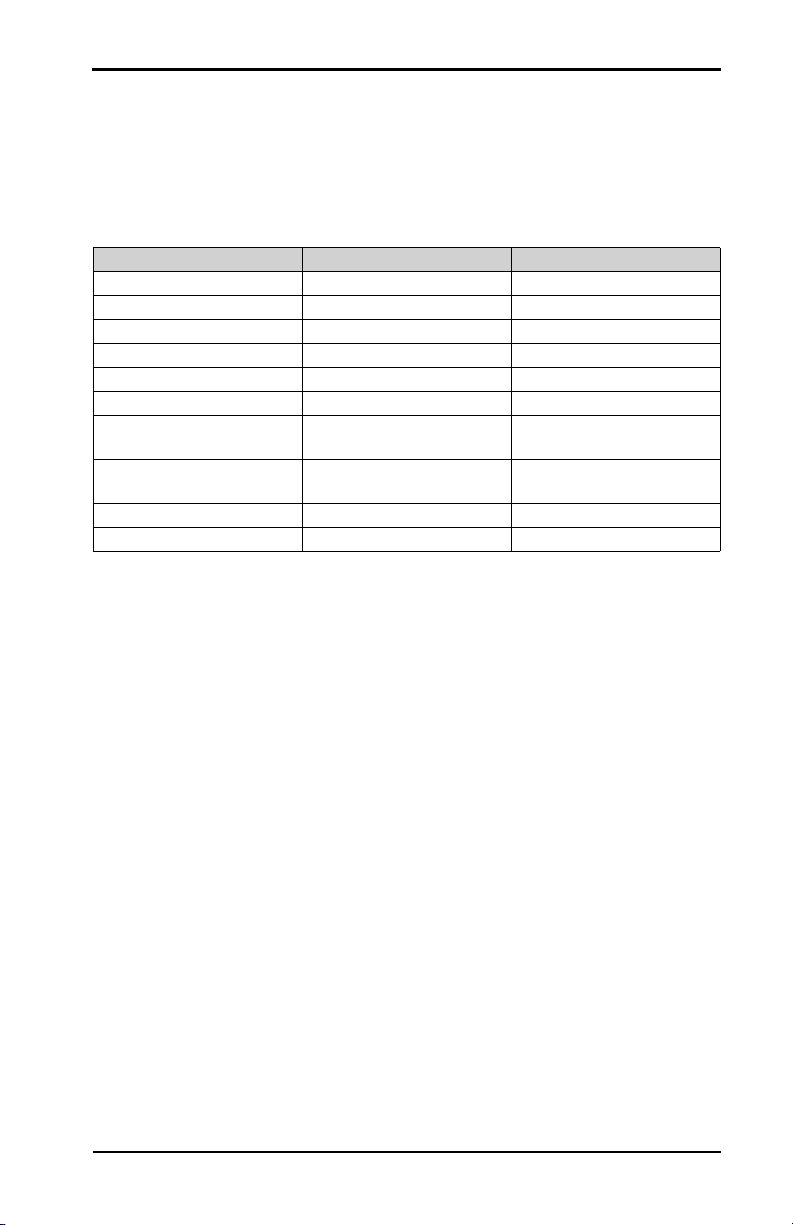
Issue Date Chapter(s) Added By
A 02 August 2017 All ICON Aircraft
A1 16 February 2018 3,4,7,9 ICON Aircraft
A2 11 April 2018 2,3,4,7,9 ICON Aircraft
A3 22 August 2018 2,4,7,8,9 ICON Aircraft

IV RECORD OF MANUAL/HANDBOOK REVISIONS / ISSUE A2
ICON A5 / PILOT’S OPERATING HANDBOOK ISSUE A3
ISSUE A2
The following are a list of revisions for Issue A2.
Chapter 2
• Changed Complete Aircraft Parachute to ICON Parachute
System (IPS)
Chapter 3
• Changed Complete Aircraft Parachute to ICON Parachute
System (IPS)
Chapter 4
• Changed Complete Aircraft Parachute to ICON Parachute
System (IPS)
Chapter 7
• Changed Complete Aircraft Parachute to ICON Parachute
System (IPS)
Chapter 9
• Changed Complete Aircraft Parachute to ICON Parachute
System (IPS)
ISSUE A1
The following are a list of revisions for A1.
Chapter 3
• Small formatting changes
• Updated Electrical Fire in Flight
• Added Box-Canyon Reversal
Chapter 4
• Updated Before Cockpit Entry
Chapter 7
• Correct typos
• Updated ICON Parachute System
Chapter 9
• Updated ICON Parachute System

RECORD OF MANUAL/HANDBOOK REVISIONS / ISSUE A V
ISSUE A3 ICON A5 / PILOT’S OPERATING HANDBOOK
ISSUE A
The following are a list of revisions for Issue A.
All Chapters
• Initial release of Founder’s Edition POH

VI RECORD OF MANUAL/HANDBOOK REVISIONS / ISSUE A
ICON A5 / PILOT’S OPERATING HANDBOOK ISSUE A3

LIST OF EFFECTIVE CHAPTERS / VII
ISSUE A3 ICON A5 / PILOT’S OPERATING HANDBOOK
LIST OF EFFECTIVE CHAPTERS
The table below shows the current, effective chapters and dates in
this revision of the handbook (see previous section). The applicable
handbook issue is listed at the bottom corner of this page for
reference.
Chapter Change Date
0. Introduction A0 02 August 2017
1. General Information A0 02 August 2017
2. Limitations A2 22 August 2018
3. Emergency Procedures A2 11 April 2018
4. Normal Procedures A3 22 August 2018
5. Performance A0 02 August 2017
6. Weight, Balance, and
Equipment List A0 02 August 2017
7. Description of Airplane
and Systems A3 22 August 2018
8. Handling and Servicing A1 22 August 2018
9. Supplements A3 22 August 2018

VIII LIST OF EFFECTIVE CHAPTERS /
ICON A5 / PILOT’S OPERATING HANDBOOK ISSUE A3

TABLE OF CONTENTS IX
ISSUE A3 ICON A5 / PILOT’S OPERATING HANDBOOK
Table of Contents
CHAPTER
Record of Manual/Handbook Revisions . . . . . . . . . . . . . . . . .
List of Effective Chapters . . . . . . . . . . . . . . . . . . . . . . . . .
Introduction . . . . . . . . . . . . . . . . . . . . . . . . . . . . . . . . 0
General Information . . . . . . . . . . . . . . . . . . . . . . . . . . . . . 1
Limitations . . . . . . . . . . . . . . . . . . . . . . . . . . . . . . . . . .2
Emergency Procedures . . . . . . . . . . . . . . . . . . . . . . . . . .3
Normal Procedures . . . . . . . . . . . . . . . . . . . . . . . . . . . . .4
Performance . . . . . . . . . . . . . . . . . . . . . . . . . . . . . . . . .5
Weight, Balance, and Equipment List . . . . . . . . . . . . . . . . . .6
Description of Airplane and Systems . . . . . . . . . . . . . . . . . .7
Handling and Servicing . . . . . . . . . . . . . . . . . . . . . . . . . . .8
Supplements . . . . . . . . . . . . . . . . . . . . . . . . . . . . . . . . .9


INTRODUCTION / ASTM STANDARDS 0-2
Chapter 00
CHANGE A0 ICON A5 / PILOT’S OPERATING HANDBOOK
CHAPTER 0
INTRODUCTION
ASTM Standards . . . . . . . . . . . . . . . . . . . . . . . . . . . . . . . . . . . 0-2
Contact Information . . . . . . . . . . . . . . . . . . . . . . . . . . . . . . . . 0-3
Data Location Information. . . . . . . . . . . . . . . . . . . . . . . . . . . 0-3
Handbook Revisions . . . . . . . . . . . . . . . . . . . . . . . . . . . . . . . . 0-3
Symbols. . . . . . . . . . . . . . . . . . . . . . . . . . . . . . . . . . . . . . . . . . . . 0-4
0.1 ASTM STANDARDS
FAA-accepted consensus standards are utilized for the design,
construction, and continued airworthiness of the ICON A5. This
aircraft complies with the following ASTM standards:
F2245
Standard Specification for Design and Performance of a Light
Sport Aircraft
F2295
Standard Practice for Continued Operational Safety Moni-
toring of a Light Sport Aircraft
F2746
Standard Specification for Pilot’s Operating Handbook (POH)
for Light Sport Airplane
F2972
Standard Specification for Light Sport Aircraft Manufacturer’s
Quality Assurance System
This Pilot’s Operating Handbook is in compliance with ASTM
Standard F2746.

0-3 INTRODUCTION / CONTACT INFORMATION
ICON A5 / PILOT’S OPERATING HANDBOOK CHANGE A0
CHAPTER 0
0.2 CONTACT INFORMATION
The following is the name and contact information of the
manufacturer of the ICON A5.
ICON Aircraft, Inc.
2141 ICON Way
Vacaville, CA 95688
+001 707 564 4000
https://www.iconaircraft.com
0.3 DATA LOCATION INFORMATION
Below is the data location and contact information for recovery of
certification documentation, should ICON Aircraft lose its ability to
support the aircraft.
ICON Aircraft, Inc.
2141 ICON Way
Vacaville, CA 95688
+001 707 564 4000
0.4 HANDBOOK REVISIONS
This handbook utilizes section-level revision control. Each page of
the handbook contains a revision indication in the lower, inside
corner. Revision indicators are consistent within an entire section,
but can vary from section to section.
A major release of the handbook is called an “Issue”. The issue letter
and its effective date are listed on the title page of the handbook
using a letter code; for example, “Issue A”.
Updates and changes to the handbook are called “Revisions” and
are designated using an issue prefix followed by a number; for
example, “Revision A2” is the second revision of “Issue A”. These
revisions are listed on the Record of Manual/Handbook Revisions
page near the front of the handbook. Owners are responsible for
keeping this page updated when handbook revisions are issued by
ICON.
Updates and changes to sections of the handbook are called
“Changes” and are designated using the issue prefix followed by a
number; for example, “Change A0” is the original release of a

INTRODUCTION / SYMBOLS 0-4
CHANGE A0 ICON A5 / PILOT’S OPERATING HANDBOOK
CHAPTER 0
section in Issue A and “Change B3” is the third revision of a section
in Issue B of the entire handbook. The “List of Effective Sections”
near the front of the handbook documents the applicable section
“Changes” associated with a given handbook revision.
Revisions to this Pilot’s Operating Handbook will be distributed to all
owners of relevant aircraft registered with ICON. Distribution will
include new pages for the sections that have changed, a new List of
Effective Sections, and any necessary instructions. Revisions should
be examined immediately upon receipt and incorporated into this
handbook per the instruction provided.
It is the responsibility of the owner to maintain this POH in a current
state when it is being used for operational purposes. Owners should
contact ICON whenever the revision status of their POH is in
question.
0.5 SYMBOLS
For a full list of Symbols, Abbreviations, and Terminology, see
Chapter 9, Supplements.
This handbook uses the following symbols and definitions to
emphasize important information.
WARNING: Indicates a potentially hazardous situation
which, if not avoided, could result in serious
injury or death.
CAUTION: Indicates a potentially hazardous situation or
instruction which, if not avoided or followed,
may result in minor or moderate injury or
severely damage the aircraft.
NOTE: Indicates supplementary information that
may be needed to fully complete or under-
stand an instruction.


GENERAL INFORMATION / AIRPLANE INTRODUCTION 1-2
Chapter 01
CHANGE A0 ICON A5 / PILOT’S OPERATING HANDBOOK
CHAPTER 1
GENERAL INFORMATION
Airplane Introduction. . . . . . . . . . . . . . . . . . . . . . . . . . . . . . . . . 1-2
Illustrations. . . . . . . . . . . . . . . . . . . . . . . . . . . . . . . . . . . . . . . . . . 1-3
Summary of Performance Specifications . . . . . . . . . . . . . . 1-4
1.1 AIRPLANE INTRODUCTION
The ICON A5 is a two-seat, single-engine, amphibious Light Sport
Aircraft. The A5 has a conventional high wing, tail-aft configuration
with ailerons, flaps, elevator, rudder and water rudder control
surfaces. The wings are manually foldable with the flight controls
(ailerons and flaps) connecting automatically. The tricycle landing
gear is retractable. The A5 is equipped with a Rotax 912iS Sport,
4-cylinder, horizontally-opposed, reciprocating engine of 100
horsepower. Installed equipment provides for flight in day and night
VFR conditions. Fuel is contained in a single fuselage-mounted tank.
Flight controls employ conventional push-pull tubes, torque tubes
and cables. The primary flight controls are conventional sticks and
rudders (with toe brakes) for each seat. An electrically operated
pitch trim tab is controlled from the pilot’s (left seat) stick only.
1.1.1 DESCRIPTIVE DATA
Parameter Value
Wing Span 34.8 ft
Wing Area 135 ft2
Aspect Ratio 9.0
Overall Length 23.0 ft
Overall Height at Ground Attitude 7.5 ft
Wheel Base 7.7 ft
Main Landing Gear Track Width 5.8 ft
Draft at Gross Weight, Landing Gear Up 14 in
Draft at Gross Weight, Landing Gear
Down 26 in

1-3 GENERAL INFORMATION / ILLUSTRATIONS
ICON A5 / PILOT’S OPERATING HANDBOOK CHANGE A0
CHAPTER 1
1.2 ILLUSTRATIONS
FIGURE 1-1
AIRCRAFT 3-VIEW DRAWING
1.8' WING FOLD
EXTENSION
7.7' WITH TAIL
TIPS REMOVED
11.2'
FOLDED WING
CONFIGURATION
R15.7'
WING FOLD AREA
FOLDED WING
CONFIGURATION
Ø68"
7.8' WINGS FOLDED
34.8'
5.8'
7.5' SEAWING
TIP REMOVED
8.0'
GROUND DATUM
8.3'
7.3' 8.1'
7.7'
2.3" 2"
GROUND DATUM
23.0'
FOLDED WING
CONFIGURATION

GENERAL INFORMATION / SUMMARY OF PERFORMANCE SPECIFICATIONS 1-4
CHANGE A0 ICON A5 / PILOT’S OPERATING HANDBOOK
CHAPTER 1
1.3 SUMMARY OF PERFORMANCE SPECIFICATIONS
Parameter Value
Gross Weight 1510 lbf
Top Speed at SL, VH(MCP, 5500 RPM) 95 KTAS
Cruise Speed, 5000 RPM, 8000 ft 84 KTAS
Range (5000 RPM, 8000 ft, including
takeoff and climb from SL) 427 nm (with 45 min reserve)
Best Angle of Climb Speed, VX(Flaps 0°) 54 KIAS
Best Angle of Climb Speed, VX(Flaps
15°/30°) 50 KIAS
Best Rate of Climb Speed, VY58 KIAS
Rate of Climb at VX(SL) 616 ft/min
Rate of Climb at VY(SL) 629 ft/min
Stall Speed, VS(Flaps and landing gear
up) 45 KIAS
Stall Speed, VS0 (Flaps and landing gear
down) 39 KIAS
Total Fuel Capacity 20.1 US gallons
Total Usable Fuel 20 US gallons
Approved Types of Fuel
Unleaded automotive fuel with up to 10%
maximum ethanol content meeting ASTM
D4814 with minimum RON 95 (minimum
Anti-Knock Index 91)
Grade 100LL aviation gasoline (AVGAS)
meeting ASTM D910
Max Engine Power at SL 100 hp at 5800 RPM (5 min max)
Max Demonstrated Direct Crosswind
Component—Land and Water (not a
limitation)
12 knots
Service Ceiling at Gross Weight (100
ft/min Climb Rate) 15,000 ft


LIMITATIONS / INTRODUCTION 2-2
Chapter 02
CHANGE A2 ICON A5 / PILOT’S OPERATING HANDBOOK
CHAPTER 2
LIMITATIONS
Introduction . . . . . . . . . . . . . . . . . . . . . . . . . . . . . . . . . . . . . . . . .2-2
Airspeed Limitations . . . . . . . . . . . . . . . . . . . . . . . . . . . . . . . . .2-2
Airspeed Indicator Markings. . . . . . . . . . . . . . . . . . . . . . . . . .2-3
Service Ceiling . . . . . . . . . . . . . . . . . . . . . . . . . . . . . . . . . . . . . .2-4
Human Load Limitations . . . . . . . . . . . . . . . . . . . . . . . . . . . . .2-4
Baggage/Cargo Limitations . . . . . . . . . . . . . . . . . . . . . . . . . .2-5
Load Factors . . . . . . . . . . . . . . . . . . . . . . . . . . . . . . . . . . . . . . . 2-6
Water Speed Limitations . . . . . . . . . . . . . . . . . . . . . . . . . . . . 2-6
Approved Maneuvers . . . . . . . . . . . . . . . . . . . . . . . . . . . . . . . .2-7
Fuel Limitations. . . . . . . . . . . . . . . . . . . . . . . . . . . . . . . . . . . . . .2-7
Engine Oil Limitations . . . . . . . . . . . . . . . . . . . . . . . . . . . . . . . 2-9
Engine Coolant Limitations . . . . . . . . . . . . . . . . . . . . . . . . . . 2-9
Engine . . . . . . . . . . . . . . . . . . . . . . . . . . . . . . . . . . . . . . . . . . . . .2-10
Environmental Limitations . . . . . . . . . . . . . . . . . . . . . . . . . . .2-10
VFR and IFR Use Limitations . . . . . . . . . . . . . . . . . . . . . . . . 2-12
ICON Parachute System (IPS) Limitations . . . . . . . . . . . . 2-12
Spin-Resistant Airframe (SRA) Limitations . . . . . . . . . . . 2-12
Exemption Required Equipment Limitations . . . . . . . . . .2-13
Placards . . . . . . . . . . . . . . . . . . . . . . . . . . . . . . . . . . . . . . . . . . .2-13
2.1 INTRODUCTION
This section includes the operating limitations necessary for the
safe operation of the airplane.
2.2 AIRSPEED LIMITATIONS
Speed KIAS Remarks
VS0 Stall Speed, MTOW,
Flaps 30° 39 Idle power
VSStall Speed, MTOW,
Flaps 0° 45 Idle power

2-3 LIMITATIONS / AIRSPEED INDICATOR MARKINGS
ICON A5 / PILOT’S OPERATING HANDBOOK CHANGE A2
CHAPTER 2
2.3 AIRSPEED INDICATOR MARKINGS
FIGURE 2-1
AIRSPEED INDICATOR
VFE and VLE
Maximum Flap and
Landing Gear
Extended Speed
75
Operation and
extended speeds
are the same.
VO-min
Operating
Maneuvering
Speed, 1145 lbf, Min
Flight Weight
76
Do not make full or
abrupt control
movements above
this speed.
VO-max
Operating
Maneuvering
Speed, MTOW
87
Do not make full or
abrupt control
movements above
this speed.
VN0 Max Structural
Cruising Speed 95
Do not exceed this
speed except in
smooth air.
VNE Never Exceed
Speed 120
Do not exceed this
speed in any
operations.
Speed KIAS Remarks
Other manuals for A5
2
Table of contents
Other ICON Aircraft manuals
Popular Aircraft manuals by other brands

Royal-model
Royal-model ASH-26 Building instructions

Diamond Aircraft
Diamond Aircraft AMM-TR-MAM 40-1038 Maintenance manual

Mooney
Mooney Ranger M20C Operator's manual

Ocean Rodeo
Ocean Rodeo Stick-Shift manual

Mooney
Mooney M20TN Service and maintenance manual

UP
UP Thango XC3 Owner Manual and Service Booklet