Aeritech ISO Parts list manual

ISO—design for FPV
ASSEMBLY AND OPERATION
INSTRUCTIONS MANUAL

Thank you for purchasing the new ISO plane from Aeritech.
Read this manual carefully to achieve the best results with your ISO plane and first of all to control safely your
model. If you experience any trouble during operation, take the instructions to help or ask your dealer or Aeritech
Service Centre. Due to technical changes, the information maybe changed in this manual without prior notice. Be
always updated by checking periodically for news on our website: www.aeritech-uav.com
To maintain this condition and to ensure safe operation, you must read and follow this manual and the
safety notes before operating your ISO plane.
Service Centre
Hot line: Tel:86-18626124582,Fax: 86-0512-58198077
Email:lucas_aeritech@163.com
General Notice
The ISO plane is powered by a Brushless Outrunner Motor paired with a factory calibrated Electronic Speed
Controller and Servos that control all of the Control Surfaces e.g. Ailerons, Elevator and Rudder; All of which are
factory installed on the PNP version.
Once you have properly assembled your aircraft, in order to fly, you will need to charge the Lithium Polymer
battery using proper safety procedures.
Technical data:
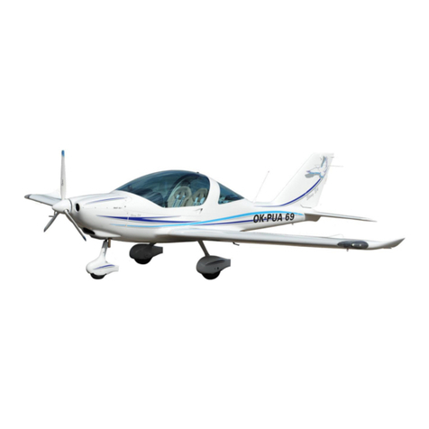
Wing span:2500 mm
Length: 1625 mm
Flying Weight: 2600g
Motor: double 2814 outrunner motor
ESC: double 50A hobby wing
Servo: 9g servo*5,17g servo*2
Prop: 10*7 *2
Biggest battery carrying capacity: 4S 50000mah battery
Heaviest safety take-off weight: 5500g
Default battery: 4S 10000mah

1.Before Assembling the Model
Please check the contents of your package before you start working on it.
You will find Fig. 1 + 2 and the Parts List helpful
here
Item
Material
Qty
1
Stickers
2
2
Connecting rod(11mm)used for connect the Mid wing and aileron wing
2
3
Middle stick
1
4
Connecting rod(5mm) used for connect the Mid wing and aileron wing
2
5
Connecting rod(25mm)used for connect the empennage and fuselage
1
6
Connecting rod(25mm) used for connect the empennage and fuselage
1
7
Spare parts include the push rods, screw and etc
1
8
Prop—10*7 CW and CCW
2
9
Fuselage
1
10
Horizontal and vertical
2
11
Mid wing
1
12
Aileron
2
13
¢5.8 fibreglass pine used for connect the Connecting rod(25mm)

2.Assembly guide
2-1)Assembly all the servo
Assembly the servo for Aileron as below
Assembly the servo for Horizontal and vertical as below
Assembly the servo for parachute cabin

2-2)Assembly the motor
Please install the motor as below
To make sure the motor direction as below
2-3)Assembly the ESC
Install the 2 pcs esc as below

glue the Mid wing cover board.
Notice: If you used for FPV flight, please put the extension wire of GPS and Tx first before
Glue it.
2-4)Assembly the vertical fin, horizontal and connecting rod
Assembly the vertical fin---glued the fixedblock and vertical .
Install the extension wire into the connecting rod and take notice of the direction.

Connect the vertical fin and horizontal with the connecting rod.
Push the connecting rod into the fuselage and take notice of the distance as below, After push it please raking-out
the extension wire from the right side of the connecting rod, then It can connect with the receiver.

2-5)Assembly the Mid wing with the fuselage
Glue the Mid wing and fuselage and then cover the Mid wing. Later Screw the PM3*60,and at the Bottom of
fuselage, you will use the M5 nuts to fix the connecting rod so it can’t roll.

2-6) Assembly the aileron with the fuselage
By the connecting rods you can connect the aileron with the fuselage, But at first you need glue the short pine into
the fiberglass tube, so the connecting rods can as a whole. Please take notice of the Distance .

2-7)Assembly the parachute cabin cover
Supplementary instruction
we design this plane for FPV flight, So we reserve a place for FPV equipment, If you want to take it as FPV flight
you can put some equipment before glue it, We suggest the position as below.

3.C.G adjust
C.G position
Please make sure the CG position at this.
4. Other instruction
LiPo charging instructions
Charge the LiPo battery by connecting the wall socket adapter (not included) to the balance charger.When
power is supplied to the balance charger, connect the charge lead (usually white) of the LiPo battery to the
balance charger.
Always supervise charger while in use and avoid charging battery for extended periods of time.
Power ON instructions
Make sure throttle stick and throttle trim is set to the “OFF”position and then power on the transmitter.
Afterwards power up the aircraft by connecting the battery to the electronic speed control. To power down,
power down in reverse order thus disconnect the battery to the electronic speed control then turn off the
transmitter.

Checking the power system
●Power on the transmitter with the throttle stick and trim at the “OFF”position then power up the aircraft.
Hold the aircraft securely.
Remove any loose objects such as cloths, tools, etc from the area in front of the model.
Open the throttle (stick forward): the motor should now run and you should feel a strong air flow rushing out
from propeller. Please do not bench test the unit for more than 10 seconds as there is no flowing air to cool
the unit.
Move the throttle stick back to the “OFF”position.
Disconnect the battery from the electronic speed controller and then switch the transmitter off.
Test flying –Notes on flying the airplane.
For the first flight you should wait for a relatively calm day with no more than a gentle breeze.
A good flying site is a large, flat, open field; well away from trees, fences, high-tension overhead cables and
other potentially dangerous obstacles.
Carry out a complete check of the working systems.
All control surfaces respond correctly
Adequate throttle response and battery voltage
Perform a range check if haven’t already
We recommend that you ask an experienced modeler to help you initially;
Switch the motor on, and launch the airplane strongly into the wind with the fuselage and wings leveled.
Allow the plane to fly straight and level initially; don’t try to turn it when it is close to the ground.
Adjust the trims if necessary so that the model settles into a steady climb.
Check the model’s response to control commands from the transmitter. You may need to increase or reduce
the control surface travels once the model is back on the ground.
Take the airplane up to a safe height and check its stalling speed.
Keep the speed well up on the landing approach to avoid stalling.
If you had to move the trims during the flight, correct the mechanical linkages before flying again. This allows
you to re-centre the trims, so that full trim travel is available for subsequent flights.
www.aeritech-uav.com
Table of contents


