ICON A5 Service manual

2141 ICON Way, Vacaville, CA 95688 ‐Tel: 707.564.4000 –www.iconaircraft.com
SERVICE LETTER
SL-042820 REV A
ICA009717-E PAGE 1 of 9
ID NUMBER & REVISION:
SL-042820-A
SUBJECT:
Seawing tip inspection and sealing
RELEASE DATE:
04/28/2020
EFFECTIVE DATE:
04/28/2020
SUPERSEDES NOTICE:
N/A
AIRCRAFT AFFECTED:
MAKE & MODEL:
ICON A5
SERIAL NUMBERS:
00075-00094 (inclusive)
ACTION:
None. Optional maintenance item
TIME OF COMPLIANCE:
Not Applicable. Recommend at next maintenance action
REVISION HISTORY:
A
Initial Release
LEVEL OF CERTIFICATION
REQUIRED (any level checked
can perform task):
☐
Pilot/Owner
☒
A & P
☒
LSA Repairman –Inspection
☐
Certified Repair Station
☒
LSA Repairman –Maintenance
☐
Manufacturer
PURPOSE:
ICON has become aware that the removable seawing tips on some A5 aircraft have departed the aircraft
during operational use as a result of hard landings on the water or while operating the aircraft beyond
the maximum suggested wave height of 12 inches. The departure of the seawing tip has created a large
gap or in some cases a hole on the outer seawing skin that has allowed water to intrude into the
Seawings™. The amount of water intrusion has overwhelmed the capacity of the bilge pump, leading to
significantly reduced buoyancy. ICON maintains that operations within the Water Operations Limitation
will preclude this type of damage. However, we also recognize that determining water conditions can be
difficult in real world scenarios and that unforeseen boat wakes and other surface waves can be hard to
predict.
Recognizing that operations in the above scenarios may occur unintentionally, ICON has updated the
bonding adhesive for the seawing tip mounting pins to a higher strength and begun to non-permanently
seal/bond the seawing tip to the Seawings™. Testing has shown these actions significantly reduce the
possibility of the seawing tip departing the aircraft during water operations, should there be inadvertent
use above the Water Operations Limitations. The Water Operating Limitations have not changed, since
the potential to damage the aircraft remains.
This engineering improvement is included on Aircraft Serial Number (ASN) 00075 and greater; however,
we have become aware that the work instructions may not have been performed correctly on ASN
00075-00094 (inclusive). This Service Letter includes instructions on how to perform the disassembly,
inspection, and proper re-installation of the sealed seawing tips. Although not mandatory, ICON Aircraft
will be completing this service letter on all internal fleet aircraft and highly recommends that owners of

2141 ICON Way, Vacaville, CA 95688 ‐Tel: 707.564.4000 –www.iconaircraft.com
SERVICE LETTER
SL-042820 REV A
ICA009717-E PAGE 2 of 9
affected serial numbers comply. This optional maintenance action is available under the ICON A5 limited
warranty, if applicable.
WARRANTY:
ICON Service Providers: Please submit an invoice for warranty reimbursement for labor and parts on
completion of this Service Letter. Reference service letter number SL-020520. Estimated labor hours:
1. 3-man hours of labor for disassembly, inspection, installation of hardware, and reassembly.
2. 2-man hours of labor for removal and replacement of all 8 seawing studs.
PARTS LIST:
PART
DESCRIPTION
QTY
KIT PART
NUMBER
Isopropyl Alcohol
TT-I-735A, or Equivalent
A/N
N/A
EA9394
Adhesive, Epoxy Paste, Hysol
1 Ea.
(50 mL cartridge)
ME001057-A
Kit, seawing tip
Sealing
SS-M4-RB23-4.75X13MM**
Stud, Non-Threaded W/Base, Cres, .1875x.500
8 Ea.
**ME001033 (ALT. PN)
Prepared Seawing Stud (Grit blasted base)
ICA013211
Wax, Carnauba
11 Oz.
(1 Container)
AC-251
Sealant, Aerospace, Black Class B, B-1/2
3 Ea.
(3.5 oz cartridge)
INSTRUCTIONS:
Remove seawing tip:
1. Remove the bolt securing the Seawing tip to the Seawing. Retain hardware for re-installation.
2. Remove the Seawing tip from the Seawing by applying pressure in the aft direction and rotating
up and away from the bottom Seawing skin. If necessary, use plastic soft scrapers to loosen
sealant.
3. Remove the sealant by peeling away from the Seawing skin or tip.
4. Clean Seawing tip and Seawing skin with isopropyl alcohol. Allow to dry completely prior to
proceeding with re-installation.
Inspect seawing tip studs:
1. Inspect 8 Ea (2 Ea forward and aft, LH and RH) Seawing Studs and Seawing Stud Bushings.
a. Remove and replace 8x Seawing Studs.
b. If Bushing is loose, coming disbonded or has uneven wear on tophat, remove and replace.
c. If there are cracks, voids, holes, or pockets in bonding, remove and replace.
Remove the affected component and re-bond in accordance with the following instructions.

2141 ICON Way, Vacaville, CA 95688 ‐Tel: 707.564.4000 –www.iconaircraft.com
SERVICE LETTER
SL-042820 REV A
ICA009717-E PAGE 3 of 9
Notes
1. Read repair instructions in their entirety before proceeding with this repair. Any questions
regarding interpretation of this disposition shall be forwarded to engineering immediately.
2. Unless otherwise specified, the following requirements apply when bonding features or
performing wet lay-up repairs:
2.1. No sprays, release agents, uncured silicone, or silicone-based lubricants shall be allowed
in the vicinity of the repair area.
2.2. Prior to application of adhesive, protect any areas that should not come in contact with
adhesive (fittings, hardware, exterior surfaces, etc.).
2.3. Unless otherwise specified, follow adhesive manufacturer's recommendations for material
handling, preparation, application, cleanup, and curing. Repair shall be completed (i.e.
bond closed, or wet lay-up repair placed under vacuum) within adhesive work life.
3. Composites are highly susceptible to impact and delamination damage. When breaking
bonds, be very careful not to damage the laminate of either substrate. Any damage will
require additional review by ICON Aircraft before proceeding with the repair.
4. During damage removal and tapered blend operations, be careful not to damage surrounding
structure, including adjacent parts, integral core, etc.
5. During any cutting or abrading process, ensure that the laminate is not over-heated; all
substrate materials must be protected from excessive temperatures (exceeding 200 °F).
6. When curing Hysol EA 9394 or EA 9396, use the following cure schedule:
6.1. Initial-cure the laminate or bond at 110-120 °F for 55-65 minutes.
6.2. Post-cure the laminate or bond at 190-200 °F for 55-65 minutes.
7. For bonded joints, Hysol EA 9394 paste adhesive shall be applied in a quantity sufficient to
meet bond gap requirements, such that the joint will be completely filled over the faying
surface with no areas void of adhesive. Excessive squeezout of adhesive shall be removed.
All edges of bond shall be filleted where possible.
8. For bonded joints, bondline thickness shall be 0.040 +/- 0.020 inch. Apply clamping pressure
as required to achieve the required bondline thickness. Clamping pressure shall not be
released until bond is at least initially cured. Do not apply, remove, and re-apply clamping
pressure, as this will cause air entrapment. If removal of a component is required, re-prepare
the joint in accordance with ICA010822.
Instructions
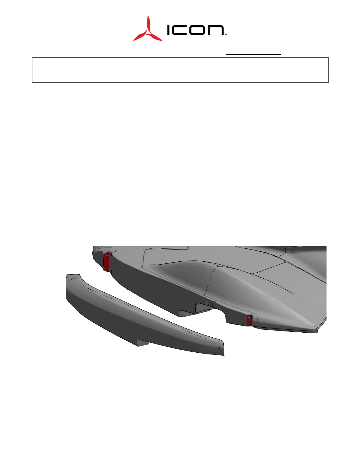
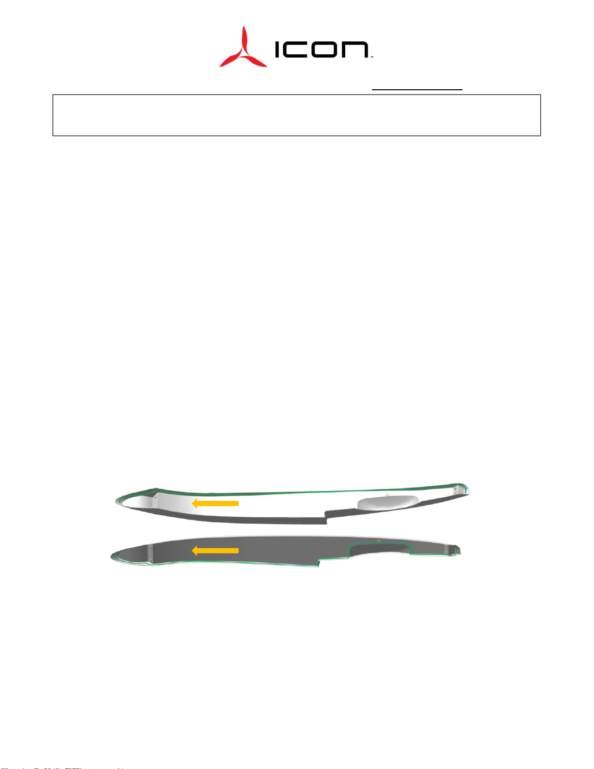
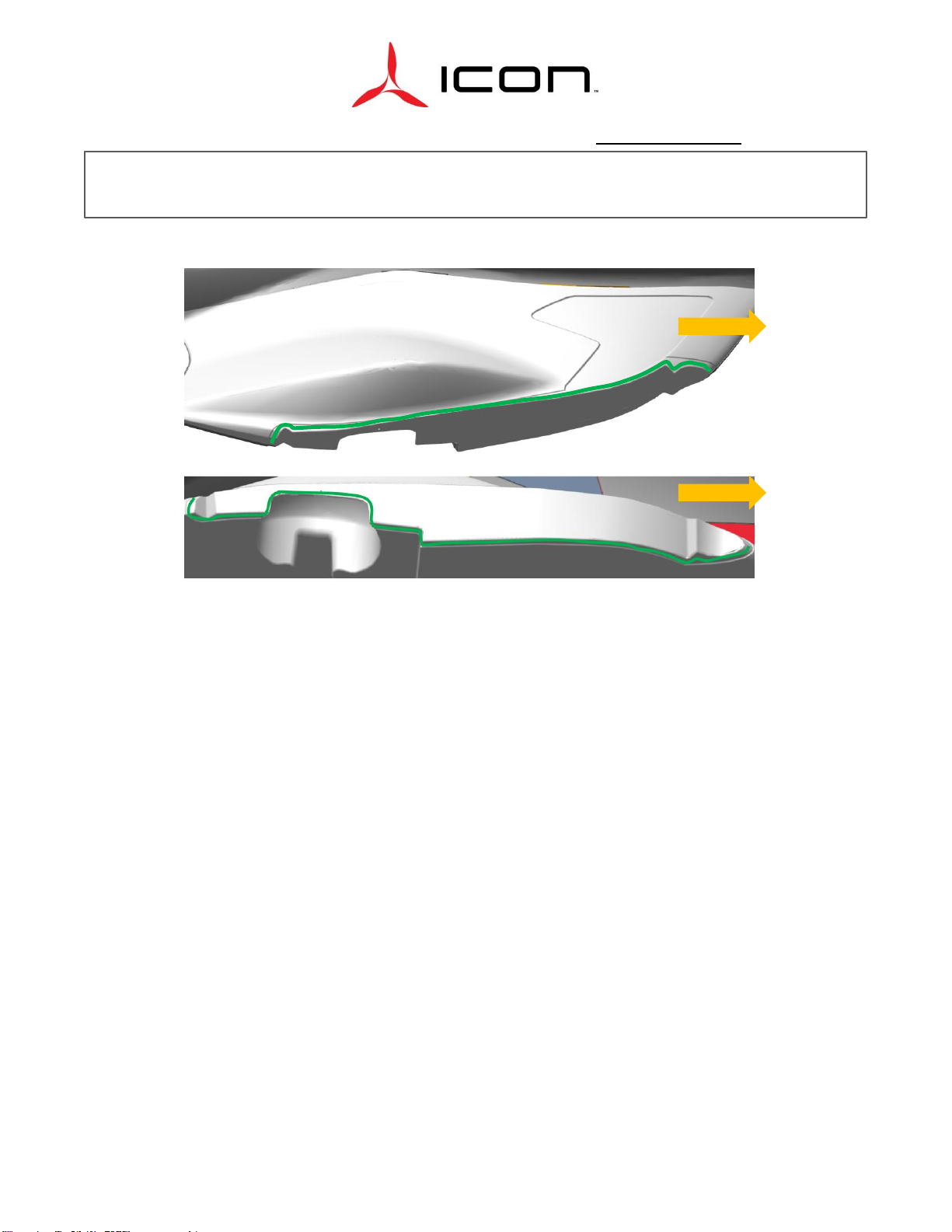
1. Carefully cut away the seawing studs and bushings as required. Studs may also be removed
by gently heating using a heat gun.
a. All substrate materials must be protected from excessive temperatures (exceeding 200
°F) during the application of heat to soften adhesive materials when breaking bonds.
Excessive temperatures can cause disbond, delamination, and blistering of composite

2141 ICON Way, Vacaville, CA 95688 ‐Tel: 707.564.4000 –www.iconaircraft.com
SERVICE LETTER
SL-042820 REV A
ICA009717-E PAGE 4 of 9
substrates, resulting in a loss of strength and reliability. Utilize the following methods to
prevent temperature damage
b. Keep the maximum output air temperature of the heat gun below the threshold of
damage temperature of the substrate and any surrounding components (i.e. 200 °F)
c. Use any available technologies to (infrared, temperature sensitive paint, etc.) monitor
the temperature of the nearby substrate during the operation. It should always be
below the threshold temperature (i.e. 200 °F)
d. Mask adjacent components and substrates with thermal barrier (silicone sheet or
aluminum foil mask) to minimize heat transfer to unintended areas.
2. Remove any remaining adhesive by sanding with aluminum oxide paper until the base
laminate is exposed. Do not damage the laminate.
3. Proceed with progressive inspection methods as required to ensure no damage has occurred
during the removal of the bond. Inspection methods may include visual, magnified visual,
borescope, tap testing, ultrasonic, etc. If required, carefully remove the surface protection by
abrasive methods. For paint, primer, and bodywork removal, sand surface with aluminum
oxide paper until the laminate is exposed. Do not damage the laminate.
4. Wipe areas marked in red below on Figure 1 the RH and LH Seawing (TM) with isopropyl
alcohol and a lint-free cloth. Allow 15 minutes to dry.
Figure 1 Bonding Area
5. Place 2 Ea .032” thick washers on the Seawing Studs and test fit Seawing tip for alignment
with the attachment bolt. Adjust washer thickness on each Stud until mounting bolt hole
aligns and there is a consistent reveal around the Seawing. These are used as temporary
shims.

2141 ICON Way, Vacaville, CA 95688 ‐Tel: 707.564.4000 –www.iconaircraft.com
SERVICE LETTER
SL-042820 REV A
ICA009717-E PAGE 5 of 9
6. In order to set the bond gap thickness, remove one .032” washer from each Stud. This will
ensure Studs/Bushings are receiving positive pressure while not over compressing during
installation.
7. Prepare Hysol 9394 IAW manufacturer instructions
**NOTE**
Once installed, allow to cure following manufacturer instructions. Do not attempt to
reposition or move as this may cause air pockets or voids in the bond.
8. Apply Hysol 9394 to Seawing Studs/Bushings as necessary (up to 8 Ea) place them in the
seawing tips and install the seawing tips to match bond them onto the abraded areas on the
RH and LH Seawing (TM).
9. Attach seawing tip to the fuselage using a bolt with 2 Ea washers into the existing nutplate.
Be careful not to over torque creating poor bond gap for Seawing Studs.
10. After allowing to cure, remove Seawing tip and follow instructions for Re-installation.
Re-install Seawing tip:
1. Apply carnauba paste wax onto the RH mating surfaces of the entire top and bottom interfaces
of the fuselage and Seawing tip. Allow 5 minutes for the wax to flash off. Wipe carnauba wax off
using a lint free cloth to leave thin film of residue on the mating surface. Repeat step a total of 3
times. Repeat process for LH side.
Figure 2 Carnauba Paste Wax Application to Seawing Tip

2141 ICON Way, Vacaville, CA 95688 ‐Tel: 707.564.4000 –www.iconaircraft.com
SERVICE LETTER
SL-042820 REV A
ICA009717-E PAGE 6 of 9
**NOTE**
Ensure that the work area is ready for the adhesive to be applied and that all tools,
consumables, PPE, etc. are quickly within reach. AC-251 B-1/2 adhesive has a minimum
application life of 30 minutes at 77°F with a relative humidity of 50%. The application life is
dependent on the temperature and humidity of the work environment
2. Mix AC-251 adhesive per manufacturer instructions:
a. Holding the cartridge, grasp the dasher rod and pull back approximately one inch
b. Insert the ramrod into the hollow of the dasher rod, break the piston loose, and inject
about 1/3 of the contents into the cartridge. Do not inject all of the catalyst in one
location. Distribute evenly throughout the base material
c. Repeat steps 1 and 2 until all the contents of the rod are emptied into the cartridge.
Remove the ramrod.
d. Mix for the required number of strokes (hand mix: 50-75 strokes) or for the required
amount of time (Machine mix: 37 strokes [1.5 minutes at 25 strokes/min])
e. When mixing is complete, remove bottom cap
f. Pull the dasher rod back to the neck of the cartridge, grasp the cartridge firmly at the
neck, unscrew the dasher rod and remove
g. Screw the nozzle into the cartridge, insert into the extrusion gun and use as required. For
hand extrusion, press the used dasher rod against the plunger to force the material from
the cartridge.
FWD
FWD
Figure 3 Carnauba Wax Application to Fuselage

2141 ICON Way, Vacaville, CA 95688 ‐Tel: 707.564.4000 –www.iconaircraft.com
SERVICE LETTER
SL-042820 REV A
ICA009717-E PAGE 7 of 9
**NOTE**
Mix the cartridges of AC-251 adhesive one by one as they are needed. Do not mix all the adhesive at
once.
3. Apply a 1/8” to 1/4” Diameter continuous bead of adhesive approximately centered along
indicated (highlighted in red) curve. Repeat process for LH side.
Figure 4 Sealant Application to Seawing
4. Place RH seawing tip onto 4x Studs (previously installed) on the fuselage. Repeat for LH Side.

2141 ICON Way, Vacaville, CA 95688 ‐Tel: 707.564.4000 –www.iconaircraft.com
SERVICE LETTER
SL-042820 REV A
ICA009717-E PAGE 9 of 9
6. Torque bolt to 26 in-lbs. Apply Torque Stripe.
7. Verify .060 +/- .020” gap reveal between seawing tip and seawing Joggle. Ensure Seawing
installation is complete.
Make the following logbook entry:
“The instructions of Service Letter (SL-042820-AA) have been complied with (ref. FAA Exemption
10829B)”.
If you have questions, comments, or concerns about this Service Letter and/or if you are no longer owner/operator
of this aircraft, please forward this information to the present owner/operator and notify ICON Aircraft at:
ICON Aircraft
2141 ICON Way
Vacaville, CA 95688
(855) FLY-ICON or (707) 564-4000
support@iconaircraft.com
Please include the aircraft registration number, serial number, your name, and if known the contact information of
the new owner/operator.
Other manuals for A5
2
This manual suits for next models
1
Table of contents
Other ICON Aircraft manuals
Popular Aircraft manuals by other brands

GRAVITY
GRAVITY X rocket manual

Ozone Power
Ozone Power FREERIDE 15 Pilot's manual

EVEKTOR-AEROTECHNIK
EVEKTOR-AEROTECHNIK EV-97? EUROSTAR ?model 2000 version R Pilot operating handbook

SOL paragliders
SOL paragliders Hercules 2 240 manual

Flex innovations
Flex innovations RV-8 instruction manual

Cessna
Cessna 182S Skylane Information manual