ICON STEREO TUBE POWER AMPLIFIER User manual

STEREO TUBE
POWER AMPLIFIER
STEREOTUBE
REAMPLIFIER
USER’S MANUAL
S.T.INNOVATORS - SOFIA 1505, 1, TZARICHINA STR., TEL. 870-21-56, FAX. 973-37-27

S.T.INNOVATORS
ICON rev.may 2010
2

S.T.INNOVATORS
ICON rev.may 2010
3
Table of Contents
IMPORTANT SAFETY INSTRUCTIONS!..............................................................................................4
1General Notes ..................................................................................................................................7
2Introduction ......................................................................................................................................7
3Performance Features .....................................................................................................................7
4ICON Stereo Tube Power Amplifier Dimensions .............................................................................8
5Installation of Tubes .........................................................................................................................9
•General Notes ...............................................................................................................................................9
•Power Output Tubes ...................................................................................................................................11
•Driver Tubes................................................................................................................................................12
•Indicator Tubes............................................................................................................................................12
•Small Input Tubes .......................................................................................................................................12
6Location and Ventilation.................................................................................................................13
7Tubes, Connections and Switches location ...................................................................................14
8How to Connect for Stereo.............................................................................................................16
9How to Operate the ICON ..............................................................................................................18
•Power On, Stand-by and Off .......................................................................................................................18
•Input Switch.................................................................................................................................................18
10 Setting the Tubes Bias...................................................................................................................19
11 Specifications.................................................................................................................................20
12 Packing Instructions.......................................................................................................................21
1General Information .......................................................................................................................23
2ICON Stereo Tube Preamplifier Features ......................................................................................23
3ICON Dimensions ..........................................................................................................................24
4Installation......................................................................................................................................25
5Front Panel Controls ......................................................................................................................25
6Rear Panels Connections ..............................................................................................................26
7How to Connect the ICON Preamplifier .........................................................................................27
8How to Operate the ICON Preamplifier..........................................................................................28
9Ventilation ......................................................................................................................................29
10 Specifications.................................................................................................................................30
11 Packing Instructions.......................................................................................................................31

S.T.INNOVATORS
ICON rev.may 2010
4
IMPORTANT SAFETY INSTRUCTIONS!
PLEASE READ THEM BEFORE OPERATING THIS EQUIPMENT.
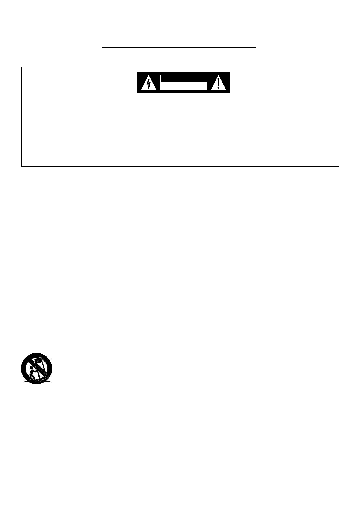
The lightning flash with arrowhead,
within an equilateral triangle, is intended
to alert the user to the presence of
uninsulated "dangerous voltage" within
the product's enclosure that may be of
sufficient magnitude to constitute a risk
of electric shock to persons.
CAUTION
RISK OF ELECTRIC SHOCK
DO NOT OPEN
A
VIS
RISQUE DE CHOC ELECTRIQUE - NE PAS OUVRIR.
The exclamation point within an equi-
lateral triangle is intended to alert the
user to the presence of important
operating and maintenance (servic-
ing) instructions in the literature ac-
companying the appliance.
WARNING - TO REDUCE RISK OF
FIRE OR ELECTRICAL SHOCK, DO
NOT EXPOSE THIS EQUIPMENT TO
RAIN OR MOISTURE.
NO USER-SERVICEABLE PARTS
INSIDE. REFER SERVICING TO
QUALIFIED PERSONNEL.
To prevent the risk of electric shock, do not remove cover
or back. No user serviceable parts inside.
General:
1. Read these instructions.
2. Keep these instructions.
3. Heed all warnings.
4. Follow all instructions.
5. Warning: To reduce risk of fire or electrical shock, do not expose this equipment to rain or moisture. This
unit is capable of producing high sound pressure levels. Continued exposure to high sound pressure levels
can cause permanent hearing impairment or loss. User caution is advised and ear protection is recommended
when playing at high volumes.
6. Caution: to prevent electrical shock do not use this (polarized) plug with an extension cord, receptacle or
other outlet unless the blades can be fully inserted to prevent blade exposure.
Attention: pour pevenir les chocs elecriques pas utiliser cette fiche polarisee avec un prolongateur, une prise
de courant ou un autre sortie de courant, sauf si les lames peuvent etre inserees afond ans en laisser aucune
partie a decouvert.
7. Unplug this equipment during lightning storms or when unused for long periods of time.
8. Only use attachments/accessories specified by the manufacturer.
Installation:
9. The equipment shall be installed near the AC Socket Outlet and the disconnect device shall be easily accessible.
10. Do not block any ventilation openings. Install in accordance with the manufacturer's instructions.
11. Do not install near any heat sources such as radiators, heat registers, stoves, or other equipment (including
amplifiers) that produce heat.
12. Do not use this equipment near water.
13. Do not expose this equipment to dripping or splashing and ensure that no objects filled with liquids, such as vases,
are placed on the equipment.
14. Use only with the cart, stand, tripod, bracket, or table specified by the manufacturer, or sold with the equipment.
When a cart is used, use caution when moving the cart/equipment combination to avoid injury from tip-over.
Connection:
15. Connect this equipment only to the type of AC power source as marked on the unit.
16. Protect the power cord from being walked on or pinched particularly at plugs, convenience receptacles, and the
point where they exit from the equipment.
17. Do not defeat the safety purpose of the polarized or grounding-type plug.
A polarized plug has two blades with one wider than the other. A grounding type plug has two blades and a third
grounding prong. The wide blade or the third prong are provided for your safety. If the provided plug does not fit into
your outlet, consult an electrician for replacement of the obsolete outlet.
18. Do not overload wall outlets, extension cords or integral convenience receptacles as this can result in a risk of fire
or electric shock.

S.T.INNOVATORS
ICON rev.may 2010
5
19. To completely disconnect this equipment from the AC Mains, disconnect the power supply cord plug from the AC
receptacle.
Care of Equipment:
20. Clean only with a dry cloth.
21. Do not permit objects or liquids of any kind to be pushed, spilled and/or fall into the equipment through enclosure
openings.
22. Unplug the power cord from the AC power outlet when left unused for a long period of time.
Repair of Equipment:
23. Refer all servicing to qualified service personnel. Servicing is required when the equipment has been damaged in
any way, such as power-supply cord or plug is damaged, liquid has been spilled or objects have fallen into the
equipment, the equipment has been exposed to rain or moisture, does not operate normally, or has been dropped.
24. Do not attempt to service beyond that described in the operating instructions. All other service should be referred
to qualified service personnel.
25. When replacement parts are required, be sure the service technician has used replacement parts specified by
S.T.Innovators or have the same characteristics as the original part. Unauthorized substitutions may result in fire,
electric shock, or other hazards.
26. Upon completion of any service or repairs to this product, ask the service technician to perform safety checks to
determine that the product is in proper operating condition.
Customer Service
If it is determined that your S.T.Innovators product is in need of repair, you can return it to your dealer. You can also
return it to the S.T.Innovators Service Department. For assistance on factory repair return procedure, contact the
S.T.Innovators Service Department at:
S.T.Innovators, Ltd.
1 Tzarichina, Str.
1505 Sofia, Bulgaria
Phone: +359 2 870 21 56
Fax: +359 2 973 37 27

S.T.INNOVATORS
ICON rev.may 2010
6
STEREO TUBE
POWER AMPLIFIER

S.T.INNOVATORS
ICON rev.may 2010
7
1 General Notes
1. Caution: To prevent electrical shock make sure that the AC POWER CORD IS NOT CONNECTED TO THE
ICON when inserting or removing Vacuum Tubes, as there are hazardous voltages present at the pins of the Tube
Sockets.
2. If the ICON has been ON, please allow the Hot Vacuum Tubes to cool first before removing them.
3. For additional connection information, refer to the owner's manual(s) for any component(s) connected to the
ICON.
4. It is very important that loudspeaker cables of adequate size be used, so that there will be minimum power
loss. The size is specified in Gauge Numbers or AWG, (American Wire Gauge).
The smaller the Gauge number, the larger the wire size.
Connection Terminals will accept up to a 8 AWG wire size:
If your loudspeaker cables are 50 feet (38.1m) or less, use at least 14 Gauge.
If your loudspeaker cables are 100 feet (76.2m) or less, use at least 12 Gauge.
5. Pin configuration for the XIR Balanced Input connectors on the ICON:
PIN 1: Shield or ground
PIN 2: + input
PIN 3: - input
2 Introduction
ICON is an HI-end stereo tube power amplifier with the silky-smooth sound and incredible detail that only a tube
amplifier can provide.
Two 100 watt high current output channels will drive any high quality loudspeaker system to its ultimate performance.
The ICON reproduction is sonically transparent and absolutely accurate.
3 Performance Features
•Power Output
The ICON consists of two separate power amplifier channels, each capable of 100 watts into 4 or 8 ohm loudspeakers
in stereo. It may also be operated in mono at 200 watts into 2 or 4 ohm loudspeakers.
•Balanced and Unbalanced Inputs
Balanced connections guard against induced noise and allow long cable runs without compromising sound quality.
Pin2
Pin1
Pin3

S.T.INNOVATORS
ICON rev.may 2010
8
4 ICON Stereo Tube Power Amplifier Dimensions
The following dimensions can assist in determining the best location for your ICON.
Front View of ICON
Figure 1
Rear View of ICON
Figure 2
Side View of ICON
Figure 3

S.T.INNOVATORS
ICON rev.may 2010
9
5 Installation of Tubes
Figure 4
•General Notes
Caution: To prevent electrical shock make sure that the AC POWER CORD IS NOT CONNECTED TO THE
ICON when inserting or removing Tubes, as there are hazardous voltages present at the pins of the Tube
sockets.
Your ICON has gone through an extensive series of performance tests during the manufacturing process. The ICON is
supplied with the actual Tubes that were used to test and confirm the performance of this amplifier. To protect the
Vacuum Tubes from possible shipping damage, they could be packed in layer of foam and placed into the Tube Box. It
is secured to the ICON Chassis.
If that is your case then follow the next steps:
Note: Gloves or a soft cloth will prevent "fingerprinting" of the Tubes during their installation.
1. Using an appropriate screwdriver, remove screw from the bottom of Power Switch Knob and pull it from the Front
Panel. Refer to figure 4.
2. Carefully pull out whole amplifier chsssis.
3. Orient the ICON’s chassis so the Front Side is facing you. Cut off the support strip from the Tube Box and
carefully lift up the Tube Box.
4. Orient the Tube Box so the “FRONT SIDE” is facing you. Using an appropriate screwdriver, remove four screws
from the cover and open the Tube Box. Refer to figure 5
5. Remove the first and second layer of foam to expose the Tubes.
6. Carefully remove the Tubes from the remaining pieces of foam and temporarily place them in a safe location.
ICON’s frame
Support
strip
ICON’s
chassis
Power Switch
knob
Tube Box

S.T.INNOVATORS
ICON rev.may 2010
10
Figure 5
Tube Box
GU50 (V5L)
GU50 (V4L)
GU50 (V4R)
GU50 (V5R)
GU19-1 (V3L)
6N1P-EV (V2L)
6N1P-VI (V1L)
EM800 (V6L)
EM800 (V6R)
6N1P-VI (V1R)
6N1P-EV (V2R)
GU19-1 (V3R)

S.T.INNOVATORS
ICON rev.may 2010
11
Figure 6
The ICON Chassis has nomenclature screened on it to specify both the circuit location and Tube type for each
channel. Refer to figure 6.
Note: It is extremely important to insert the Tubes in the correct location.
Note: Do not change the places of right and left channel tubes.
Note: It is extremely important removing of Tubes to become when they are fully cooled.
Note: Gloves or a soft cloth will prevent "fingerprinting" of the Tubes during their installation.
•Power Output Tubes
1. Orient the Chassis so that the Front Panel of the Amplifier is facing you.
1. Locate a GU50 (V5L) Power Output Tube. Refer to figure 6.
2. On the top left side of the amplifier, locate the Tube Socket that has the nomenclature V5L next to it on the chassis.
3. Orient the Tube so that the key on the base of the Tube is aligned with the corresponding key on the Tube Socket.
4. Carefully insert the Tube into the socket until the base of the Tube is fully seated in the Tube Socket.
5. Repeat the above the steps for the remaining 3 Power Output Tubes (V4L, V4R & V5R).
V4L
V5L
V6L
V1L
V2L
V3L
V4R
V5R
V6R
V1R
V2R
V3R

S.T.INNOVATORS
ICON rev.may 2010
12
Figure 7
•Driver Tubes
1. Locate a GU19-1 (V3L) Tube.
2. On the top left side of the amplifier, locate the Tube Socket that has the nomenclature V3L next to it on the
chassis. Refer to figure 6.
3. Orient the Tube so that the key on the base of the Tube is aligned with the corresponding key on the Tube Socket.
4. Carefully insert the Tube into the socket until the base of the Tube is fully seated in the Tube Socket.
5. Slip on two cylindrical terminals to the A1 – top lead and A2 – top lead of the tube. Refer to figure 7
6. Repeat the above steps for the remaining GU19-1 (V3R) Tube.
•Indicator Tubes
1. Locate an EM800 (V6L) Tube.
2. On the top left side of the amplifier, locate the Tube Socket that has the nomenclature V6L next to it on the
chassis. Refer to figure 6.
3. Orient the Tube so that the area where no pins are located on the base of the Tube is aligned with the
corresponding area on the Tube Socket.
4. Carefully insert the Tube into the socket until the base of the Tube is fully seated in the Tube Socket.
5. Repeat the above steps for the remaining EM800 (V6R) Tube.
•Small Input Tubes
There are two different types of Small Input Tubes (6N1P-EV and 6N1P-VI) used in each channel. Tube type can be
found on the outside of the Tube. The ICON will not function if they are inserted into the wrong socket.
1. Locate a 6N1P-EV (V2L) Tube.
2. On the top left side of the amplifier, locate the Tube Socket that has the nomenclature V2L next to it on the
chassis. Refer to figure 6.
3. Orient the Tube so that the area where no pins are located on the base of the Tube is aligned with the
corresponding area on the Tube Socket.
4. Carefully insert the Tube into the socket until the base of the Tube is fully seated in the Tube Socket.
5. Repeat the above steps for the remaining 6N1P-EV (V2R) Tube.
6. Locate a 6N1P-VI (V1L) Tube.
7. On the top left side of the amplifier, locate the Tube Socket that has the nomenclature V1L next to it on the chassis.
8. Insert the Tube, following the same procedures as in steps 3 and 4.
9. Repeat the steps 6-9 for the remaining 6N1P-VI (V1R) Tube.
After installation of all tubes follow the steps:
1. Orient the ICON so the Back Side is facing you. Carefully pull in whole chassis inside the ICON’s stainless steel
cover.
2. Orient the ICON so the Left Side is facing you. Using an appropriate screwdriver, screw on six screws to the
Left Side of ICON.
A1
A2
A2
A1

S.T.INNOVATORS
ICON rev.may 2010
13
3. Orient the ICON so the Right Side is facing you. Using an appropriate screwdriver, screw on six screws to the
Right Side of ICON.
4. Slip on the Power Switch Knob and using an appropriate screwdriver put in the screw into knob.
6 Location and Ventilation
The ICON can be placed upright on a table or shelf, standing on its four feet. Adequate ventilation extends the trouble
free life of the ICON. The suggested minimum space for operating the ICON is 70 cm in width, 60 cm in depth, and 60
cm in height. Always allow air to flow through the ventilation holes on the bottom of the amplifier and a means for the
warm air to escape at the top, refer to figure 8
Figure 8
Cool Air
Warm Air

S.T.INNOVATORS
ICON rev.may 2010
14
7 Tubes, Connections and Switches location
1
3
5
2
4
6
7911 8101213
Figure 9
1, 3 – GU50 – output tubes for left channel;
2, 4 – GU50 – output tubes for right channel;
5, 6 – GU19-1 – driver tubes;
7, 8 – 6N1P-EV – input tubes;
9, 10 – 6N1P-VI – input tubes;
11, 12 – EM800 – indicator tubes
13 – Power Switch (3-positions: OFF, STBY (standby) and ON).

S.T.INNOVATORS
ICON rev.may 2010
15
Figure 10
1, 2 – output transformers;
3, 4 – RIGHT and LEFT balanced inputs - for audio cables from a preamplifier or control center audio outputs;
5, 6 – RIGHT and LEFT unbalanced inputs (RCA) - for audio cables from a preamplifier or control center audio
outputs;
7 – Input switch selects between the BALANCED or UNBALANCED INPUTS;
8, 9 – RIGHT and LEFT outputs - connections for loudspeakers;
10 – grounding connector;
11 – power synchronization connector with preamplifier;
12 – Input 12V trigger for remote power control;
13 – Power supply connector - Connect the ICON power cord to a live AC outlet. Refer to information on the back
panel to determine the correct voltage;
14 – Fuses 6,3А- Main Fuse holder, refer to information on the back panel of your ICON to determine the correct
fuse size and rating.

S.T.INNOVATORS
ICON rev.may 2010
16
8 How to Connect for Stereo
Caution: The supplied AC Power Cord should not be connected to the Rear Panel of the ICON until after the
Loudspeaker Connections have been made. Failure to observe this could result in Electric Shock.
1. Connect cables from the Balanced Outputs of a preamplifier or control center to the ICON Left and Right
Balanced Inputs.
Note: An optional hookup is to use unbalanced cables.
2. Prepare the Loudspeaker Hookup Cables that attach to the ICON Power Amplifier Output Terminals by
choosing one of the methods below:
Bare wire cable ends:
Carefully remove sufficient insulation from the cable ends. If the cable is stranded, carefully twist the strands together
as tightly as possible.
Note: If desired, the twisted ends can be tinned with solder to keep the strands together, or attach spade lug and/or
banana connector.
Spade lug or prepared wire connection:
Insert the spade lug connector or prepared section of the cable end into the terminal side access hole, and tighten the
terminal cap until the cable is firmly clamped into the terminal so the wires cannot slip out.
Banana plug connection:
Insert the banana plug into the hole at the top of the terminal. Tighten the top portion of the terminal post to secure the
banana plug in place.
Note: The use of Banana Plugs is for use in the United States and Canada only.
3. Locate the Terminal Connection Cover and pass the Loudspeaker Hookup Cables thru the Loudspeaker Cable
Openings located near the top of the Terminal Cover.
4. Connect the Loudspeaker Hookup Cables to the output terminals that match the impedance of your loudspeakers,
being careful to observe the correct polarities. Output impedance connections of 4 ohm and 8 ohm are provided. If the
impedance of your loudspeakers is in-between the available connections, use the nearest lower impedance
connection.
WARNING: Loudspeaker terminals are hazardous live and present a risk of electric shock.
5. Rotate the ICON Power Switch on front panel to the OFF Position and connect the supplied power cord to an active AC
outlet.

S.T.INNOVATORS
ICON rev.may 2010
17
Connect to
AC Outlet
Connect to
AC Outlet
Figure 11 – Stereo Connection

S.T.INNOVATORS
ICON rev.may 2010
18
9 How to Operate the ICON
•Power On, Stand-by and Off
Rotate the POWER switch to the ON position and sound will be heard from the Loudspeakers when the tubes have
reached their operating temperature. The amount of time it takes is dependent upon the temperature of the Tubes
(about 3 min - smooth increment of heating voltage). Rotate the POWER Switch to the OFF position to stop amplifying
the audio signal. Refer to figure 12.
Standby Mode:
The ICON amplifier SHOULD NOT BE LEFT RUNNING WHEN NOT IN USE. Unlike solid state amplifiers, tube
amplifiers should be shut down when not being used.This will greatly prolong tube life. A standby mode has been
provided for short-term use between listening sessions so that the amp will remain in a “warmed up“ state. If you will
not be listening to the amplifier for more than an hour, it is advised that the amplifier be turned off. The standby switch
lowers the voltage on the tubes and heater filaments to ½ of normal operating voltage. Some output (distorted) will be
heard so the source material should be turned off when in standby mode.
OFF STBY ON
Figure 12
•Input Switch
When BALANCED Input Connections are used, place the ICON INPUT Switch to the BALANCED position (forward). If
UNBALANCED connections are used, place the INPUT Switch to the UNBALANCED position (backward). Refer to
figure 13.
Figure 13

S.T.INNOVATORS
ICON rev.may 2010
19
10 Setting the Tubes Bias
Figure 14
The output tubes and driver tubes (the big ones – V3, V4 and V5) need to be “biased’ with a grid voltage that controls
the flow of electrical current through the tube. Tube biasing on the ICON amplifier has been designed to be both
simple and effective. On some amplifiers biasing is done for two or more tubes simultaneously. With this method, the
total current flowing through the group of tubes may be correct, but the current flow through any individual tube may
vary significantly from the optimal value. With the ICON amplifier the bias is set individually for each tube so that the
correct operating point is assured. An added benefit to this approach is that, should a tube fail prematurely, the single
tube can be replaced without having to purchase a matched set. Use the following procedure to set the tube bias:
WARNING – There are dangerous and potentially lethal voltages inside this amplifier. Do not touch any part of
the amplifier other than as described below. If you are uncertain about any of these instructions, please
contact to S.T.Innovators and have them bias the amplifier for you.
1. Allow the amplifier to warm up for at least 30 minutes.
2. Turn the preamplifier off so that no signal is entering the amplifier
3. Carefully pull forward the front panel.
4. Locate the trimmer potentiometers labeled “BIAS CURENT”, “SYMMETRY” and “LEVEL”.
5. Using an appropriate screwdriver, slowly turn the screw on the potentiometer so that to turn off the
corresponding LED.
6. Repeat the above steps for each of the tubes in both channels.

S.T.INNOVATORS
ICON rev.may 2010
20
11 Specifications
Power Output Stereo
Maximum output power per each channel
100 W RMS 4 Ω/ 8 Ωload
Rated Frequency Band 20 Hz to 70 kHz
Frequency Response +0, +0.25 dB from 20Hz to 20,000Hz
+0, -3 dB from 15Hz to 70,000Hz
Total Harmonic Distortion
Maximum Total Harmonic Distortion at any power level
from 250 milliwatts to rated power
0.4% for 4 or 8 Ωload
Sensitivity 1 V unbalanced inputs
1 V balanced inputs
A-Weighted Signal To Noise Ratio 100 dB
Intermodulation Distortion
0.5% for 4 or 8 Ωload
Wide band Damping Factor
Greater than 8
Input Impedance
100 kΩunbalanced inputs
200 kΩbalanced inputs
Power Supply
Impulse power supply
120 V (from 100 to 135 V), 50/60 Hz at 10 А
230 V (from 195 to 260 V), 50/60 Hz at 5 А
Warm up time 3 minutes - smooth increment of heating voltage
Stand-by mode
Available
Circuit type PPP – push pull parallel scheme class AB
Vacuum Tubes
All tubes are military type
Input Tubes: 2 x 6N1P-EV and 2 x 6N1P-VI
Driver Tubes: 2 x GU19-1
Output Tubes: 4 x GU50
Indicator Tubes for output power: 2 x EM800
Control Precise electronic control of Bias mode of the tubes
with indication for symmetry and tubes current tuning
Overall Dimensions (H x W x D)
250 x 475 x 520 mm
(H x W x D) including feet and knob
282 x 475 x 547 mm
Weight 38.7 kg
Other manuals for STEREO TUBE POWER AMPLIFIER
1
This manual suits for next models
2
Table of contents
Other ICON Amplifier manuals
Popular Amplifier manuals by other brands

Extron electronics
Extron electronics P/2 DA2 EC F Specification sheet

Extron electronics
Extron electronics VGA Distribution Amplifiers P/2 DA4xi s Setup guide

Seeburg
Seeburg S Series Hardware manual

Astin Trew
Astin Trew AT2000 Operation manual

Altimium
Altimium AMP2B user manual

Yamaha
Yamaha AS1000BL Service manual