manuals.online logo
Brands
  1. Home
  2. •
  3. Brands
  4. •
  5. IDEAL
  6. •
  7. Boiler
  8. •
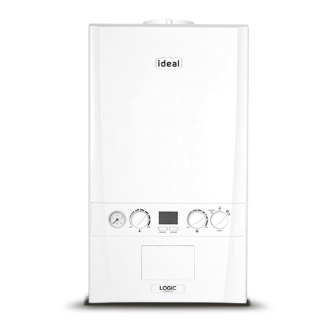
  9. IDEAL Elise H24 User manual

IDEAL Elise H24 User manual

This manual suits for next models

1

Other IDEAL Boiler manuals

IDEAL LOGIC CODE COMBI ESP1 33 User manual

IDEAL

IDEAL LOGIC CODE COMBI ESP1 33 User manual

IDEAL Concord ESi 140 User manual

IDEAL

IDEAL Concord ESi 140 User manual

IDEAL Viscount GTE 14 Guide

IDEAL

IDEAL Viscount GTE 14 Guide

IDEAL Mexico Super CF 3/60P User manual

IDEAL

IDEAL Mexico Super CF 3/60P User manual

IDEAL British Gas 100 RD2 Datasheet

IDEAL

IDEAL British Gas 100 RD2 Datasheet

IDEAL VOGUE MAX COMBI 26 User manual

IDEAL

IDEAL VOGUE MAX COMBI 26 User manual

IDEAL Project Heat 15 User manual

IDEAL

IDEAL Project Heat 15 User manual

IDEAL icos m3080 User manual

IDEAL

IDEAL icos m3080 User manual

IDEAL he15 User manual

IDEAL

IDEAL he15 User manual

IDEAL Vogue S15 User manual

IDEAL

IDEAL Vogue S15 User manual

IDEAL Independent + Combi C24 User manual

IDEAL

IDEAL Independent + Combi C24 User manual

IDEAL imax plus F80 User manual

IDEAL

IDEAL imax plus F80 User manual

IDEAL Concord CX40 Supplement

IDEAL

IDEAL Concord CX40 Supplement

IDEAL Vanguard L 170 User manual

IDEAL

IDEAL Vanguard L 170 User manual

IDEAL Optia FF 30 Release note

IDEAL

IDEAL Optia FF 30 Release note

IDEAL GTE 5 User manual

IDEAL

IDEAL GTE 5 User manual

IDEAL Concord ES140H User manual

IDEAL

IDEAL Concord ES140H User manual

IDEAL Vogue S15 User manual

IDEAL

IDEAL Vogue S15 User manual

IDEAL he15 User manual

IDEAL

IDEAL he15 User manual

IDEAL COMBI ESP 30 User manual

IDEAL

IDEAL COMBI ESP 30 User manual

IDEAL Classic LX RS 230 Release note

IDEAL

IDEAL Classic LX RS 230 Release note

IDEAL Response FF80 User manual

IDEAL

IDEAL Response FF80 User manual

IDEAL HE 260 User manual

IDEAL

IDEAL HE 260 User manual

IDEAL Vogue Combi c26 User manual

IDEAL

IDEAL Vogue Combi c26 User manual

Popular Boiler manuals by other brands

UTICA BOILERS BC3D Installation, operation & maintenance manual

UTICA BOILERS

UTICA BOILERS BC3D Installation, operation & maintenance manual

Lochinvar SOLUTION 260000 Installation & service manual

Lochinvar

Lochinvar SOLUTION 260000 Installation & service manual

Weil-McLain EG 6 Series manual

Weil-McLain

Weil-McLain EG 6 Series manual

RBI LCD Series Installation & operation manual

RBI

RBI LCD Series Installation & operation manual

Baxi MainEco Combi 28 Installation and service manual

Baxi

Baxi MainEco Combi 28 Installation and service manual

Unical ALKON R 24 Installation and Servicing Manual

Unical

Unical ALKON R 24 Installation and Servicing Manual

Automatic Heating Gasogen Installation and Servicing Manual

Automatic Heating

Automatic Heating Gasogen Installation and Servicing Manual

Viessmann VITORADIAL 300-T Type VR3 Service instructions for contractors

Viessmann

Viessmann VITORADIAL 300-T Type VR3 Service instructions for contractors

Alpha GasSaver GS-1 Installation and servicing instructions

Alpha

Alpha GasSaver GS-1 Installation and servicing instructions

Baxi ROCA LAURA PLUS 28/28 Operating, cleaning and maintenance instructions for the user

Baxi

Baxi ROCA LAURA PLUS 28/28 Operating, cleaning and maintenance instructions for the user

Vaillant uniSTOR VIH SW GB 500 BES operating instructions

Vaillant

Vaillant uniSTOR VIH SW GB 500 BES operating instructions

Kärcher HWE 4000 Gas manual

Kärcher

Kärcher HWE 4000 Gas manual

Radijator BIO max 23.1 instruction manual

Radijator

Radijator BIO max 23.1 instruction manual

Granby BKC Installation, operation and maintenance manual

Granby

Granby BKC Installation, operation and maintenance manual

Brunner BSV 20 Instructions for use

Brunner

Brunner BSV 20 Instructions for use

Potterton 50e Installation and Servicing Manual

Potterton

Potterton 50e Installation and Servicing Manual

UTICA BOILERS TriFire Assembly instructions

UTICA BOILERS

UTICA BOILERS TriFire Assembly instructions

ECR International UB90-125 Installation, operation & maintenance manual

ECR International

ECR International UB90-125 Installation, operation & maintenance manual

manuals.online logo
manuals.online logoBrands
  • About & Mission
  • Contact us
  • Privacy Policy
  • Terms and Conditions

Copyright 2025 Manuals.Online. All Rights Reserved.

installation and
servicing
Elise
(V3 Flue System)
Your Ideal installation and servicing guide
For details of document amendments, refer to page 3
When replacing any part on this appliance, use only spare parts that you can be
assured conform to the safety and performance specification that we require. Do not
use reconditioned or copy parts that have not been clearly authorised by Ideal Boilers.
H15, H24
For users guide see reverse of book
For the very latest copy of literature for specification purposes please visit our website
www.idealboilers.com where you will be able to download the relevant information in pdf format.
October 2007 UIN 203949 A01
2Elise - Installation & Servicing
3
Elise - Installation & Servicing
DOCUMENT AMENDMENTS
Relevant Installation changes implemented in this book from Mod Level ................................... A01 (Sept 07)
Ideal Stelrad Group reserve the right to vary specification without notice
4Elise - Installation & Servicing
GENERAL
Boiler Size H15 Max H24 Max Min
Boiler input 'Q' = Nett CV kW 15.1 24.4 9.1
Btu/h 51 500 83 300 31 000
Gross CV kW 16.8 27.1 10.1
Btu/h 57 200 92 500 34 400
Gas consumption l/s (cu.ft/h) 0.43 (54.7) 0.70 (89.7) 0.26 (33.3)
Boiler output 'P' = 70 oC Mean water kW 14.6 23.4 8.8
temperature Btu/h 50 000 80,000 30,000
40 oC Mean water kW 15.5 25.1 9.6
temperature Btu/h 53 000 85 700 32 800
Seasonal efficiency (SEDBUK) * Band A [90.4]% [90.2]%
NOx classification Class 5
Boiler Size H15, H24
Gas supply type and connection 2H-G20-20 mbar Rc1/2(1/2" BSP Female)
Injector size Stereomatic 5.6mm dia.
Flow connection 22mm copper
Return connection 22mm copper
Flue terminal diameter mm (in.) 100 (4)
Maximum static water head m (ft.) 30.5 (100)
Minimum static water head m (ft.) 0.45 (1.5)
Electrical supply 230 V ~ 50 Hz
Boiler power consumption 38W
Fuse rating External: 3A Internal: T3.15A L250 V
Water content litre (gal.) 1.7 (0.37)
Packaged weight kg (lb.) 38 (84)
Maximum installation weight kg (lb.) 31 (68)
Boiler size Height mm (in.) 582 (23)
Width mm (in.) 390 (15)
Depth mm (in.) 278 (11)
*The value is used in the UK Government's Standard Assessment Procedure (SAP) for energy rating of dwellings.
The test data from which it has been calculated have been certified by a notified body.
CAUTION.
To avoid the possibility of injury during the installation, servicing or cleaning
of this appliance, care should be taken when handling edges of sheet steel components.
Note.
Gas consumption is calculated using a calorific value of
38.7 MJ/m3(1038 Btu/ft3) gross or 34.9 MJ/m3 (935 Btu/ft3)
nett. To obtain the gas consumption at a different calorific
value:-
a. For l/s - divide the gross heat input (kW) by the gross
C.V. of the gas (MJ/m3)
b. For ft3/h - divide the gross heat input (Btu/h) by the
gross C.V. of the gas (Btu/ft3)
Key to symbols
GB = United Kingdom IE = Ireland (Countries of destination)
PMS = Maximum operating pressure of water
C13 C33 C53 = A room sealed appliance designed for connection via
ducts to a horizontal or vertical terminal which admits
fresh air to the burner and discharges the products of
combustion to the outside through orifices which, in this
case, are concentric. The fan is up stream of the
combustion chamber.
I2H = An appliance designed for use on 2nd Family gas, Group
H only.
Table 2 - Performance Data
Table 1 - Boiler Data
5
Elise - Installation & Servicing
GENERAL
CONTENTS
Air Supply ....................................................................... 9
Benchmark Commissioning Checklist ..................... 54
Boiler Clearances ......................................................... 6
Boiler Exploded Diagram ............................................ 14
Electrical Connections ............................................... 27
Electrical Supply ........................................................... 9
Electrical Systems Diagrams .................................... 30
Extension Ducts - Fitting ............................................. 19
Fault Finding ................................................................. 45
Flow Wiring Diagram .................................................. 29
Flue Fitting .............................................................. 16-19
Flue Installation Requirements .................................... 8
Gas Safety Regulations ................................................ 7
Gas Supply ..................................................................... 8
Initial Lighting .............................................................. 31
Installation ............................................................. 14-32
Mandatory Requirements ............................................. 7
Safe Handling ................................................................ 8
Servicing ................................................................ 33-44
Short List of Parts ....................................................... 49
Terminal Guards ............................................................ 8
Thermostatic Radiator valves .................................... 9
Water and Systems ................................................ 9-13
Water Connections ................................................. 6, 27
Water Treatment ......................................................... 13
Wiring Diagrams ......................................................... 29
Elise
Destination Countries: GB, IE
Boiler Page
Make and model ....................................................... 5
Appliance serial no. on data badge ...................... 14
SEDBUK No. % ......................................................... 4
Controls
Time and temperature control to heating ............. 30
Time and temperature control to hot water .......... 30
Heating zone valves .............................................. n/a
TRV's .........................................................................9
Auto bypass .............................................................. 9
Boiler interlock .......................................................... 9
For all boilers
Flushing to BS.7593 .............................................. 13
Inhibitor .................................................................. 13
Central heating mode
Heat input ................................................ to be calculated
For assistance see Technical Helpline on the back page
Page
Burner operating pressure .................................... n/a
Central heating flow temp. ...... measure and record
Central heating return temp. ... measure and record
For combination boilers only
Scale reducer ......................................................... n/a
Hot water mode
Heat input ...............................................................n/a
Max. operating burner pressure .............................. n/a
Max. operating water pressure ............................. n/a
Cold water inlet temp ............................................ n/a
Hot water outlet temp. ........................................... n/a
Water flow rate at max. setting .............................. n/a
For condensing boilers only
Condensate drain .................................................. 20
For all boilers: complete, sign & hand over to customer
For GB, to comply with Building Regulations Part L1 (Part 6 in Scotland) the boiler should be fitted in accordance with the
manufacturer's instructions. Self-certification that the boiler has been installed to comply with Building Regulations can be
demonstrated by completing and signing the Benchmark Commissioning Checklist.
Boiler size G.C. Appliance No. PI No.
Benchmark No.
H15 41 399 97 0063 BS 3016
H24 41 399 98 0063 BS 3016
Natural Gas only
BENCHMARK COMMISSIONING CHECKLIST DETAILS
NOTE TO THE INSTALLER:
COMPLETE
THE BENCHMARK COMMISSIONING
CHECKLIST AND LEAVE THESE
INSTRUCTIONS WITH APPLIANCE
6Elise - Installation & Servicing
GENERAL
nm8956
The boiler flow and return pipes are supplied fitted to the boiler
ready for top connection
Notes.
a. For the heating loads in excess of 60,000 Btu/h, 28mm (1") flow
and return pipes should be used to and from the boiler.
b. This appliance is NOT suitable for use with a direct hot water
cylinder.
1
BOILER WATER CONNECTIONS
A
nm8955
2
BOILER CLEARANCES all dimensions in mm (in.)
The following minimum clearances must be maintained for
operation and servicing.
Additional space will be required for installation, depending upon
site conditions.
Side and Rear Flue
aProvided that the flue hole is cut accurately, e.g. with a core drill,
the flue can be installed from inside the building where wall
thicknesses do not exceed 600mm (24"). Where the space into
which the boiler is going to be installed is less than the length of
flue required the flue must be fitted from the outside.
Installation from inside ONLY
b. If a core boring tool is to be used inside the building the space in
which the boiler is to be installed must be at least wide enough
to accommodate the tool.
Front clearance
The minimum front clearance when built in to a cupboard is
5mm (1/4") from the cupboard door but 450mm (17 3/4")
overall clearance is still required, with the cupboard door
open, to allow for servicing.
N.B. The boiler will not fit into a standard depth wall unit. In
order for it to do so the plastic fascia should be removed. See
Frame 41.
*Bottom clearance
after installation can be reduced to 5mm in an adequately
ventilated enclosed cupboard. However, 100mm must be
available for servicing.
nm8957
SIDE FLUE ONLY
Horizontal length of flue Top clearance
from centre line of boiler required (MIN.)
to outside wall Dim. A
0.5 m 165 mm (6 1/2")
1.0 m 170 mm (6 11/16)
1.5 m 185 mm (7 1/4")
2.0 m 200 mm ( 7 7/8")
2.5 m 210 mm (8 1/4")
3.0 m 225 mm (8 7/8")
3.5 m 235 mm (9 1/4")
4.0 m 250 mm (10 7/8")
4.5 m 260 mm (10 1/4")
5.0 m 275 mm (10 13/16")
5.5 m 290 mm (11 3/8")
6.0 m 300 mm (11 13/16")
REAR FLUE ONLY
MIN. Top clearance required = 145 mm (5 3/4")
7
Elise - Installation & Servicing
GENERAL
INTRODUCTION
The Elise range of boilers are a fully automatically controlled,
wall mounted, low water content, balanced flue, fanned,
condensing gas boiler. It has full modulating central heating
outputs of :
H15 8.8 kW (30,000 Btu/h) to 14.6 kW (50,000 Btu/h).
H24 8.8 kW (30,000 Btu/h) to 23.4 kW (80,000 Btu/h).
Due to the high efficiency of the boiler a plume of water vapour
will form at the flue terminal during operation depending on
external conditions.
The boiler casing is of white painted mild steel with the user
controls capable of being mounted remotely from the boiler, if
the option is required.
The heat exchanger is of cast aluminium.
Note.
These boilers cannot be used on systems which include gravity
circulation.
The boilers are suitable for connection to fully pumped, open
vented or sealed water systems. Adequate arrangements for
completely draining the system by provision of drain cocks
MUST be provided in the installation pipework.
OPERATION
When there is a demand for heat, the heating system is
supplied at the selected temperature of between 30oC and
82oC.
The boiler features a comprehensive diagnostic system which
gives detailed information on the boiler status when operating,
and performance of key components to aid commissioning and
fault finding.
SAFE HANDLING
This boiler may require 2 or more operatives to move it to its
installation site, remove it from its packaging base and during
movement into its installation location. Manoeuvring the boiler
may include the use of a sack truck and involve lifting, pushing
and pulling.
Caution should be exercised during these operations.
Operatives should be knowledgeable in handling techniques
when performing these tasks and the following precautions
should be considered:
• Grip the boiler at the base.
• Be physically capable.
• Use PPE as appropriate, e.g. gloves, safety footwear.
During all manoeuvres and handling actions, every attempt
should be made to ensure the following unless unavoidable
and/or the weight is light.
• Keep back straight.
• Avoid twisting at the waist.
• Avoid upper body/top heavy bending.
• Always grip with the palm of the hand.
• Use designated hand holds.
• Keep load as close to the body as possible.
• Always use assistance if required.
OPTIONAL EXTRA KITS
zFlue Extension Ducts (1000mm long up to 6m)
zFlue Finishing Kit
z90o Elbow Kit (maximum 4 elbows per installation).
z45o Elbow Kit (maximum 4 elbows per installation).
zRoof Flue Kit (to a maximum of 7.5m)
zPowered Vertical Flue Kit 5 m primary and 17m secondary
is a typical maximum flue length. For further details refer to
Powered Vertical Fluing Instructions.
zHigh Level Flue Outlet Kits
zFlue Deflector Kit
zWeather Collar
zTwin Fluing Kits (to a maximum of 60m combined total of
flue and air ducts)
zHorizontal Flue 600mm long
zRemote User Control Kit
zBoiler Stand-off Kit
zSiphon Kit
zCondensate Pump Kit
SAFETY
Current Gas Safety (Installation and Use) Regulations or
rules in force.
The appliance is suitable only for installation in GB and IE and
should be installed in accordance with the rules in force.
In GB, the installation must be carried out by a CORGI
Registered Installer. It must be carried out in accordance with
the relevant requirements of the:
• Gas Safety (Installation and Use) Regulations
• The appropriate Building Regulations either The Building
Regulations, The Building Regulations (Scotland), Building
Regulations (northern Ireland).
• The Water Fittings Regulations or Water byelaws in
Scotland.
• The Current I.E.E. Wiring Regulations.
Where no specific instructions are given, reference should be
made to the relevant British Standard Code of Practice.
In IE, the installation must be carried out by a Competent
Person and installed in accordance with the current edition of
I.S.813 "Domestic Gas Installations", the current Building
Regulations and reference should be made to the current ETCI
rules for electrical installation.
Detailed recommendations are contained in the following British
Standard Codes of Practice:
BS. 5440:1 Flues (for gas appliances of rated input not
exceeding 70 kW).
BS. 5440:2 Ventilation (for gas appliances of rated input not
exceeding 70 kW).
BS. 5449 Forced circulation hot water systems.
BS. 5546 Installation of gas hot water supplies for
domestic purposes (2nd Family Gases).
BS. 6798 Installation of gas fired hot water boilers of rated
input not exceeding 60 kW.
BS. 6891 Low pressure installation pipes.
Health & Safety Document No. 635
The Electricity at Work Regulations, 1989.
The manufacturer’s notes must NOT be taken, in any way, as
overriding statutory obligations.
IMPORTANT. These appliances are CE certificated for safety
and performance. It is, therefore, important that no external
control devices, e.g. flue dampers, economisers etc., are
directly connected to these appliances unless covered by these
Installation and Servicing Instructions or as otherwise
recommended by Ideal Stelrad Group in writing. If in doubt
please enquire.
Any direct connection of a control device not approved by Ideal
Stelrad Group may invalidate the certification and the normal
appliance warranty. It could also infringe the Gas Safety
Regulations and the above regulations.
8Elise - Installation & Servicing
GENERAL
SAFE HANDLING OF SUBSTANCES
Care should be taken when handling the boiler insulation
panels, which can cause irritation to the skin. No asbestos,
mercury or CFCs are included in any part of the boiler or its
manufacture.
LOCATION OF BOILER
The boiler must be installed on a flat and vertical wall, capable
of adequately supporting the weight of the boiler and any
ancillary equipment.
The boiler may be fitted on a combustible wall and insulation
between the wall and the boiler is not necessary, unless
required by the local authority.
For electrical safety reasons there must be no access from the
back of the boiler.
The boiler must not be fitted outside.
Timber Framed Buildings
If the boiler is to be fitted in a timber framed building it should
be fitted in accordance with the Institute of Gas Engineering
document IGE/UP/7:1998.
Bathroom Installations
This appliance is rated IP20.
The boiler may be installed in any room or internal space,
although particular attention is drawn to the requirements of the
current IEE (BS.7671) Wiring Regulations and, in Scotland, the
electrical provisions of the building regulations applicable in
Scotland, with respect to the installation of the boiler in a room
or internal space containing a bath or shower. For Ireland
reference should be made to the current ETCI rules for
electrical installations and I.S.813:2002.
If the appliance is to be installed in a room containing a bath or
shower then, providing water jets are not going to be used for
cleaning purposes (as in communal baths/showers), the
appliance can be installed in Zone 3, as detailed in BS.7671.
Compartment Installations
A compartment used to enclose the boiler should be designed
and constructed specially for this purpose.
An existing cupboard or compartment may be used, provided
that it is modified for the purpose.
In both cases details of essential features of cupboard /
compartment design, including airing cupboard installation,
are to conform to the following:
zBS. 6798. (No cupboard ventilation is required - see “Air
Supply” for details).
zThe position selected for installation MUST allow adequate
space for servicing in front of the boiler.
zFor the minimum clearances required for safety and
subsequent service see the wall mounting template and
Frame 2. In addition, sufficient space may be required to
allow lifting access to the wall mounting plate.
GAS SUPPLY
The local gas supplier should be consulted, at the installation
planning stage, in order to establish the availability of an
adequate supply of gas. An existing service pipe must NOT be
used without prior consultation with the local gas supplier.
The boiler MUST be installed on a gas supply with a governed
meter only.
A gas meter can only be connected by the local gas supplier or
by a CORGI registered engineer. In IE by a Competent Person.
An existing meter should be checked, preferably by the gas
supplier, to ensure that the meter is adequate to deal with the
rate of gas supply required.
N.B. The principle of the 1:1 gas valve ensures that the Elise
range is able to deliver it’s full output at inlet pressures down to
14mb. However if dynamic pressures below 20mb are
experienced ensure this is adequate for ALL other gas
appliances in the property.
IMPORTANT.
Installation pipes MUST be fitted in accordance with BS. 6891.
In IE refer to I.S.813:2002. Pipework from the meter to the boiler
MUST be of an adequate size, i.e. no longer than 20m and not
less than 15mm O.D.
The complete installation MUST be tested for gas soundness
and purged as described in the above code.
FLUE INSTALLATION
Pluming will occur at the terminal so terminal positions which
would cause a nuisance should be avoided.
The flue must be installed in accordance with the
recommendations of BS.5440-1:2000. In IE refer to I.S.813:2002.
The following notes are intended for general guidance.
1. The boiler MUST be installed so that the terminal is exposed
to external air.
2. It is important that the position of the terminal allows the free
passage of air across it at all times.
3. Minimum acceptable spacing from the terminal to
obstructions and ventilation openings are specified in Table 3.
4. Where the lowest part of the terminal is fitted less than 2m
(6'6") above a balcony, above ground or above a flat roof to
which people have access, then the terminal MUST be
protected by a purpose designed guard.
Ensure that the guard is fitted centrally.
Terminal guards are available from boiler suppliers. Ask for
TFC Flue Guard Model No. K6 (round plastic-coated). In
case of difficulty contact:
Grasslin (UK) Ltd. Tel. +44(0) 01732 359 888
Tower House, Vale Rise Fax. +44(0) 01732 354 445
Tonbridge. kent TN9 1TB www.ffc.ukco.com
5. The flue assembly shall be so placed or shielded as to
prevent ignition or damage to any part of any building.
Flue Terminal Positions
Min. Spacing*
1. Directly below, above or alongside an opening
window, air vent or other ventilation opening. 300mm (12")
2. Below guttering, drain pipes or soil pipes. 25mm ( 1")*
BS5440-1 2000 75mm (3")
3. Below eaves. 25mm (1")*
BS5440-1 2000 200mm (8")
4. Below balconies or a car port roof. 25mm (1")*
BS5440-1 2000 200mm (8")
5. From vertical drain pipes or soil pipes. 25mm (1")*
BS5440-1 2000 150mm (6")
6. From an internal or external corner or to a 25mm (1")*
boundary along side the terminal. BS5440-1 2000 300mm (12")
7. Above adjacent ground, roof or balcony level. 300mm (12")
8. From a surface or a boundary facing the terminal. 600mm (24")
9. From a terminal facing a terminal. 1,200mm (48")
10. From an opening in a car port
(e.g. door or window) into dwelling. 1,200mm (48")
11. Vertically from a terminal on the same wall. 1,500mm (60")
12. Horizontally from a terminal on the wall. 300mm (12")
Vertical Terminals
13. Above the roof pitch with roof slope of all angles. 300mm (12")
Above flat roof. 300mm (12")
14. From a single wall face. 600mm (24")
From corner walls. 1000mm (40")
Table 3 - Balanced Flue Terminal Position
* Only one reduction down to 25mm is allowable per installation
otherwise BS5440-1 2000 dimensions must be followed.
9
Elise - Installation & Servicing
GENERAL
Single feed, indirect cylinders are not recommended and MUST
NOT be used on sealed systems.
The appliances are NOT suitable for gravity central heating nor
are they suitable for the provision of gravity domestic hot water.
The hot water cylinder and ancillary pipework, not forming part
of the useful heating surface, should be lagged to prevent heat
loss and any possible freezing - particularly where pipes run
through roof spaces and ventilated underfloor spaces.
The boiler must be vented.
The hydraulic resistance of the boilers, at MAXIMUM OUTPUT,
with an 11 oC (20 oF) temperature differential, is shown in
Graph 1.
BOILER CONTROL INTERLOCKS
Ideal Stelrad Group recommend that heating systems utilising
full thermostatic radiator valve control of temperature in
individual rooms should also be fitted with a room thermostat
controlling the temperature in a space served by radiators not
fitted with such a valve as stated in BS. 5449.
Central heating systems controls should be installed to ensure
the boiler is switched off when there is no demand for heating
or hot water.
When thermostatic radiator valves are used, the space heating
temperature control over a living / dining area or hallway having
a heating requirement of at least 10% of the boiler heat output
should be achieved using a room thermostat, whilst other
rooms are individually controlled by thermostatic radiator
valves. However, if the system employs thermostatic radiator
valves on all radiators, or two port valves without end switches,
then a bypass circuit must be fitted with an automatic bypass
valve to ensure a flow of water should all valves be in the
closed position.
ELECTRICAL SUPPLY
WARNING.
This appliance must be earthed.
Wiring external to the appliance MUST be in accordance with
the current I.E.E. (BS.7671) Wiring Regulations and any local
regulations which apply. For Ireland reference should be made
to the current ETCI rules for electrical installations.
The point of connection to the mains should be readily
accessible and adjacent to the boiler.
CONDENSATE DRAIN - Refer to Frames 23 & 49
A condensate drain is provided on the boiler. This drain must be
connected to a drainage point. All pipework and fittings in the
condensate drainage system MUST be made of plastic - no
other materials may be used.
IMPORTANT.
Any external runs must be insulated.
The drain outlet on the boiler is standard 21.5mm (3/4”)
overflow pipe.
TERMINAL
The terminal assembly can be adapted to accommodate
various wall thicknesses. Refer to Frame 14.
AIR SUPPLY
It is NOT necessary to have a purpose-provided air vent in the
room or internal space in which the boiler is installed. Neither is
it necessary to ventilate a cupboard or compartment in which the
boiler is installed, due to the low surface temperatures of the
boiler casing during operation; therefore the requirements of BS
6798, Clause 12, and BS 5440:2 may be disregarded. In IE the
requirements of I.S.813:2002 may be disregarded.
WATER CIRCULATION SYSTEM
IMPORTANT.
A minimum length of 1 metre of copper pipe MUST be fitted to
both flow and return connections from the boiler before
connection to any plastic piping.
For the types of system and correct piping procedure see
Frames 1, and 3 to 8.
The central heating system should be in accordance with
BS.6798 and, in addition, for smallbore and microbore systems,
BS.5449.
WATER TREATMENT - see Frame 9
The hot water storage cylinder MUST be of the indirect type and
should preferably be manufactured of copper.
Pressure Drop Across Boiler
(metres water)
0.5
1.0
Boiler Output (kW)
8.8 11.7 14.7 17.6 20.5 23.4
Ecl 1603
6. The air inlet/products outlet duct and the terminal of the
boiler MUST NOT be closer than 25mm (1") to combustible
material. Detailed recommendations on the protection of
combustible material are given in BS.5440-1:2000. In IE
refer to I.S.813:2002.
IMPORTANT.
It is absolutely ESSENTIAL to ensure, in practice, that products
of combustion discharging from the terminal cannot re-enter the
building or any other adjacent building through ventilators,
windows, doors, other sources of natural air infiltration, or forced
ventilation / air conditioning.
If this should occur the appliance MUST be turned OFF, labelled
as 'unsafe' until corrective action can be taken.
Graph 1 - Water flow rate and pressure loss
10 Elise - Installation & Servicing
GENERAL
3
OPEN VENT SYSTEM REQUIREMENTS
4
SCHEMATIC PIPEWORK AND SYSTEM BALANCING
The boiler does not normally need a bypass but at least some
radiators on the heating circuit, of load at least 10% of the
minimum boiler output, must be provided with twin lockshield
valves so that this minimum heating load is always available
(see footnote re. thermostatic radiator valves).
Return & flow
connections
load 30 - 60 = 22 mm
load 70 - 80 = 28 mm
Balancing
1. Set the programmer to ON for both CH
and HW. Turn the cylinder thermostat
down. Close the manual or thermostatic
valves on all radiators, leaving the twin
lockshield valves (on the radiators
referred to above) in the open position.
Turn up the room thermostat and adjust
these lockshield valves to give boiler flow
and return temperatures not more than
20 oC apart. These valves should now be
left as set.
2. Open all manual or thermostatic radiator
valves and adjust the lockshield valves
on remaining radiators to give around
11oC temperature drop at each radiator.
3. Turn up the cylinder thermostat and
adjust the cylinder balancing valve so
that the cylinder achieves a maximum
flow consistent with adequate flow to the
radiators. Check that with only the
domestic hot water loop in circuit a
differential temperature of 20 oC across
the boiler is not exceeded.
4. Adjust room and cylinder thermostats
and programmer to NORMAL settings.
The system should be vented directly off the boiler flow pipe, as
close to the boiler as possible. The cold feed entry should be
inverted and MUST be positioned between the pump and the vent,
and not more than 150mm (6") away from the vent connection.
Note. Combined feed and vent pipes may also be fitted.
There should be a minimum height 450mm (18") of open vent
above the cistern water level. If this is not possible refer to
Frame 5.The vertical distance between the highest point of the
system and the feed/expansion cistern water level MUST not be
less than 450 mm (18"). The pump must be fitted on the flow side of
the boiler.
A suitable pump is a domestic circulator capable of providing a
maximum 11oC (20oF) temperature differential across the boiler with the
whole of the heating circuit open (e.g. Grundfos UPS 15/50, 15/60 or
equivalent). With the minimum flow circuit allowed by the controls the
differential must not exceed 25 oC. (18oC for the H15)
The vertical distance between the pump and feed/expansion cistern
MUST comply with the pump manufacturer's minimum requirements, to
avoid cavitation. Should these conditions not apply either lower the
pump position or raise the cistern above the minimum requirement
specified by Ideal Stelrad Group. The isolation valves should be fitted
as close to the pump as possible.