manuals.online logo
Brands
  1. Home
  2. •
  3. Brands
  4. •
  5. IDEAL
  6. •
  7. Burner
  8. •
  9. IDEAL EXRKIT24 Use and care manual

IDEAL EXRKIT24 Use and care manual

Exalt
Burner Head Replacement
1
WARNING
!
Indicates a potentially hazardous situation which,
if ignored, can result in serious injury or substan-
tial property damage.
NOTICE
Indicates special instructions on installation, operation
or maintenance, which are important to equipment
but not related to personal injury hazards.
WARNING
!
For your safety, turn off electrical power supply
at service panel and allow unit to cool before pro-
ceeding to avoid possible electrical shock and
scald hazard. Failure to do so can cause severe
personal injury or death.
WARNING
!
Failure to follow instructions below can result in
severe personal injury or damage if ignored.
• Instructions are for a qualified installer/ ser-
vice technician only.
• Read all instructions before proceeding.
• Follow instructions in proper order.
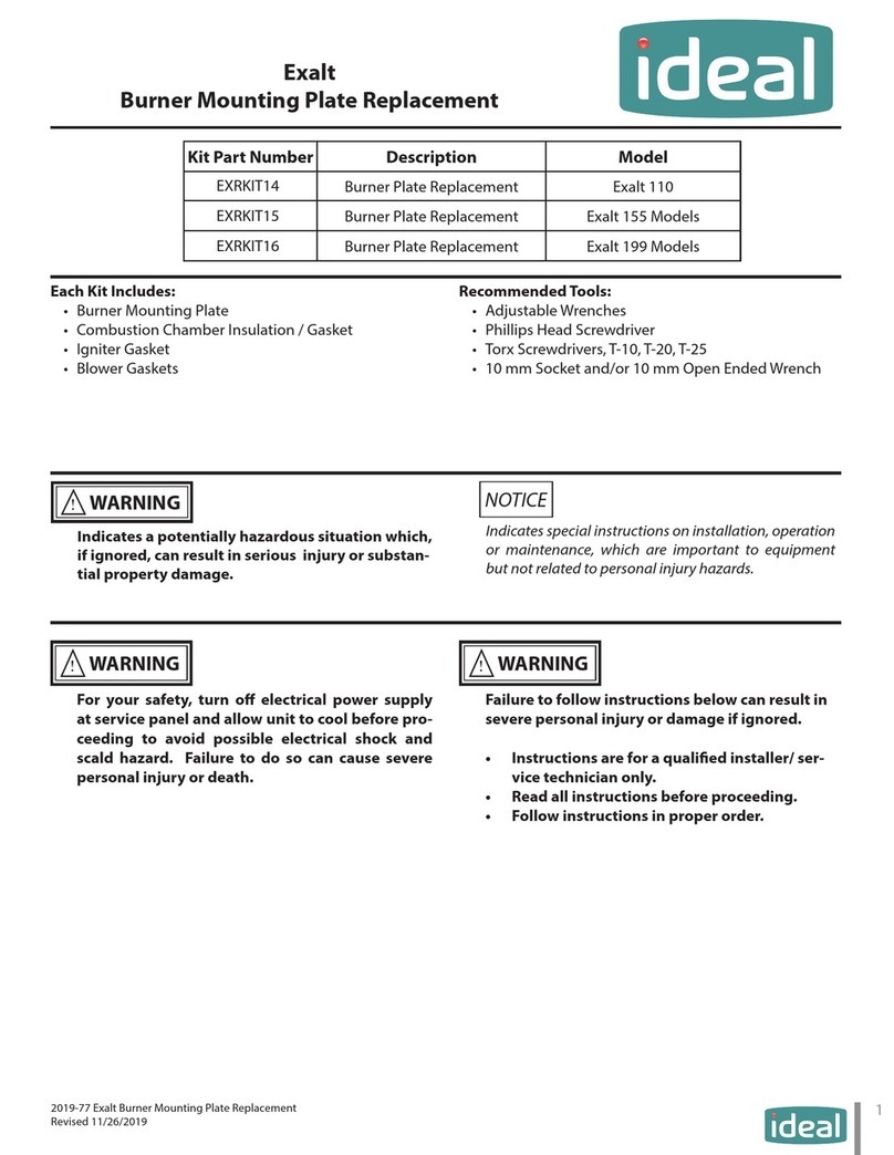
Kit Part Number Description Model
EXRKIT24Burner Replacement Exalt 110
EXRKIT25 Burner Replacement Exalt 155 & 199 Models
Each Kit Includes:
• Burner Head
• Burner Head Gasket
• Three (3) Burner Screws
Recommended Tools:
•Adjustable Wrenches
• Phillips Head Screwdriver
• Torx Screwdrivers
• 10 mm Socket and/or 10 mm Open Ended Wrench
2019-72 Exalt Burner Head Replacement
Revised 11/26/2019
Exalt
Burner Head Replacement
2
1. Preliminary Instructions
1. Verify that the insulation replacement kit is correct
for the model of boiler. See table on page 1.
2. Carefully open and unpack the PARTS BOX from its
shipping carton.
3. Carefully remove and check for any damage.
NOTICE
Installing damaged insulation/gasket will cause
malfunction of the boiler. Contact IdealUSA right away if
the insulation/gasket is damaged in any way.
4. Turn o the electrical power supply to the boiler.
5. Close the manual gas shut o valve to the unit.
2. Removal of the old Burner Head
1. Turn power to the unit“OFF”and allow unit to cool.
2. Shut o gas supply to the inlet of the unit at the
main manual shuto valve to the unit.
3. Remove front jacket panel on the top of the boiler
4. Disconnect all the wires from the gas valve, blower
and igniter.
NOTICE
Mark the proper location of all wires before removing them.
5. Remove the air inlet elbow from the venturi. Leave
the elbow attached to the air inlet connection at
the top of the boiler.
6. Disconnect the gas supply piping to the venturi.
Unscrew the nut on either the venturi or the gas
valve. Do not discard the gasket as they will be re-
used.
7. Unbolt the four bolts securing blower from the
burner mounting plate. Do not discard the blower
gaskets. Do not discard the bolts as they will be re-
used. Remove the blower/venturi/gas pipe assem-
bly from the boiler.
Fig. 1: Exalt 110 Burner Assembly
Fig. 2: Exalt 155 Burner Assembly
Exalt
Burner Head Replacement
3
Fig. 3: Exalt 199 Burner Assembly
8. Remove the two screws securing the igniter to the
mounting plate. Do not discard the screws or ignit-
er gasket as they will be reused. Remove the igniter
out carefully.
NOTICE
Ensure to not damage the igniter. Contact IdealUSA
right away if the igniter is damaged in any way.
9. Remove the nuts securing the burning mounting
plate to the rear jacket panel. These screws are for
shipping protection and can be discarded.
10. Remove the burner plate mounting nuts. Do not
discard the nuts as they will be reused.
11. Remove the burner mounting plate straight up
from the heat exchanger body to ensure the insu-
lation is not damaged. Keep the insulation installed
in the heat exchanger.
12. Remove the three screws securing the burner head
to the bottom of the mounting. Discard the screws
and gasket.
3. Installation of the new Burner Head
1. Install the new burner, burner gasket, and screws
onto the burner mounting plate. Ensure the at
portion of the burner head is towards the igniter
cutout. Tighten the screws to 26.5 to 31 in-lbs of
torque.
NOTICE
If the igniter or sightglass cutout are covered in anyway by
the burner head, remove and reinstall the burner head so
that there is no overlap.
NOTICE
For the reassembly process do not use adhesives on ANY gas-
ket surface.
WARNING
!
Ensure the gasket is in place before reassembly. Fail-
ure to do so can result in death, serious injury or sub-
stantial property damage.
2. Carefully reinsert the burner assembly into the
heat exchanger body. Align the burner assembly
igniter and sightglass cutout with the combustion
chamber insulation igniter and sightglass cutout.
NOTICE
Ensure to not damage the insulation block or burner
head during re-installation. Contact IdealUSA right away
if the igniter is damaged in any way.
3. Reinstall the igniter gasket, igniter, and igniter
screws. Tighten the screws to 26.5 to 31 in-lbs of
torque. Ensure the green grounding cables are
connected.
NOTICE
Ensure to not damage the igniter. Contact IdealUSA
right away if the igniter is damaged in any way.
4. Hand tighten the Burner Plate Mounting Nuts to
hold the burner assembly in place. Then using a
Exalt
Burner Head Replacement
4
wrench tighten each nut to 44-53 in-lbs.
WARNING
!
Do not over tighten. Pinching or tearing of the burner
plate gasket may occur causing the possible escape of
combustion gases from the combustion chamber re-
sulting in death, serious injury or substantial property
damage.
5. Reinstall the blower gaskets onto the burning
mounting plate and reattach the blower/venturi/
gas line to the burner mounting plate. Tighten the
blower bolts to 62-71 in-lbs of torque.
WARNING
!
Ensure the gasket is in place before reassembly. Fail-
ure to do so can result in death, serious injury or sub-
stantial property damage.
6. Re-connect the gas supply piping to the venturi.
Ensure the pipe gasket is properly seated before
tightening the nut.
WARNING
!
Ensure the gasket is in place before reassembly. Fail-
ure to do so can result in death, serious injury or sub-
stantial property damage.
7. Reattach the air inlet elbow to the venturi.
8. Re-attach all the wires to the gas valve, blower and
Igniter.
9. Turn on gas supply to the inlet of the unit at the
main manual shuto valve to the unit. Check and
test all gas connections for leaks. Repair leaks if
found.
WARNING
!
Do not check for gas leaks with an open flame. Use a
bubble test. Failure to check for gas leaks can cause
severe personal injury, death or substantial property
damage.
10. Turn power to the unit “ON”. The unit is now ready
to be placed back into service.

This manual suits for next models

1

Other IDEAL Burner manuals

IDEAL Exalt Series Operating and safety instructions

IDEAL

IDEAL Exalt Series Operating and safety instructions

Popular Burner manuals by other brands

BRAND-MAN Rustler 2 BG2211A6 owner's manual

BRAND-MAN

BRAND-MAN Rustler 2 BG2211A6 owner's manual

DCS BGA131 Use and care guide

DCS

DCS BGA131 Use and care guide

Riello DB9 LSM C13 TC FB FS1 A0 T150 DUAL IGNITION Installation, use and maintenance instructions

Riello

Riello DB9 LSM C13 TC FB FS1 A0 T150 DUAL IGNITION Installation, use and maintenance instructions

Ecoflam MAIOR P 15 AB manual

Ecoflam

Ecoflam MAIOR P 15 AB manual

baltur BT 40 DSN 4T INSTALLATION, USE AND MAINTENANCE INSTRUCTION MANUAL

baltur

baltur BT 40 DSN 4T INSTALLATION, USE AND MAINTENANCE INSTRUCTION MANUAL

Riello RX35 S/PV H Installation, use and maintenance instructions

Riello

Riello RX35 S/PV H Installation, use and maintenance instructions

Weber Genesis 2000 Accessory installation guide

Weber

Weber Genesis 2000 Accessory installation guide

TriangleTube PSRKIT38 instructions

TriangleTube

TriangleTube PSRKIT38 instructions

Beckett CF375 user manual

Beckett

Beckett CF375 user manual

Ferroli SUN M10 Operating, installation and maintenance instructions

Ferroli

Ferroli SUN M10 Operating, installation and maintenance instructions

Cuisinart 85-3112-4 Care & safety instructions

Cuisinart

Cuisinart 85-3112-4 Care & safety instructions

CIB UNIGAS HTLX115 installation manual

CIB UNIGAS

CIB UNIGAS HTLX115 installation manual

YOKOI KIKAI KOSAKUSHO HOPE CJ Handling manual

YOKOI KIKAI KOSAKUSHO

YOKOI KIKAI KOSAKUSHO HOPE CJ Handling manual

Wayne EHA manual

Wayne

Wayne EHA manual

Empire Comfort Systems FDR30LBP-2 Installation instructions and owner's manual

Empire Comfort Systems

Empire Comfort Systems FDR30LBP-2 Installation instructions and owner's manual

Conrad Electronic DJ061 operating instructions

Conrad Electronic

Conrad Electronic DJ061 operating instructions

Janfire Flex-a Installation and service

Janfire

Janfire Flex-a Installation and service

Smeg BQ6030 Instructions for the installer

Smeg

Smeg BQ6030 Instructions for the installer

manuals.online logo
manuals.online logoBrands
  • About & Mission
  • Contact us
  • Privacy Policy
  • Terms and Conditions

Copyright 2025 Manuals.Online. All Rights Reserved.