idi Aspect ISR G3 User manual
Made in the USA
idi
Image Diagnostics, Inc.
Manufacturers of Quality Medical Products
Aspect
100-4T G3 and ISR G3
Mobile Image Tables
Operator Manual

Operator Manual
Aspect 100-4T G3 and ISR
G3
L100-2843 28-MAR-2018 www.imagediagnostics.com i
The text of this manual was originally written, approved and published by the manufacturer in English.
OVERVIEW
This manual pertains to the specified devices only and does not intended to replace or substitute for certified
training in the application of this equipment. The device is intended for qualified medical personnel who
have been trained in the use of medical equipment.
Functional capabilities and operation of the equipment described herein can be employed in a variety of
diagnostic, therapeutic, and surgical applications. The device is designed for use as either a fluoroscopic or
radiographic table.
OWNER RESPONSIBILITIES
The owner of this device is responsible to ensure system compatibility, the qualifications of the operator and
maintenance personnel. The operator must be properly trained and have obtained credentials from the
appropriate authorities.
This equipment must be installed in an area provided with the proper electrical power.
The owner of this device is responsible for verifying continued compliance with all applicable regulations
and standards. Consult local, state, federal and/or international agencies regarding specific requirements and
regulations applicable to the use of this equipment.
Image Diagnostics, Inc. certifies only the equipment. After-sale operating practices and safety are the
responsibility of the owner and operator. Image Diagnostics, Inc. assumes no liability or responsibility for
after-sale operating or safety practices; nor can it be responsible for personal injury or damage resulting from
misuse.
Never make modifications or adjustments to the equipment unless directed by a qualified Image Diagnostics
representative. This equipment, when properly assembled, meets US federal regulations and international
standards. Unauthorized modifications to the equipment may impact adherence to these standards and make
the equipment unsafe to operate.
CUSTOMER SUPPORT
Image Diagnostics will make available, on request, circuit diagrams, component part lists, calibration
instructions, or other information which will assist the user’s appropriately qualified technical personnel to
repair those parts of equipment which are designated by the manufacturer as repairable.
For technical assistance, call IDI at (978) 829-0009 or send fax to (978) 829-0027. Be prepared to give the
complete model and serial number found on the data plate on the table base at the time of contact.
This X-ray component manufactured by Image Diagnostics, Inc. complies with applicable FDA performance
standards contained in 21CFR at date of manufacture.

Operator Manual
Aspect 100-4T G3 and ISR
G3
L100-2843 28-MAR-2018 www.imagediagnostics.com ii
Table of Contents
1. SYMBOL IDENTIFICATION............................................................................................. 1
2. INTENED USE & ESSENTIAL PERFORMANCE.......................................................... 3
3. SAFETY INSTRUCTIONS.................................................................................................. 3
4. SAFETY HAZARDS............................................................................................................. 4
5. EMC (Electromagnetic Compatibility) STATEMEMT .................................................... 6
6. EMERGENCY STOP PUSHBUTTON............................................................................... 7
7. SETUP INSTRUCTIONS & PATIENT PREPARATION ............................................... 7
7.1. Installation...................................................................................................................... 7
7.2. Preparation for Patient Use........................................................................................... 8
7.3. Patient Loading .............................................................................................................. 8
7.4. Preparation for Performing CPR................................................................................. 9
8. INSTRUCTIONS FOR TABLE OPERATION.................................................................. 9
8.1. CASTER MOTION AND STEERING SETTINGS................................................... 9
8.2. POWER INDICATOR LIGHT .................................................................................. 11
8.3. TABLE MOTION CONTROLS................................................................................. 11
8.4. TABLE TOP MOTION HANDSET CONTROLS................................................... 13
8.5. FOOT ACTUATED MOTION CONTROLS ........................................................... 15
9. STANDARD ACCESSORIES............................................................................................ 16
9.1. Patient Mattress Pad for Tabletop. ............................................................................ 16
9.2. Patient Restraint Straps............................................................................................... 16
10. ADD-ON ACCESSORIES.................................................................................................. 17
10.1. Clamp-on Accessory Rail......................................................................................... 17
10.2. Vascular Access Arm Board (VAB)........................................................................ 17
10.3. Quick Release Rail Mount Arm Board (requires Clamp-on Accessory Rail) .... 18
10.4. Arm Board, Shoulder Mount .................................................................................. 18
10.5. Tabletop Catheter Tray Extension ......................................................................... 18
10.6. Articulating Headrest Extension............................................................................. 19
10.7. Peripheral Headrest Extension................................................................................ 19
10.8. Radiation Shield........................................................................................................ 20
10.9. Anesthesia Screen Holder. (May require a pair of side rail clamps).................. 20
10.10. Side Rail Clamps, Rotating...................................................................................... 20
11. GENERAL CLEANING..................................................................................................... 21

Operator Manual
Aspect 100-4T G3 and ISR
G3
L100-2843 28-MAR-2018 www.imagediagnostics.com iii
12. MAINTENANCE, SERVICE & REPAIR........................................................................ 22
12.1. RECOMMENDED PERIODIC PERFORMANCE CHECKS............................ 22
12.2. SERVICE & REPAIR STATEMENT.................................................................... 22
13. TROUBLESHOOTING...................................................................................................... 23
14. DISPOSAL OF COMPONENTS....................................................................................... 26
15. PRODUCT DATA............................................................................................................... 27
16. SPECIFICATIONS............................................................................................................. 28
17. WARRANTY....................................................................................................................... 32

Operator Manual
Aspect 100-4T G3 and ISR
G3
L100-2843 28-MAR-2018 www.imagediagnostics.com 1
1. SYMBOL IDENTIFICATION
Attention! Consult accompanying documents.
Failure to follow these instructions could cause serious
personal injury or damage to equipment. CD ROMs
containing digital files of relevant drawings, BOMs, and
documentation are included with the service manual for
reference.
Warning! Information or instructions shown near this symbol must be adhered
to in order to prevent a potentially hazardous situation which if not avoided,
could result in death, personal injury or damage to the equipment.
Emergency Stop Pushbutton.
Electric Shock hazard. Information or instructions shown near this symbol
must be adhered to in order to prevent a potentially hazardous situation which
if not avoided, could result in death, personal injury or damage to the
equipment.
Equipotential Terminal of the table which provides for a connection between
the table and the equipotential bus bar of the facility.
Recyclable material.
There is the potential of exposure to harmful x-rays. Be sure to read and
comply with all warnings.
Not made with natural rubber latex.
Not for Patient Transport. The Table should not be relocated with a patient on
it nor should it be used to move a patient.
or

Operator Manual
Aspect 100-4T G3 and ISR
G3
L100-2843 28-MAR-2018 www.imagediagnostics.com 2
Protective Ground. This is the common tie point between the AC Electrical
Power Cord Ground, Frame Ground, and Controller Ground.
Patients must be loaded from the side of table. There is possible tilting or
instability if patient is loaded onto the pedestal end of table or the imaging end
of the table.
Presence of non-ionizing electromagnetic radiation.
European Authorized Representative:
Model of Table.
Serial Number of Table.
Indication of European Conformity for sale in the European Economic Area
(EEA).
Item complying to Type B applied part per IEC 60601-1.
Date of manufacture of the device.
Location where device was manufactured.
Alternating Current (AC).
Pressing in the Switch Lockout Pushbutton on the end of the Table Top
Motion Control Panhandle Unit will disable all the Rocker Switches on the
Unit. It DOES NOT lock out the lateral and longitudinal motion controlled by
the brake release lip underneath the mushroom shaped Panhandle Knob.
CPR (Cardiopulmonary resuscitation)
EC
REP
REF
SN
Advena Ltd. Pure Offices, Plato Close,
WARWICK CV34 6WE UK
Operator Manual
Aspect 100-4T G3 and ISR
G3
L100-2843 28-MAR-2018 www.imagediagnostics.com 3
2. INTENDED USE & ESSENTIAL PERFORMANCE
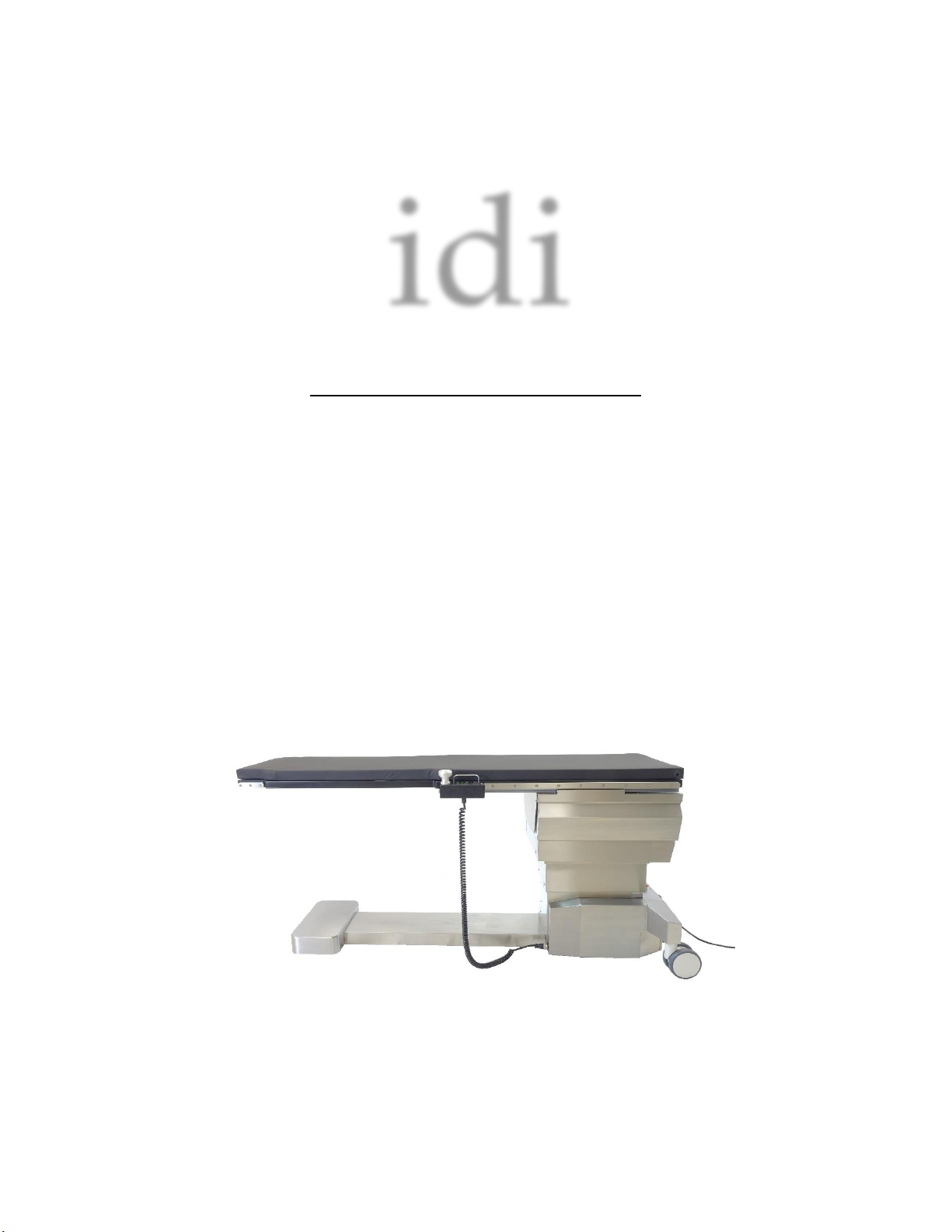
The Aspect ISR G3 & Aspect 100-4T G3 are mobile imaging tables used by the medical
industry for vascular surgery, endovascular procedures and interventional radiology.
They are designed to be used in a professional healthcare environment in conjunction
with “C-arm” style radiological imaging equipment. The tables have backup battery
power which should only be used temporarily for necessary function of the table if the
external power supply is disrupted.
3. SAFETY INSTRUCTIONS
✓All persons using this equipment must fully understand its operation instructions,
emergency procedures, capabilities including total range of motion and be aware of
all potential safety hazards.
✓This manual should be accessible to all personnel installing, operating, or servicing
this equipment.
✓Only a qualified technician may install or service this equipment.
Failure to follow safety precautions may result in serious injury to patient or
user or damage to equipment.
Comments and questions regarding safety should be addressed to:
Customer Support
Image Diagnostics, Inc.
310 Authority Drive
Fitchburg, MA 01420 USA
Or call IDI at (978) 829-0009 or Toll Free (877) 304-5434.
The fax number for IDI is (978) 829-0027.
Review the SAFETY HAZARDS and OPERATING
INSTRUCTIONS before operating table
Operator Manual
Aspect 100-4T G3 and ISR
G3
L100-2843 28-MAR-2018 www.imagediagnostics.com 4
4. SAFETY HAZARDS
Safety Hazard Level
Potential Consequences with Use
DANGER
Indicates an imminently hazardous situation which, if not
avoided, will result in death or serious injury.
WARNING
Indicates a potentially hazardous situation which, if not
avoided, could result in death or serious injury.
CAUTION
Indicates a potentiallyhazardous situation which, if not
avoided, may result in minor or moderate injury or
equipment damage.
WARNING!
This equipment has not been tested for use with high
frequency surgical equipment, cardiac defibrillators, or
cardiac defibrillator monitors. Use with such equipment
may cause patient burns, explosion hazards or
electrical shock to the patient or operator.
CAUTION
Do not leave patient unattended.
WARNING!
To avoid electric shock, plug the electrical power cord
into a properly grounded hospital grade outlet!
WARNING!
This product may be used in conjunction with x-ray
equipment. This constitutes potential exposure to
harmful x-rays for both the patient and operator. Be
sure to use proper radiation shielding.
WARNING!
If an antistatic path is required, use this equipment on
an antistatic floor.
Use only the Patient Mattress Pad supplied with the
table.
Operator Manual
Aspect 100-4T G3 and ISR
G3
L100-2843 28-MAR-2018 www.imagediagnostics.com 5
WARNING!
Safely position and secure patient onto table.
Do not exceed table weight capacity of 600 pounds
(272kg).
CAUTION
The carbon fiber top is subject to damage or possible
damage from impact from other objects.
Take caution when moving the table or using power
driven diagnostic equipment around table. Collisions
with nearby equipment can cause equipment damage or
patient harm. Regular inspection of the tabletop is
necessary for the safety of patient and operator.
CAUTION
During operation of the table, if any unusual sounds
and/or erratic movement is observed, immediately
discontinue use of the table.
CAUTION
Do not use table for patient transport.
CAUTION
Do not place or store any containers or large items
underneath the tabletop. As the tabletop is descending,
contact with an obstruction may cause permanent
damage to the table.
CAUTION
When lying on the table, patient must be restrained at
all times. The restraining straps are not intended to
restrain an uncontrolled patient.
WARNING!
Use of table extensions is only allowed with decreased
table load. Table weight capacity reduced to 500 pounds
(227kg) when using table extension.

Operator Manual
Aspect 100-4T G3 and ISR
G3
L100-2843 28-MAR-2018 www.imagediagnostics.com 6
5. EMC (Electromagnetic Compatibility) STATEMENT
Portable and Mobile RF Communications Equipment can affect Medical Electrical
Equipment including the Aspect 100-4T G3 and Aspect ISR G3 tables. Use special precautions
regarding EMC when these tables are installed, operated and maintained. EMC operating
specifications for these tables are in the SPECIFICATIONS section of this manual (Section 16).
The use of accessories, transducers and/or cables other than those specified, with the
exception of those sold by the manufacturer as replacement parts for internal components, may
result in increased emissions or decreased immunity of the equipment or system.
WARNING: The Aspect 100-4T G3 or Aspect ISR G3 should not be used
adjacent to or stacked with other medical electrical equipment and that if adjacent
or stacked use is necessary, the equipment or system should be observed to verify
normal operation in the configuration in which it will be used.
WARNING: Portable RF communications equipment (including peripherals
such as antenna cables and external antennas) should be used no closer than 30
cm (12 inches) to any part of the Aspect 100-4T G3 or Aspect ISR G3, including
cables connected to the table. Otherwise, degradation of the performance of this
equipment could result.
NOTE: The emissions characteristics of this equipment make it suitable for use in
industrial areas and hospitals (CISPR 11 class A). If it is used in a residential environment (for
which CISPR 11 class Bis normally required) this equipment might not offer adequate protection
to radio-frequency communication services. The user might need to take mitigation measures,
such as relocating or re-orienting the equipment.
If this equipment receives excessive electromagnetic interference, motion controls for
the table may be slow or unresponsive to user inputs. In this event,
1. Verify the cause by turning nearby equipment off and retest motions. (Note: All
motions will be slowed when operating on battery backup as compared to full
AC power)
2. If this problem is not resolved, immediately remove power to the equipment by
engaging the Emergency Stop Pushbutton as shown in section 6 of this manual.
3. Notify IDI customer service using the contact information in the section 6 of
this manual.
CAUTION
Applying pressure to the side of the tabletop more than
70 pounds of force can overcome the braking system
causing the tabletop to move.
Operator Manual
Aspect 100-4T G3 and ISR
G3
L100-2843 28-MAR-2018 www.imagediagnostics.com 7
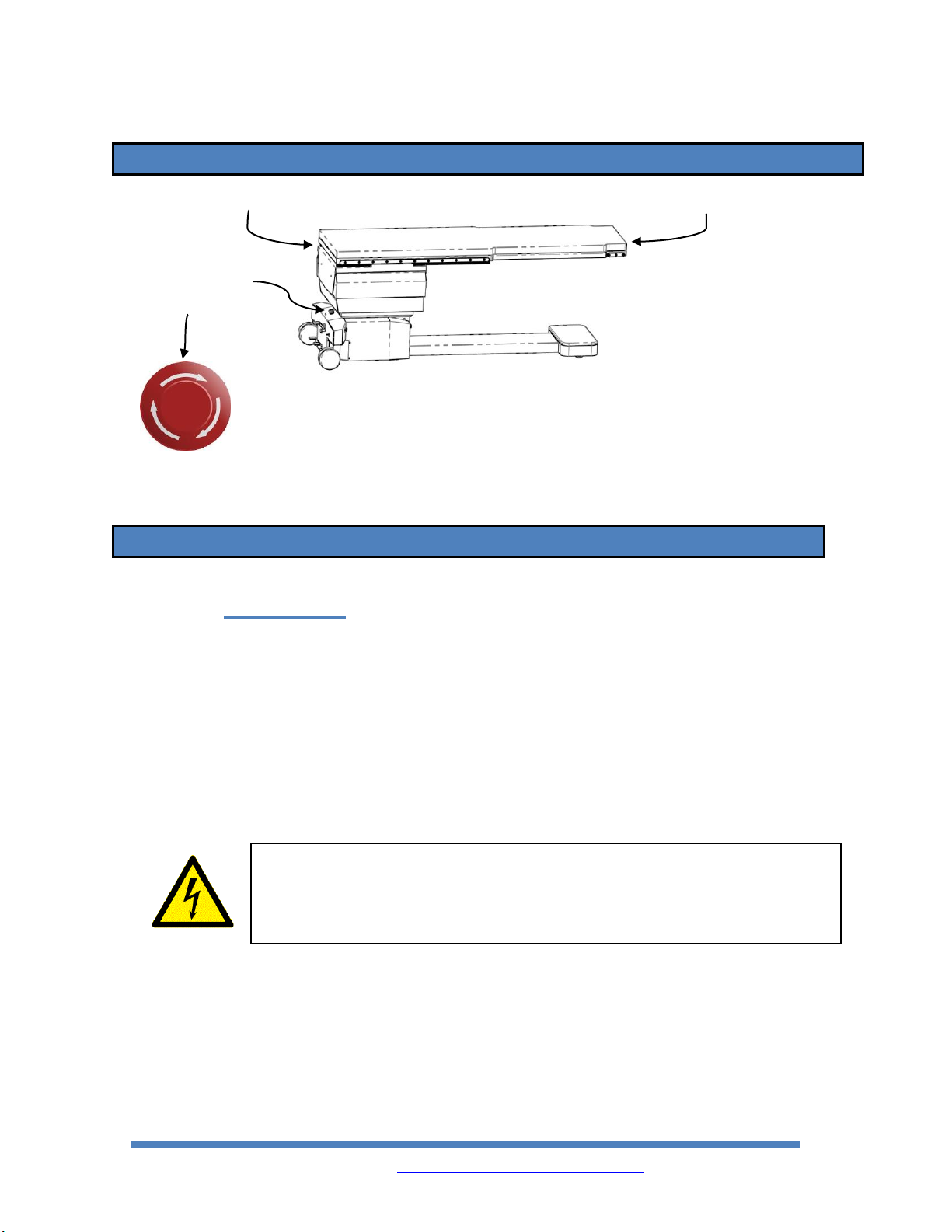
6. EMERGENCY STOP PUSHBUTTON
➢The red Emergency Stop Pushbutton is located in the center of the
base cover on the back of the table.
➢Pressing this button until it is fully engaged will stop all motorized
movement by removing power from all system components.
• ACTIVATE: Engage the emergency stop mode by pressing the button.
• RESET: Restore the electrical functions by rotating the button a quarter turn.
7. SETUP INSTRUCTIONS & PATIENT PREPARATION
7.1. Installation
•Hand operated controls for the movement of the tabletop are included with the table. The
operator should become familiar with the controls before using them.
•External electrical power connection and disconnection is through the AC power cord and
outlet. The table will operate on 110 V~, 230 V~ or on internal battery backup power. When
external electrical power is applied to the actuators which control the movement of the
tabletop, the green LEDs on the Handset Control will illuminate.
•The electrical power outlet used should be visible and accessible to the user. The electrical
power cord should be routed where it will not be subject to damage or be a tripping hazard.
•Check that the ground pin on the electrical cord plug is in good condition before each time
that it is plugged in.
WARNING!
To avoid electric shock, plug the electrical power cord
into a properly grounded hospital grade outlet!
EMERGENCY
STOP
PUSHBUTTON
PEDESTAL END OF TABLETOP
IMAGING END OF TABLETOP

Operator Manual
Aspect 100-4T G3 and ISR
G3
L100-2843 28-MAR-2018 www.imagediagnostics.com 8
•When the table is not connected to AC power, the table will automatically switch to backup
battery mode. The table should only be used under backup battery power temporarily for
necessary function if the external power supply is lost.
•It is recommended that AC power be applied for a minimum of 8 hours every day to keep a
proper charge on the batteries and achieve maximum battery life. Batteries are constantly
being charged during normal use when connected to AC power.
When the table is not in use and not connected to AC power, the Emergency
Stop Pushbutton must be fully engaged to prevent the batteries from being
discharged and to safely power off the equipment.
•The Aspect 100-4T G3 and Aspect ISR G3 table top braking systems utilize a passive magnetic
brake; it remains engaged/energized in the event of a complete loss of electrical power. Power
is necessary to release the brakes.
•As the braking system utilizes permanent magnetic brakes, braking force is limited by the
magnet strength. Use caution when applying pressure to the side of the table as the brakes can
be overcome if more than 70 pounds of force is applied.
7.2. Preparation for Patient Use
•New Installation: This equipment will need to be properly cleaned before patient use as it will
inevitably come into contact with contaminants during shipping, unpacking, storage, and
installation.
•After Installation: This equipment will need to be properly cleaned between uses with patients
as it will inevitably come into contact with contaminants during procedures. Refer to section
11 of this manual for cleaning instructions and approved cleaning substances.
7.3. Patient Loading
CAUTION
If the tabletop is struck hard enough, it may slide
to reduce damage to the carbon fiber top.

Operator Manual
Aspect 100-4T G3 and ISR
G3
L100-2843 28-MAR-2018 www.imagediagnostics.com 9
•Patients must be loaded from the side of table. There is a possibility of tilting,
instability and/or tipping if patient is loaded onto the pedestal end of Table or the
imaging end of the Table.
•To reduce potential motion during patient transfers with larger patients, move the Table Top
lateral (side to side) in the direction the patient will be moving until the limit of the table top
travel is reached, release the Panhandle Tabletop Float Break to re-engage the break and then
transfer the patient onto the Table.
7.4. Preparation for Performing CPR
•Return table to level position, retract tabletop to
minimize overhang and lower table position to a
comfortable height before performing CPR on a patient.
8. INSTRUCTIONS FOR TABLE OPERATION
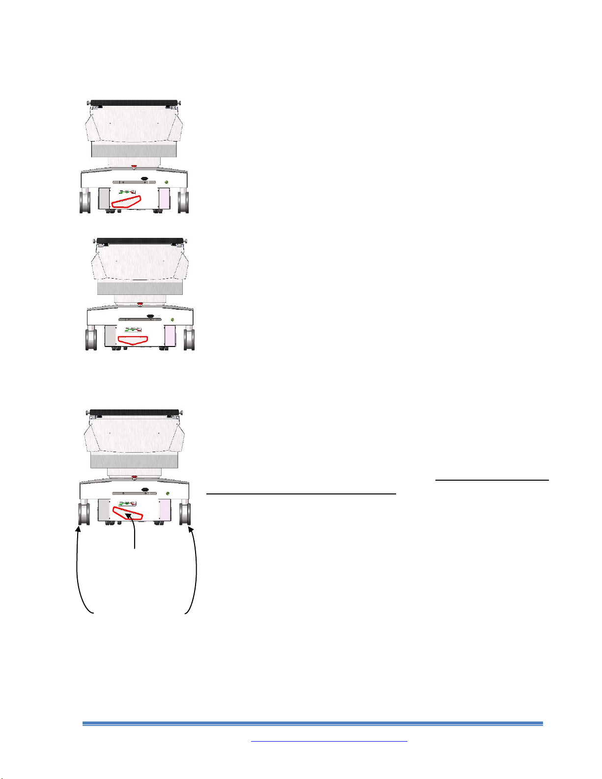
8.1. CASTER MOTION AND STEERING SETTINGS
The motion of the table can be configured three ways so that the rear casters are locked to roll
only forwards or backwards only along the length of the table (“STEER”), be free rolling in all
directions (“FLOAT”) or set so that it will not be able to roll at all (“LOCK”).
WARNING!
Before loading a patient onto the table, always set the
caster motion pedals in the “LOCK” position. Failure to
do so could result in death or serious injury.
Operator Manual
Aspect 100-4T G3 and ISR
G3
L100-2843 28-MAR-2018 www.imagediagnostics.com 10
The Table is in “STEER” mode when the Caster Lock Pedal is pushed
down on the left side to its lowest position. The Rear Casters will lock
into a forward/backwards direction for ease of maneuvering when moving
the Table. If the Rear Casters are not oriented front to back when the
“STEER” position is selected, they will pivot as the Table is moved until
they are pointing front to back and then they stay locked in that position.
The Table is in “FLOAT” mode when the Caster Lock Pedal is in a level
position. The Front and Rear Casters can roll freely in any direction.
The Table is in “LOCK” mode when the Caster Lock Pedal is pushed
down on the right side to its lowest position. The Rear Casters will be
totally locked and will not roll in any direction. Always lock all casters
in this way before loading the patient.
CASTER
LOCK
PEDAL
REAR CASTERS

Operator Manual
Aspect 100-4T G3 and ISR
G3
L100-2843 28-MAR-2018 www.imagediagnostics.com 11
8.2. POWER INDICATOR LIGHT
The Power Indicator Light, located just below the
Emergency Stop Pushbutton on the back side of the
Table will be illuminated green when there is sufficient
electrical power to the Table and unlit when there is no
electrical power to the Table or when the Emergency Stop
Pushbutton is engaged.
8.3. TABLE MOTION CONTROLS
All Aspect ISR G3 & Aspect 100-4T G3 tables are equipped with tabletop motion control boxes that
allow users to move the tabletop in many different directions.
Continually pressing down on the Rocker Switch to the right
of this symbol will raise the Table Top vertically.
Continually pressing down on the Rocker Switch to the right
of this symbol will lower the Table Top vertically.

Operator Manual
Aspect 100-4T G3 and ISR
G3
L100-2843 28-MAR-2018 www.imagediagnostics.com 12
Continually pressing down on the Rocker Switch to the right
of this symbol will tilt up the imaging end of the Table Top
in a Trendelenburg direction.When the Table Top reaches
a level position, motion will stop for 1 second. When the
Rocker Switch is pressed down if the Table Top is already in
a level position, it will take 1 second for motion to begin.
Continually pressing down on the Rocker Switch to the right
of this symbol will tilt down the imaging end of the Table
Top in a Trendelenburg direction.When the Table Top
reaches a level position, motion will stop for 1 second. When
the Rocker Switch is pressed down if the Table Top is
already in a level position, it will take 1 second for motion to
begin.
Continually pressing down on the Rocker Switch to the right
of this symbol will roll the Table Top in a clockwise
direction if looking down the length of the Table from the
pedestal end. When the Table Top reaches a level position,
motion will stop. The Rocker Switch will needto be released
and pressed down again for the motion to begin again.
Continually pressing down on the Rocker Switch to the right
of this symbol will roll the Table Top in a counter-clockwise
direction if looking down the length of the Table from the
pedestal end. When the Table Top reaches a level position,
motion will stop. The Rocker Switch will needto be released
and pressed down again for the motion to begin again.
Pressing in the Switch Lockout Pushbutton on the end of the
Motion Control Unit next to this symbol until it is fully
engaged will disable all the switches on the Motion Control
Unit. It DOES NOT lock out the lateral and longitudinal
motion controlled by the mushroom shaped Panhandle Float
Brake.
Operator Manual
Aspect 100-4T G3 and ISR
G3
L100-2843 28-MAR-2018 www.imagediagnostics.com 13
Lifting the lip under the mushroom shaped Panhandle releases
the brakes that stop all lateral and longitudinal motion of the
Table Top. Holding the ring up with fingertips allows the
Table Top to be manually repositioned. The Switch Lockout
Pushbutton only disables Elevate, Trendelenburg, and ISO-
Centric Roll (ISR G3 only) motions to prevent accidental
activation.
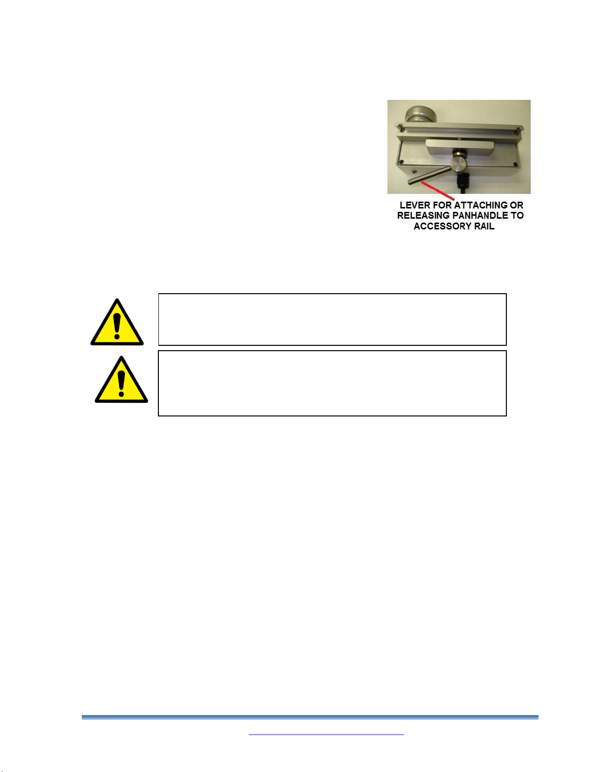
The Table Top Motion Control Unit clamps onto either the left
or right Accessory Rail on the Table Top and can be moved
along the length of the rails by rotating the lever down on the
bottom of the Motion Control Unit until the clamp releases
tension on the Accessory Rail. Then the Unit can be slid along the rail or removed.
8.4. TABLE TOP MOTION HANDSET CONTROLS
WARNING!
The Handset Control is always active when
connected to a powered-up table.
WARNING!
The Switch Lockout Pushbutton on the Motion
Control Panhandle does not disable the Handset
Control.

Operator Manual
Aspect 100-4T G3 and ISR
G3
L100-2843 28-MAR-2018 www.imagediagnostics.com 14
•When using the Handset Control shown above, each button must be held down to get
continuous motion of the tabletop. Motions will stop as soon as the button is released.
•When the Trendelenburg (tilt) function buttons are used, the Table Top motion will stop at
level position for 1 second before motion begins again. When the Table’s Trendelenburg
(tilt) position is already level and the Trendelenburg buttons are pressed, it will take 1
second before the motion of the Table Top begins.
•When the ISO-Roll function buttons are used, the Table Top motion will stop at level
position. When this happens, release and repress the button again to continue the motion.
Operator Manual
Aspect 100-4T G3 and ISR
G3
L100-2843 28-MAR-2018 www.imagediagnostics.com 15
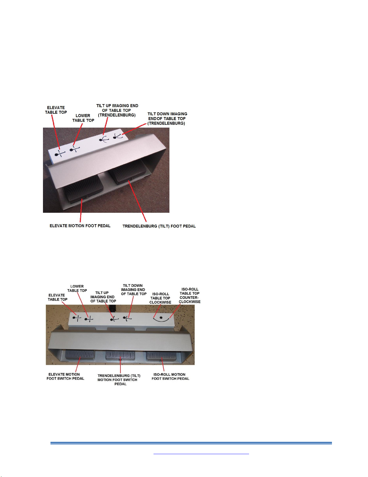
8.5. FOOT ACTUATED MOTION CONTROLS
100-4T G3 FOOT SWITCH CONTROL
Foot Switch activated control motions for the
Aspect 100-4T G3 Table Top are: elevate/lower
and Trendelenburg down/up. (Safety hood helps
avoid accidental motorized table movement
from Foot Switch).
•When the Trendelenburg Foot Pedal is
used, the tabletop motion will stop at level
position for 1 second before motion begins
again. When the Table’s Trendelenburg
position is already level and the Trendelenburg
Foot Pedal is pressed, it will take 1 second
before the motion of the Table Top begins.
ISR G3 FOOT SWITCH CONTROL
Foot Switch activated control motions for the
Aspect ISR G3 table are: ISO-Roll,
Trendelenburg down/up and elevate/lower.
(Safety hood helps avoid accidental motorized
Table movement from Foot Switch Control).
•When the Trendelenburg Foot Switch Pedal
is used, the Table Top motion will stop at
level position for 1 second before motion
begins again. When the Table’s
Trendelenburg position is already level and
the Trendelenburg Foot Switch Pedal is
pressed, it will take 1 second before the
motion of the tabletop begins.
•When the ISO-Roll Foot Switch Pedal is
used, the Table Top motion will stop at
level position. When this happens, release
and repress the ISO-Roll Foot Switch Pedal
again to continue the motion.

Operator Manual
Aspect 100-4T G3 and ISR
G3
L100-2843 28-MAR-2018 www.imagediagnostics.com 16
9. STANDARD ACCESSORIES
9.1. Patient Mattress Pad for Tabletop.
The Patient Mattress Pad is held in place by hook and loop fasteners. To remove the pad, simply
pull pad up gently to remove. Replacement pads are supplied with new self-adhesive fasteners
installed and new adhesive backed mating pieces for the tabletop. Peel off old fasteners from
Table Top. Peel off the protective paper and carefully put new pad into position. Apply pressure
to complete installation.
Note: Pad complies with California Technical Bulletin 117.
9.2. Patient Restraint Straps.
The Patient Restraint Straps can be
used in two different ways depending
on where the strap is to be located
along the length of the Table Top. If
the strap is to be used on the end of the
table that has the two long accessory
rails, then the whole strap drapes over
the Table Top, hangs down between the
rails and the tabletop and wrapped over
the outside of the rails to meet over the
top of the table. If the strap is to be
used along the rest of the tabletop, slide
the strap over the end of the table with
the thin part of the strap over the Table
Top and the thicker part under the
tabletop. The ends of the strap meet
over the top of the table and connect
with hook and loop fasteners.
WARNING!
Strap configuration is recommended; however, patient
restraint is a case-by-case condition. Please refer to
the facility’s policy on restraining a patient.
Other manuals for Aspect ISR G3
3
This manual suits for next models
1
Table of contents
Other idi Indoor Furnishing manuals


