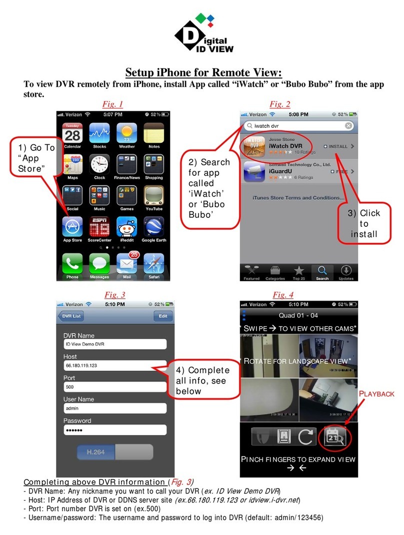
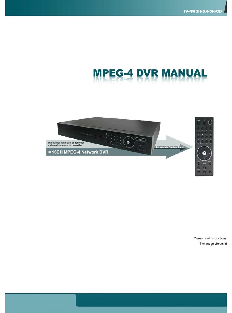
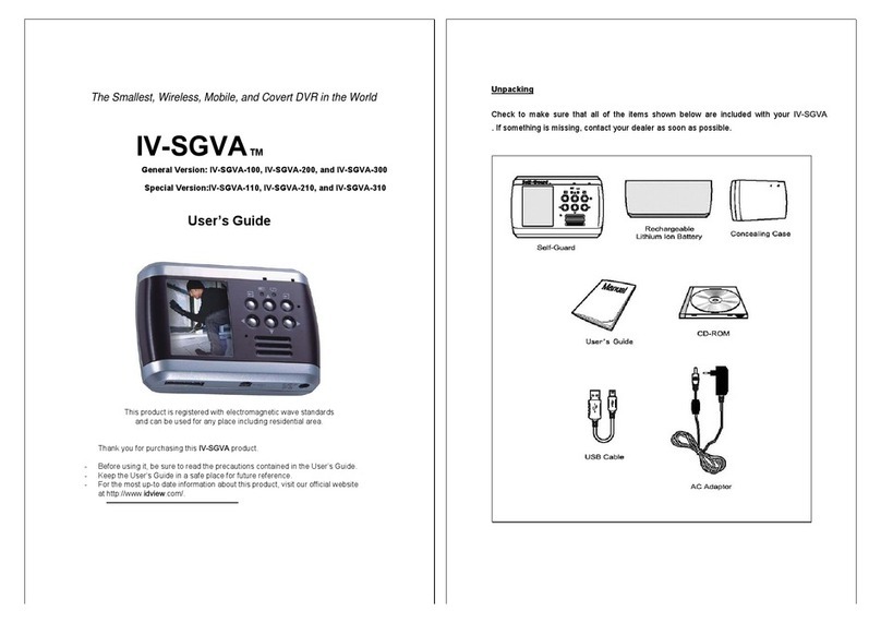
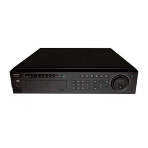
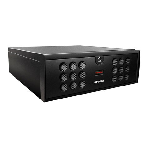
Idview Digital i Alarm DVR Operator's manual


User Instruction Manual
3
Introduction
Welcome to use the upgrade EAVS based on the "triple play" of DVR.
EAVS’s full name is Enternet -Alarm Video Server, ie, digital network
alarm video server, which is based on the embedded hardware and
software-based application technology, combined with advanced alarm
technology and H.264 video compression technology, all-digital, networked,
intelligent video surveillance alarm system.
EAVS embedded server integrates video recording and video services,
CPU hard pressure mode, using a higher level of H.264 compression standard,
the user can make the same image quality obtained under conditions of lower
compression rate,which effectively solves the problems of alarm expansion,
transmission, video compression, storage, remote control aspects of rational
distribution, independent alarm video services software and WEB video
services platform, easily realizes video linkage alarm, alarm video control, PTZ
control, remote set query.The system uses the Linux operating system, to
ensure the system stability and reliability, with a variety of network interfaces,
using TCP / IP protocol, LAN, WAN remote transmission automatic warning,
automatic alarm, automatic recording and other functions.
EAVS’s highly integrated features effectively solve the close tie between
the alarms and video ,automatic warning, alarm and video functions can be
achieved in the LAN and WAN. Through this alarm video services platform,
users can remotely set the alarm and video services, query and manipulate,
remote query alarm events.
EAVS’s entirely English operating platform, control software and remote
operating platform, powerful display control functions and a simple and
intuitive user interface and the remote host, make the system configuration
and operating procedures more straightforward, at the same time the
company carried on the operator interface beautification and hierarchical
segmentation, so that operation becomes easy.

User Instruction Manual
4
High level of integration reduces the maximum extent of a single modular
variety of devices, which reduces the linkage module and other external
devices, and greatly reduces the cost of system integration.In the process of
the formation of the system, due to relatively high integration, labor costs,
supplies, cost of intermediate devices are greatly reduced , making the EAVS
system more economical.
EAVS’s birth has opened alarm remote visualization prelude to the era,
which effectively solves the problem of false positives field detector
occurrence, breaking the traditional sense of the concept of on-site alarm,
allowing users to really experience security and reliability of alarm for the first
time.It is an important milestone of alarm into digital and remote visualization ,
alarm and video surveillance is a powerful combination of proven , intelligent
alarm monitoring is an important direction for future development, but also the
establishment of large-scale technology base alarm monitoring system.With
the large-scale development of intelligent alarm monitoring for urgent needs,
EAVS digital alarm surveillance video server plays a great role in
promoting.The set up of EAVS digital video platform builds a more efficient
implementation of the intelligent platform for security and peace which
provides the strongest protection for the future.
To facilitate this product can better serve you, we recommend that you
carefully read the user manual.Valuable suggestions and comments are
welcomed in the course of using this product.We always provide you with
careful and thoughtful service. If you have any questions please contact us.
We will not notice if there is a change of product performance, if you
want to know the latest features, please contact with the relevant
business.

User Instruction Manual
5
Contents
Chapter 1 Function and Features...............................................................................................1
Chapter 2 Specifications and interface definitions.....................................................................5
2.1 Attentions.............................................................................................................................5
2.2 Open Package and Accessories Inspection.........................................................................6
2.3 Pre Installation Instructions..................................................................................................7
2.4 Performance Parameters...................................................................................................13
2.5 Connection Diagram..........................................................................................................14
2.6 System Connection Diagram.............................................................................................15
2.7 Remote Controller Description...........................................................................................17
2.8 Mouse Operation................................................................................................................20
Chapter 3 Host Operation........................................................................................................22
3.1 Menu of Host System.........................................................................................................22
3.2 System of Settings and Operation......................................................................................23
3.2.1 User Log in.......................................................................................................................23
3.2.1.1 Host start up.................................................................................................................23
3.2.1.2 System Log in...............................................................................................................23
3.3 Menu Operations ...............................................................................................................24
3.3.1 System Configuration......................................................................................................24
3.3.1.1 Basic Setting................................................................................................................25
3.3.1.2 User Setting.................................................................................................................26
3.3.1.3 HDD Setting.................................................................................................................27
3.3.1.4 Default Setting..............................................................................................................28
3.3.1.5 System Operation........................................................................................................28
3.3.1.6 System Maintenance........................................................................................................29
3.3.2 Zone Configuration..........................................................................................................29
3.3.2.1 Basic Setting................................................................................................................29
3.3.2.1.1 Setup Remote Controller...........................................................................................29
3.3.2.1.2 Zone Setting..............................................................................................................30
3.3.2.1.3 System Setting..........................................................................................................32

User Instruction Manual
6
3.3.2.1.4 Setup CMS................................................................................................................34
3.3.2.1.5 Setup User( Voice) Phone No...................................................................................34
3.3.2.1.6 Password Setup........................................................................................................36
3.3.2.1.7 GPRS Setup..............................................................................................................37
3.3.2.2 Alarm Link Setup..........................................................................................................38
3.3.2.3 Timing Arm/Disarm.......................................................................................................40
3.3.2.4 Alarm(Remote / Zone) Query.......................................................................................41
3.3.3 Alarm Configuration.........................................................................................................42
3.3.3.1 Motion Detection..........................................................................................................42
3.3.3.2 Video Loss...................................................................................................................45
3.3.3.3 HDD Loss.....................................................................................................................45
3.3.3.4 Video Blind ..................................................................................................................45
3.3.4 Electric Switch.................................................................................................................46
3.3.5 Simulation.......................................................................................................................48
3.3.5.1 Encoding Setting..........................................................................................................48
3.3.5.2 Recording.....................................................................................................................49
3.3.5.3 PTZ..............................................................................................................................50
3.3.5.4 Mosaic Setting..............................................................................................................53
3.3.5.5 Timing Color.................................................................................................................53
3.3.5.6 Polling Setting..............................................................................................................54
3.3.6 Digital Camera Setting....................................................................................................55
3.3.7 Network...........................................................................................................................56
3.3.7.1 DHCP(Dynamic Host Configuration Protocol) Configuration.......................................56
3.3.7.2.1 PPPoE Configuration..............................................................................................58
3.3.7.2.2 DDNS........................................................................................................................58
3.3.7.2.3 FTP Configuration.....................................................................................................60
3.3.7.2.4 Mail Configuration.....................................................................................................61
3.3.7.3 CMS configuration........................................................................................................62
3.3.7.4 Time Syn......................................................................................................................63
3.3.7.5 IP Filter.........................................................................................................................63

User Instruction Manual
7
Chapter 1 Functions and Features
1.Basic Functions
▲It is based on an Embedded Linux operation system, which supports
browsing by the windows IE explorer and mobile phone.
▲It uses H.264 hardware compression technology with high compression
ratio and flexible handling.
▲It supports at most 16 channels video input,1 channel BNC video output ,1
channel VGA video output and 1 channel HDMI output.
▲It supports RS-485 interface ,which may control PTZ and reliable multiple
decoding protocol extension.
2.Compression Functions
▲Video compression uses H.264 compression algorithm,which may realize
independent hardware compression with CIF resolution of 25 frames per
second.It supports both VBR and variable frame rate.The coded stream of
video image can be set during the process of setting the quality of video
image.
▲It supports at most 16 channels audio/video signals.Each channel of
audio/video signal is compressed in real time by independent hardware to
ensure the stable synchronization of sound and image.
▲It supports QCIF/CIF/D1/HD1 /960H/720P resolutions.
3.Storage and Backup Functions
▲There are 2 -6 SATA hard disk interface and all of them support TB-level
hard disk.
▲Backup through USB port like flash disk or portable hard disk
▲As for client computers, the backup process can be done through
downloading the files from the hard disk.

User Instruction Manual
8
▲It adopts the hibernation treatment for the non-working hard disk, which
favors the heat dissipation and power consumption reduction,and
consequently prolong the HDD service life.
▲Files on the hard disk include overlaid loop records and non-loop records.
▲The stored data adopt special format to avoid the data tampering and
ensure the data security.
4.Network Function
▲It supports an 10M/100M adaptive Ethernet interface;
▲It supports TCP/IP,DHCP,DDNS,PPPOE and other network protocols;
▲It can set parameters through WEB page, view real-time video and audio
signals, and check the running status of the equipment.
▲It can control the rotation of PTZ and relevant parameters of camera like
aperture size,focal I length,etc.
▲Remote alarm and system log view.
▲Video search and real time playback.
▲Powerful networking functions with various linking methods.
▲Remote internet access supports multi-screen display.
5.Video Playback
▲Multiplex:each channel can play real-time video independently and realize
playback and search of channel 1 to 4 simultaneously.
▲Various recording modes: manual mode , alarm and linkage, dynamic
detection,and video mask.All of them have pre-recording functions.
▲Quick searching of video files and systematic searching of video types.
▲It displays the exact time of incident during playing the video.
▲Search the log files of hard disk video through network.
6.Real -time Monitoring
▲It supports PAL/NTSC video signal input.

User Instruction Manual
9
▲System screen has high definition and exquisite images.
▲The channel screen displays the status of channels , such as video ,
dynamic detection,video loss,video mask,etc.
▲Display modes include signal screen display,multi-screen display,and
multi-channel cycle display.
▲The brightness, contracts, saturation,and color of the preview images are
adjustable.
▲The names of cameras can be added freely on each camera displayed
screen.
▲It has analog video BNC and VGA output interface,which can realize
monitoring functions through monitors or PC monitors;supports HDMI HD
output interface
▲It can view the local or remote system logs.
7.Sound Functions
▲It supports up to 16 linear audio input, 1 channel audio output, 1 MIC input,
a headphone output
▲It has the functions of audio and video synchronous input.The sound is very
clear and smooth and without any noise.
▲It can monitor the image and sound simultaneously.It supports the video
camera with audio function.
▲Each channel of audio and video can be stored synchronously.
▲Audio and video can be played synchronously.
▲Supports intercom function
8.Alarm Functions
▲It has 32 wireless inputs, 64 bus zones, 8 wired zones
▲It may connect the infrared or smoke detection alarm detectors as alarm
input devices.
▲It has the recording function of the alarms and linkage. A detector can be

User Instruction Manual
10
kinked with one or more video camera; while a video camera can be linked
with one or more detectors. As soon as the detectors are triggered,the
associated video camera will start recording, and the siren and flashing light
will also be started at the same time.
▲The alarm input and output interfaces have protective circuits to avoid the
damage of main host devices.
▲It supports 8 wired or wireless keyboards and 8 wireless remote control
devices.
▲There are 2 alarm CMS telephones and 4 personal alarm telephones.
▲It supports PC downloading,IE downloading, and telephone remote control
programming.
▲Contact ID protocol and MEIAN-II bus protocol.
▲The built-in electronic clock can realize 4 groups arming and disarming per
day.
▲It can internally and externally connect alarm sound to make alarm linkage
output.
▲Automatic learning code pattern recognition of wireless sensor 、wireless
remote control device.
▲Automatically monitor the sound on site.
▲Give alarms in case of phone disconnection.
▲Make report in case of AC power failure, and malfunction of wireless or
wired sensor.
▲It may set the automatic self-check time and report the status of the main
host.

User Instruction Manual
11
Chapter 2 Specification And Interface Definition
2.1 Attentions
▲Power supply
The power supply of this device is DC 15V/3A or 12V/3A according to the
model of the product. Please use the power provided by our company.
If you do not use this device for a long time, please unplug the power cord
from the socket.
▲Memory device:
It is recommended to use Seagate 3.5-inch HDD special for DVR.
▲ Safe operation:
The device is indoor equipment. Do not place it in the damp and dusty
environment in order to avoid the danger of short circuit and electric shock.
In case that any solid or liquid enters into the case, please switch off the power
immediately.The device cannot be reused until it is checked by the special
technical personnel.
If any problem occurs, please contact special technical personnel or supplier.
Do not repair it by yourself.
▲Installation Position:
Choose proper installation position to make air flow freely around the device
so as to avoid overheat of the device.
Do not install the device near the heat sources like radiator and ventilating
duct,or the places subject to sunshine, dust,moisture,intense magnetic fields
and mechanical vibration or impact.
The device should stay away from large metal objects,TV,computer,etc,or the
transmitting or receiving distance will shorter because of signal
interference;the device should be installed to the detectors as close as
possible;in the premise of hidden , the antenna should be put out and put
up;do not anti-insert the position of inlet and outlet of the phone line.

User Instruction Manual
12
▲Copyright protection:
During video recording or monitoring, please do not infringe the related rights
of the third parties.Otherwise, you have to be at your own risk.
Without the explicit approvals of our company or authorized units,any changes
or modifications on the devices are not allowed as it may damage the device
and bring inconvenience to the users.Otherwise, you will lose the right of
after-sale service.
Zone number and tail resistance should refer to the real product
2.2 Open Package and Accessories Inspection
After opening the package, please check if there are any deformations or other
kinds of damages to the device and accessories.If any ,please do not use and
contact with your supplier, at the same time please check the integrity of all the
accessories of the device.The complete configuration list of the product is
shown as below:
User manual
Wireless device antenna
Connecting terminals
Resistance(2.2K)
DC12V/3A switching power adapter
Screws
CD Disk
Wireless remote controller
Certificate
Warranty card
USB mouse

User Instruction Manual
13
2.3 Pre-installation Instruction
▲. Alarm Types
1)Zone: A host device contains a number of different zones, which indicates
that the system can be connected with many independent detectors. Each
zone can be connected with different types of sensors and set as a certain
zone through programming, so as to make operation more convenient and
alarms more reliable.
2)Wireless zone: It is a zone which is wireless connected with the host device
by a certain emissive frequency and specified encoded mode.
3)Wired zone: It is a zone which is connected with the host device through
cables. Generally all the wired zones use conventional four-wire detectors.The
detectors output the switching signals. Therefore the wired zone use 2.2kΏ
line end resistance to monitor.If the system detects there is 2.2kΏ resistance
on the circuit, it means the system is in normal condition;if the system detects
the resistance on the circuit is zero(short circuit) or infinite(circuit break), it will
make alarms.As the output modes of detectors are different, the connection
modes of resistance are also different. However,there is a principle: the loop
resistance should be 2.2kΏ and the resistance should be connected at the end
of the detector. The general response speed of wired zone is 300 milliseconds
to 500 milliseconds.
4)Disabled zone: The area is not in use.
5)Delay zone: It is used for the main entry/exit route, e.g. front entrance and
main entrance. The area will be effective when the out delay after arming
finishes.When the zone is triggered, otherwise it will give alarms.The control

User Instruction Manual
14
device will buzz as soon as the time delay starts(as a cue signal of disarming
the system). It is effective in away arming conditions.
6)Perimeter zone: It is used for external door, windows and guardrails. If they
are damaged,the alarms will occur.The zone has no time delay function.It is
effective in away arming conditions.
7)Burglar alarm zone: It is not an emergency zone and not at the entry or the
exit.It is mainly used for internal defense.In case of detecting invasion, the
alarms will be activated.The area has no time delay function.It is effective in
away arming conditions.
8)24-hour zone refers to the zone in which the emergency buttons are used for
personal emergencies or various emergency events.The zone is not controlled
by arming or disarming.
9)Emergency zone: In this zone, the emergency buttons are used for
emergency alarms of banks,jewelry counters(generally without sound), and
bedside(generally with sound).It can define if the siren works or not on
site.The alarm information can be reported to the central station during the
process.The area is not controlled by arming or disarming.
10)Fire alarm zone: It is used for the 24-hour monitoring of smoke detectors
and heat detectors. When the area is triggered, the fire alarm will be
made.The siren will make sound on site and alarm situation will be reported to
the central station at the same time.The zone is not controlled by arming or
disarming.
11)Away delay: It refers to a certain period after system arming, in which the
system will not make alarms if the zones have time delay functions.After the
time delay finishes, these zone start working.
12)Entry delay: In case the zone has the time delay function,the armed system
will not make alarm immediately and allow the operator to disarm the system
within the delay period.If the system isn’t disarmed when the time delay
finishes, the alarm will be made.
13)Alarm output: Each host device may output 12VDC voltage to the siren as

User Instruction Manual
15
the local alarm.
Note: the output current should not be exceeded 500mA, otherwise, the host
device may not work properly.
14)Alarm communication: The device has built-in alarm communicator which
can output the situation to the alarm center through telephone line
dial-up.There are totally 2 groups of terminals for connection,i.e. input
terminals and output terminals.Telephone line is connected to LINE port and
telephone is connected to the output port TEL.Normally the telephone is
operated in good condition. In case any problems occur,the telephone will be
cut off automatically and alarms will be activated.
15)Arm/disarm:It is an instruction for the alarm host controller to set arming
and disarming.The alarm host will take relevant actions in accordance with the
received instruction.
16)Away arming: Set all the detectors in the alarm state.
17)Home arming:It is also called stay arming.While the host device is in the
state of alert, by the artificial setting, some functions of the detectors may be
enabled and other functions may be disabled. It not only has effective safety
functions but also allows people to move freely in the alarming space.
18)Self-learning code: It refers to the setting process of establishing
communication between wireless detectors and alarm host devices.In other
words,It means self-learning automatic code registration or inputting the code
manually by the keyboard between wireless detectors, remote control device
and wireless alarm host. Each zone or remote control device may perform
code registration or elimination respectively.
19)Remote control: Dial up remotely through telephone.After the password
verification, it can realize remote arming and disarming, indoor movement
monitoring,activating the high pitched siren,electric switch control,remote
restoring the factory defaults, and other operations.
20)ID:To distinguish different detectors or monitoring host, each detector or
monitoring host has different ID code(address coding).As the unique mark,ID

User Instruction Manual
16
code has been preset before the detectors or monitoring host leave the
factory.
21)Admin password/User password: The Admin password refers to the
password set by system administrator for host system; while the user
password refers to the password set by users in daily using process to perform
arming,disarming,remote control, and other operations.The main purpose of
setting password is to ensure the safety of the system.
▲.Video monitoring type
1)Motion detection:It means that the system is capable of automatically taking
proper actions in respond to the changes of the screen status,e.g. someone is
passing or the lenses are moved. It can set arming and disarming time,
detection sensitivity, and the rotation of camera to its proper preset position.
2)Mask setting: As for some important department or some fields related to
privacy. We may use mask setting to avoid displaying these fields and ensure
the security of the privacy.
3)UPNP:(Universal Plug and Play), it is a common name for a group of
protocols.In simple words,UPNP is equal to automatic port mapping.
4)DDNS: DDNS is to map user’s dynamic IP address to a fixed domain name
service. When user is connecting to the network,the client program will
transfer the dynamic IP address of the host device to the server program on
the ISP server by means of information transfer .And the server program will
be responsible for providing DNS services and realizing dynamic DNS. In
other words, dynamic DNS will capture user’s ever-changing IP address and
match it with the domain name, and then other network users may
communicate with each other by means of domain name.
5)FTP: It is used for the two-way transmission of control files on the
internet.Users may use FTP to connect their own devices with all the servers
using FTP protocols in the world and access the server to obtain large amount
of programs and information.The main function of FTP to connect their own

User Instruction Manual
17
devices with all the server using FTP protocols in the world and access the
servers to obtain large amount of programs and information. The main function
of FTP is to enable users to connect a remote computer, on which FTP server
program is running, to check what kind of files there are on the remote
computer.And then copy those files from the remote servers to the local
computer, or send the files on the local computer to the remote servers.
▲. Icon display
1)Video recorder(when video recording, the icon will bright)
2)Video playback(when video playback,
the icon will bright)
3)Switch VGA to monitor(when switch
VAG to monitor, the icon will bright)
4)Connectivity(When link to the internet
success, the icon will bright)
5)Product logo(bright as power on
status)
6)HDD status(HDD1 connected /HDD2 connected /HDD error status keep
bright)
7)(1)in normal status, display the system time.
(2)when occurs zone faulty: FAU zone No.
Example: when zone 3 faulty will display FAU 3.
When multiple zones faulty, it will display the zone No. by turns.
(3)when alarms display: ALA zone No.
Example: when zone 4 alarms, it will display ALA 04; when multiple zones
alarm, it will display the alarm zones by turn.
(4)power off display OFF
#exit from delay time display A time, if exit delay time is 200 seconds.
Display A 200.
8)(1)when recording video in normal status, the compass rotates orderly.
(2)when recording video in abnormal status, the compass overall flashing.

User Instruction Manual
18
9)video display screen, 1 channel, 4 channel, 9 channel.
10)home alarm( in home alarm status, light on)
11)away alarm(in away alarm status, light on)
12)disarm (in disarm status, light on)
13)telephone line faulty(in telephone line faulty, light on)
14)alarm indication ( when alarms, the light flashes)
15)back up batteries voltage( on in batteries voltage. Off in battery normal)
16)3G connectivity status ( in 3G status on)

User Instruction Manual
19
2.4Performance parameters
Product Name EAVS
Operating
system
Embedded Linux
User Interface 16 bit true color graphical menu operation interface support USB mouse
operation with menu notes
Peripheral
interface
Video input 4/8/16 channel BNC video input
Audio input 4/8/16 channel RCA audio input
Audio output 1 channel RCA audio output
Video output
1 channel VGA output/1channnel BNC
output
PC output 1 channel VGA output
Alarm input 4/8/16 channel wired device, 24/32/56
channel wireless device,8 wireless
remote control device
RS485 port 1 RS485 port
Network interface 1 RJ45,10M/100M adaptive network
interface
HDD interface 2 SATA HDD interface
Mouse port 1 USB2.0 port
USB port 1 USB2.0/1 USB1.1port
Telephone line port 1 in/1out, 2 groups of terminal port
Power interface 1 DC input
Audio / video
parameter
Monitor resolution 704x576(PAL)/704X480(NTSC)
Playback resolution 704x576(PAL)/704X480(NTSC)
Video coding standard H.264, PAL/NTSC
Video output rate CIF:384Kbps/512Kbps/768Kbps
D1:512Kbps/768Kbps/1024Kbps
Audio coding standard ADPCM,sampling rate, 8khz/8bit

User Instruction Manual
20
Audio output rate 24Kbps
Others Power input AC 110-24V/DC 15V
Working
temperature/humidity
-10-60℃/10%-90%
2.5 Connection Diagram
Table of contents
Other Idview Digital DVR manuals
