IED IEDA524-H User manual

INSTALLATION INSTRUCTIONS IEDA524-H / IEDA520DTB DIGITAL MICROPHONE STATION
REV: 12-12 DOC: 369B
IEDA524-H / IED0520DTB
DIGITAL
MICROPHONE
STATION
Installation Instructions

PAGE 1DOC: 374B REV: 12-12
IEDA524-H / IEDA520DTB DIGITAL MICROPHONE STATION INSTALLATION INSTRUCTIONS
INTRODUCTION
Description
The IED 524 digital microphone station is a 4-button device for initiating audio/visual announcements, messages, and
pages with the GLOBALCOM and vACS Series Announcement Control Systems. It is a network appliance with a unique
IP address that simplifies installation and configuration. The 524 features four zone group selection buttons plus a push-
to-talk button located on the hand-held microphone.
Just like IED’s other digital microphone stations, the 524 uses a single Ethernet interface for audio and control data. The
524 station is fully compatible with IEEE 802.3af standard for Power over Ethernet (PoE), allowing the 524 to be powered
directly from any standard off-the-shelf PoE switch. The processing power for the 524 comes from the onboard 32-bit
processor. This powerful processor manages the input buttons, Ethernet interface, audio signal processing, and self-test
diagnostics.
This, and all IED LAN-based GLOBALCOM components, are designed to maximize the benefits of a standard 100 Mbps
Ethernet LAN based network, using off-the-shelf switches and structured CAT5e or better cabling. The 524 Digital Micro-
phone Station utilizes CobraNet® technology.
Ordering Options
IEDA524-H 4-button microphone station with handheld microphone for wall-mount
applications
IEDA520DTB Optional base for desktop mounting applications
IEDA524-H shown with optional IEDA520DTB base
IEDA524-H Wall-mount Configuration

REV: 12-12 DOC: 374B PAGE 2
INSTALLATION INSTRUCTIONS IEDA524-H / IEDA520DTB DIGITAL MICROPHONE STATION
Features
The 524 digital microphone station provides immediate digitization of full bandwidth audio and transmission over a
standard Ethernet connection. It utilizes the IED 501HH teardrop handheld microphone that includes a programmable
push-to-talk button. The station uses a metal magnet landing area for the 501HH to provide a storage position for the
microphone.
In the standard configuration, it can be mounted using a standard 2-gang electrical box or a 1-gang electrical box using
the included plastic backbox. An optional weighted base (IEDA520DTB) is available for desktop mounting configurations.
Buttons
The 524 series digital microphone station features four selection buttons. These buttons are configured using the an-
nouncement controller configuration software to function as one-touch action buttons to trigger any of the following types
of announcements or messages:
• A live page to a designated zone group
• A recorded page to a designated zone group
• A permanent message playback to a designated zone group (e.g., customer reminder or emergency message)
• Any action type available in the GLOBALCOM configuration software
Network Requirements
The 524 digital microphone station utilizes CobraNet® technology licensed from Cirrus Logic®.
Live audio on the data network is time sensitive and requires minimal latency through the network to ensure uninter-
rupted audio. The 524 digital microphone station and CobraNet operate on Layer 2 (MAC Layer) of the OSI Model. This
traffic will not operate on a Layer 3 Router or above. VLAN’s (Virtual Local Area Networks) may be required for managing
traffic as well as Quality of Service (QoS) and Prioritization configuration of network switches. All connections to the 524
digital microphone station must be full duplex 100 Mbps Ethernet auto-negotiation.
IEDA520DTB
Desktop Base

PAGE 3DOC: 374B REV: 12-12
IEDA524-H / IEDA520DTB DIGITAL MICROPHONE STATION INSTALLATION INSTRUCTIONS
IMPORTANT SAFETY INSTRUCTIONS
1. Read these instructions.
2. Keep these instructions.
3. Heed all warnings.
4. Follow all instructions.
5. Do not use this apparatus near water.
6. Clean only with dry cloth.
7. Install in accordance with the manufacturer’s in-
structions.
8. Do not install near any heat sources such as ra-
diators, heat registers, stoves, or other apparatus
(including amplifiers) that produce heat.
9. Only use attachments/accessories specified by the
manufacturer.
10. Refer all servicing to qualified service personnel.
Servicing is required when the apparatus has been
damaged in any way, such as power-supply cord
or plug is damaged, liquid has been spilled or ob-
jects have fallen into the apparatus, the apparatus
has been exposed to rain or moisture, does not
operate normally, or has been dropped.
SAFETY SYMBOLS
Labeling on products and the Installation Instructions &
User Manual may use safety related graphical symbols
as shown below to note safety requirements.
Lightning Bolt: The lightning flash with
arrowhead symbol, within an equilateral triangle,
WARNING symbol, is intended to alert the user to
the presence of un-insulated dangerous voltage
within the product’s enclosure that may be
sufficient in magnitude to constitute a risk of
electric shock to persons or domestic animals.
Exclamation Point: The exclamation point
within an equilateral triangle, CAUTION symbol,
is in-tended to alert the user to the presence of
important operating and maintenance (servicing)
instructions, or a hazard that can damage equip-
ment.
Do not proceed beyond a WARNING or CAUTION notice
until you have understood the hazardous condition and
have taken appropriate steps.
SPECIFICATIONS
Electrical Frequency Response .................................................................................... ±0.5 dB
22 Hz - 22 kHz, Input Level = 0 dBu
Total Harmonic Distortion, THD ....................................................................... <0.5%
22 Hz - 22 kHz, Input Level = 0 dBu
Signal-to-Noise Ratio, S/N .............................................................................. >85 dB
22 Hz - 22 kHz, Input Level = 0 dBu
Compressor
Compression Threshold ............................................................................–15 dBu
Ratio ...................................................................................................................5:1
Attack Time ...............................................................................................22 mSec
Release Time..................................................................................................1 Sec
Maximum Output (Line Output) ...................................................................... +5 dBu
Analog-to-Digital Converter, A/D ......................................................................... 24 bit
Internal Processing .................................................................... 32 bit, Floating Point
Sample Rate .....................................................................................................48 kHz
Latency (Through a maximum of 6 network switch hops) ......................... 5.7 mSec
Mechanical Desktop Size......................................................................5.13” W x 5.32” H x 5.66”D
(Desktop mounting requires optional IEDA520DTB)
Wall Mount Size..................................................................4.95” W x 4.95” H x 1.9” D
Wall Mount mounting ................................................................. 2-gang electrical box
1-gang electrical box (using adapter backbox)
Standards Utilized Full-Duplex Operations ........................................................................... IEEE 802.3x
Fast Ethernet, 100Mbps .......................................................................... IEEE 802.3u
The 524 Series specifically uses 100Base-TX
Data Terminal Equipment Power ........................................................... IEEE 802.3af
via Media Dependent Interface (PoE)
Connecting Cable Digital Audio/Power/Control ............................................................. CAT5e or better
For distances to a maximum of 100 Meters (approximately 300 feet) to the con-
nected switch. Cable installed and tested in accordance with ANSI/TIA/EIA 568B
Standards.
Environmental Operating Temperature Range ............................ +32˚Fto+104˚F(0˚Cto+40˚C)
Storage Temperature Range .............................–40˚F to +158˚F (–40˚C to +70˚C)
Power
Consumption
Supply Power .......................................................................................................<2W
Supply Voltage = 48VDC
NOTE: This unit is not compatible with 500, 510, or 520 series Announcement Control Systems (ACS).

REV: 12-12 DOC: 374B PAGE 4
INSTALLATION INSTRUCTIONS IEDA524-H / IEDA520DTB DIGITAL MICROPHONE STATION
CONNECTIONS
A
B
C
D
14
25
36
7
8
Figure 1 - IEDA524-H Front View
1. Power LED
This LED will illuminate when the microphone station is powered on.
2. Busy LED
This red LED will flash if a button is pressed to make an announcement to indicate that the announcement cannot
be made at this time because the system is busy.
3. Ready LED
This LED will flash and beep to indicate that the microphone station is ready for an announcement. It will illuminate
solid when the push-to-talk switch on the handheld microphone is pressed and the announcement is active. If
there are time limits on announcements, it will begin to flash when the end of the time limit approaches.
4. Selection Buttons
These four buttons are used to activate announcements or messages on the announcement controller. Their exact
function is configured in the announcement controller software.
5. Microphone Attachment Location
This marks the location for the magnetic receiver where the 501HH handheld microphone is to be placed when
not in use. The actual magnet is located on the back of the 501HH handheld microphone.
6. Microphone Input Connector
This RJ connector is used to connect the 501HH handheld microphone to the microphone station.
7. Microphone Cable Strain Relief
This clip is used to secure the microphone cable to the microphone station to prevent unnecessary strain on the
RJ connector as well as deterring unwanted microphone removal. Remove the screw and insert the microphone
cable in the clamp and then reattach to the station.
8. Reset Button
There is a small button located on the circuit board through this hole. Use a small tool to press the button and
reset the station.

PAGE 5DOC: 374B REV: 12-12
IEDA524-H / IEDA520DTB DIGITAL MICROPHONE STATION INSTALLATION INSTRUCTIONS
9
11
10
12
+
–
S
Figure 2 - IEDA524-H Rear View
9. Ethernet Connector
Use this RJ45 connector to connect the device to a PoE network switch using Category 5e or better cable. The
PoE power consumption for the device is less than 2W.
10.Line Level Audio Output
When the Line Level Output Enable DIP switch is on, the audio from the microphone will be routed to this output
connector when the network communications to the announcement controller is lost. This output can be wired to
a local amplifier to provide backup local paging in the event that the microphone station cannot communicate with
the announcement controller.
11.Group and Line Level Output Enable DIP Switches
DIP switches 1 through 5 are used to set the group number for this microphone station. This group number must
match the system number of the announcement controller that will own this microphone station. DIP switches 6
and 7 are not used. DIP switch 8 will enable the line level audio output when turned to the ON position. Refer to
“Group DIP Switch Settings” on page 9 for details on setting the proper group number on the DIP switches.
12.Mic Number DIP Switches
Use these DIP switches to set the mic number of this microphone station. This number is used to associate this
microphone station with the configuration in the announcement controller software. Each microphone station
owned by an announcement controller must have a unique mic number. Refer to “Mic Number DIP Switch Set-
tings” on page 10 for details on setting the proper mic number on the DIP switches.

REV: 12-12 DOC: 374B PAGE 6
INSTALLATION INSTRUCTIONS IEDA524-H / IEDA520DTB DIGITAL MICROPHONE STATION
INSTALLATION
IEDA524-H Attached to Standard 2-Gang Electrical Box
The IEDA524-H is designed to fit in a standard 2-gang electrical box. Install the unit into a box as shown in Figure 3. This
is the preferred installation method for wall mounting or any other flush-mount applications. When this mounting method
is used, you should remove the included plastic back box and store it for any future needs and use the included screws
for mounting the device in the 2-gang electrical box.
Figure 3 - 2-Gang Electrical Box Installation
IEDA520DTB Desktop Base
The IEDA520DTB is available as an option when a desktop mounting solution is preferred. The IEDA524-H ships with the
plastic back box that you can then use to attach the unit to the base as shown in Figure 4. The unit is then secured to the
base by tightening the retaining screws using the nuts located on the back of the base mounting plate. The microphone
station can be removed from the base by loosening the retaining screws using the nuts located on the back of the base
mounting plate. The plastic box contains keyhole slots, so you simply loosen the screws and slide the unit up to remove
it from the base. You can then access the DIP switches, connect the cable(s) and re-attach it to the base. Simply tighten
the retainer screws with the nuts to secure the unit to the base.

PAGE 7DOC: 374B REV: 12-12
IEDA524-H / IEDA520DTB DIGITAL MICROPHONE STATION INSTALLATION INSTRUCTIONS
Figure 4 - IEDA520DTB Desktop Base Installation
Alternative Single-Gang Electrical Box Installation
The IEDA524-H is shipped with a plastic back box that can be used if the installation does not allow for the recom-
mended 2-gang electrical box installation. This box can also be used if you later decide to mount the unit to a desktop
base. The box has two keyholes that fit a standard single-gang electrical box hole pattern. This allows you to install the
unit in an installation where you may already have single-gang boxes installed. The box provides a slight forward slant
which is excellent for surface mounting the unit in a console. Figure 5 illustrates the process for mounting the unit in such
an application. The washers shown are optional and can be used to prevent the unit from being forced off of the box due
to the keyhole mounting points.
Figure 5 - Alternate Single-Gang Electrical Box Method A
Figure6illustratesanalternativemountingoptionwheretheboxhasbeenrotated180˚toprovideaslightbackward
slant to the microphone station. In this case, you must use appropriately sized washers when attaching the box to the
electrical box to prevent it from sliding off due to the keyhole mounting points. When the plastic box is attached in this
orientation, you will no longer have direct access to the DIP switches or connectors. You will need to set the DIP switches
and make any connections prior to placing the unit in the box. Use care when routing the cables as the clearance
between the connector and the box is minimal.
Not Included

REV: 12-12 DOC: 374B PAGE 8
INSTALLATION INSTRUCTIONS IEDA524-H / IEDA520DTB DIGITAL MICROPHONE STATION
Figure 6 - Alternate Single-Gang Electrical Box Method B
Line Level Audio Output Connection
If used, connect a balanced audio cable to the line level audio output connector using the supplied connector as shown
in Figure 7. Ensure that DIP switch 8 is set to the ON position. Connect the other end of the cable to an appropriate audio
device. This line level output will become active if the microphone station loses communications with the announcement
controller.
+
–
S
Set to
ON
Figure 7 - Line Level Audio Output
Not Included
PAGE 9DOC: 374B REV: 12-12
IEDA524-H / IEDA520DTB DIGITAL MICROPHONE STATION INSTALLATION INSTRUCTIONS
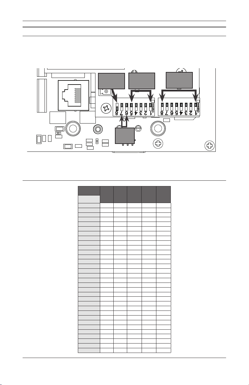
CONFIGURATION
All microphone station operational functions are configured in the announcement controller software. You must correctly
set the DIP switches on the microphone station so that it is correctly addressed on the network in order to communicate
with the announcement controller. Refer to Figure 8 for the DIP switch functions. The DIP switches use binary encoding
with DIP switch 1 referencing the least significant bit (LSB). Tables have been provided containing the correct switch
combinations for each available group and mic number.
+
–
S
Group
Address
Mic
Number
Not
Used
Line Out
Enable
Figure 8 - 524 DIP Switch Locations
Group DIP Switch Settings
Switch 1 2 3 4 5
Group
1 ON OFF OFF OFF OFF
2 OFF ON OFF OFF OFF
3 ON ON OFF OFF OFF
4 OFF OFF ON OFF OFF
5 ON OFF ON OFF OFF
6 OFF ON ON OFF OFF
7 ON ON ON OFF OFF
8 OFF OFF OFF ON OFF
9 ON OFF OFF ON OFF
10 OFF ON OFF ON OFF
11 ON ON OFF ON OFF
12 OFF OFF ON ON OFF
13 ON OFF ON ON OFF
14 OFF ON ON ON OFF
15 ON ON ON ON OFF
16 OFF OFF OFF OFF ON
17 ON OFF OFF OFF ON
18 OFF ON OFF OFF ON
19 ON ON OFF OFF ON
20 OFF OFF ON OFF ON
21 ON OFF ON OFF ON
22 OFF ON ON OFF ON
23 ON ON ON OFF ON
24 OFF OFF OFF ON ON
25 ON OFF OFF ON ON
26 OFF ON OFF ON ON
27 ON ON OFF ON ON
28 OFF OFF ON ON ON
29 ON OFF ON ON ON
30 OFF ON ON ON ON
31 ON ON ON ON ON
32 OFF OFF OFF OFF OFF

REV: 12-12 DOC: 374B PAGE 10
INSTALLATION INSTRUCTIONS IEDA524-H / IEDA520DTB DIGITAL MICROPHONE STATION
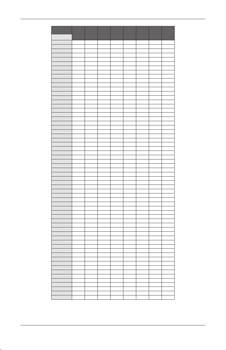
Mic Number DIP Switch Settings
Switch 1 2 3 4 5 6 7 8
Mic
1 ON OFF OFF OFF OFF OFF OFF OFF
2 OFF ON OFF OFF OFF OFF OFF OFF
3 ON ON OFF OFF OFF OFF OFF OFF
4 OFF OFF ON OFF OFF OFF OFF OFF
5 ON OFF ON OFF OFF OFF OFF OFF
6 OFF ON ON OFF OFF OFF OFF OFF
7 ON ON ON OFF OFF OFF OFF OFF
8 OFF OFF OFF ON OFF OFF OFF OFF
9 ON OFF OFF ON OFF OFF OFF OFF
10 OFF ON OFF ON OFF OFF OFF OFF
11 ON ON OFF ON OFF OFF OFF OFF
12 OFF OFF ON ON OFF OFF OFF OFF
13 ON OFF ON ON OFF OFF OFF OFF
14 OFF ON ON ON OFF OFF OFF OFF
15 ON ON ON ON OFF OFF OFF OFF
16 OFF OFF OFF OFF ON OFF OFF OFF
17 ON OFF OFF OFF ON OFF OFF OFF
18 OFF ON OFF OFF ON OFF OFF OFF
19 ON ON OFF OFF ON OFF OFF OFF
20 OFF OFF ON OFF ON OFF OFF OFF
21 ON OFF ON OFF ON OFF OFF OFF
22 OFF ON ON OFF ON OFF OFF OFF
23 ON ON ON OFF ON OFF OFF OFF
24 OFF OFF OFF ON ON OFF OFF OFF
25 ON OFF OFF ON ON OFF OFF OFF
26 OFF ON OFF ON ON OFF OFF OFF
27 ON ON OFF ON ON OFF OFF OFF
28 OFF OFF ON ON ON OFF OFF OFF
29 ON OFF ON ON ON OFF OFF OFF
30 OFF ON ON ON ON OFF OFF OFF
31 ON ON ON ON ON OFF OFF OFF
32 OFF OFF OFF OFF OFF ON OFF OFF
33 ON OFF OFF OFF OFF ON OFF OFF
34 OFF ON OFF OFF OFF ON OFF OFF
35 ON ON OFF OFF OFF ON OFF OFF
36 OFF OFF ON OFF OFF ON OFF OFF
37 ON OFF ON OFF OFF ON OFF OFF
38 OFF ON ON OFF OFF ON OFF OFF
39 ON ON ON OFF OFF ON OFF OFF
40 OFF OFF OFF ON OFF ON OFF OFF
41 ON OFF OFF ON OFF ON OFF OFF
42 OFF ON OFF ON OFF ON OFF OFF
43 ON ON OFF ON OFF ON OFF OFF
44 OFF OFF ON ON OFF ON OFF OFF
45 ON OFF ON ON OFF ON OFF OFF
46 OFF ON ON ON OFF ON OFF OFF
47 ON ON ON ON OFF ON OFF OFF
48 OFF OFF OFF OFF ON ON OFF OFF
49 ON OFF OFF OFF ON ON OFF OFF
50 OFF ON OFF OFF ON ON OFF OFF
51 ON ON OFF OFF ON ON OFF OFF
52 OFF OFF ON OFF ON ON OFF OFF
53 ON OFF ON OFF ON ON OFF OFF
54 OFF ON ON OFF ON ON OFF OFF
55 ON ON ON OFF ON ON OFF OFF
56 OFF OFF OFF ON ON ON OFF OFF
57 ON OFF OFF ON ON ON OFF OFF
58 OFF ON OFF ON ON ON OFF OFF
59 ON ON OFF ON ON ON OFF OFF
60 OFF OFF ON ON ON ON OFF OFF
61 ON OFF ON ON ON ON OFF OFF
62 OFF ON ON ON ON ON OFF OFF
63 ON ON ON ON ON ON OFF OFF

PAGE 11 DOC: 374B REV: 12-12
IEDA524-H / IEDA520DTB DIGITAL MICROPHONE STATION INSTALLATION INSTRUCTIONS
Switch 1 2 3 4 5 6 7 8
Mic
64 OFF OFF OFF OFF OFF OFF ON OFF
65 ON OFF OFF OFF OFF OFF ON OFF
66 OFF ON OFF OFF OFF OFF ON OFF
67 ON ON OFF OFF OFF OFF ON OFF
68 OFF OFF ON OFF OFF OFF ON OFF
69 ON OFF ON OFF OFF OFF ON OFF
70 OFF ON ON OFF OFF OFF ON OFF
71 ON ON ON OFF OFF OFF ON OFF
72 OFF OFF OFF ON OFF OFF ON OFF
73 ON OFF OFF ON OFF OFF ON OFF
74 OFF ON OFF ON OFF OFF ON OFF
75 ON ON OFF ON OFF OFF ON OFF
76 OFF OFF ON ON OFF OFF ON OFF
77 ON OFF ON ON OFF OFF ON OFF
78 OFF ON ON ON OFF OFF ON OFF
79 ON ON ON ON OFF OFF ON OFF
80 OFF OFF OFF OFF ON OFF ON OFF
81 ON OFF OFF OFF ON OFF ON OFF
82 OFF ON OFF OFF ON OFF ON OFF
83 ON ON OFF OFF ON OFF ON OFF
84 OFF OFF ON OFF ON OFF ON OFF
85 ON OFF ON OFF ON OFF ON OFF
86 OFF ON ON OFF ON OFF ON OFF
87 ON ON ON OFF ON OFF ON OFF
88 OFF OFF OFF ON ON OFF ON OFF
89 ON OFF OFF ON ON OFF ON OFF
90 OFF ON OFF ON ON OFF ON OFF
91 ON ON OFF ON ON OFF ON OFF
92 OFF OFF ON ON ON OFF ON OFF
93 ON OFF ON ON ON OFF ON OFF
94 OFF ON ON ON ON OFF ON OFF
95 ON ON ON ON ON OFF ON OFF
96 OFF OFF OFF OFF OFF ON ON OFF
97 ON OFF OFF OFF OFF ON ON OFF
98 OFF ON OFF OFF OFF ON ON OFF
99 ON ON OFF OFF OFF ON ON OFF
100 OFF OFF ON OFF OFF ON ON OFF
101 ON OFF ON OFF OFF ON ON OFF
102 OFF ON ON OFF OFF ON ON OFF
103 ON ON ON OFF OFF ON ON OFF
104 OFF OFF OFF ON OFF ON ON OFF
105 ON OFF OFF ON OFF ON ON OFF
106 OFF ON OFF ON OFF ON ON OFF
107 ON ON OFF ON OFF ON ON OFF
108 OFF OFF ON ON OFF ON ON OFF
109 ON OFF ON ON OFF ON ON OFF
110 OFF ON ON ON OFF ON ON OFF
111 ON ON ON ON OFF ON ON OFF
112 OFF OFF OFF OFF ON ON ON OFF
113 ON OFF OFF OFF ON ON ON OFF
114 OFF ON OFF OFF ON ON ON OFF
115 ON ON OFF OFF ON ON ON OFF
116 OFF OFF ON OFF ON ON ON OFF
117 ON OFF ON OFF ON ON ON OFF
118 OFF ON ON OFF ON ON ON OFF
119 ON ON ON OFF ON ON ON OFF
120 OFF OFF OFF ON ON ON ON OFF
121 ON OFF OFF ON ON ON ON OFF
122 OFF ON OFF ON ON ON ON OFF
123 ON ON OFF ON ON ON ON OFF
124 OFF OFF ON ON ON ON ON OFF
125 ON OFF ON ON ON ON ON OFF
126 OFF ON ON ON ON ON ON OFF
127 ON ON ON ON ON ON ON OFF
128 OFF OFF OFF OFF OFF OFF OFF ON
129 ON OFF OFF OFF OFF OFF OFF ON

REV: 12-12 DOC: 374B PAGE 12
INSTALLATION INSTRUCTIONS IEDA524-H / IEDA520DTB DIGITAL MICROPHONE STATION
Switch 1 2 3 4 5 6 7 8
Mic
130 OFF ON OFF OFF OFF OFF OFF ON
131 ON ON OFF OFF OFF OFF OFF ON
132 OFF OFF ON OFF OFF OFF OFF ON
133 ON OFF ON OFF OFF OFF OFF ON
134 OFF ON ON OFF OFF OFF OFF ON
135 ON ON ON OFF OFF OFF OFF ON
136 OFF OFF OFF ON OFF OFF OFF ON
137 ON OFF OFF ON OFF OFF OFF ON
138 OFF ON OFF ON OFF OFF OFF ON
139 ON ON OFF ON OFF OFF OFF ON
140 OFF OFF ON ON OFF OFF OFF ON
141 ON OFF ON ON OFF OFF OFF ON
142 OFF ON ON ON OFF OFF OFF ON
143 ON ON ON ON OFF OFF OFF ON
144 OFF OFF OFF OFF ON OFF OFF ON
145 ON OFF OFF OFF ON OFF OFF ON
146 OFF ON OFF OFF ON OFF OFF ON
147 ON ON OFF OFF ON OFF OFF ON
148 OFF OFF ON OFF ON OFF OFF ON
149 ON OFF ON OFF ON OFF OFF ON
150 OFF ON ON OFF ON OFF OFF ON
151 ON ON ON OFF ON OFF OFF ON
152 OFF OFF OFF ON ON OFF OFF ON
153 ON OFF OFF ON ON OFF OFF ON
154 OFF ON OFF ON ON OFF OFF ON
155 ON ON OFF ON ON OFF OFF ON
156 OFF OFF ON ON ON OFF OFF ON
157 ON OFF ON ON ON OFF OFF ON
158 OFF ON ON ON ON OFF OFF ON
159 ON ON ON ON ON OFF OFF ON
160 OFF OFF OFF OFF OFF ON OFF ON
161 ON OFF OFF OFF OFF ON OFF ON
162 OFF ON OFF OFF OFF ON OFF ON
163 ON ON OFF OFF OFF ON OFF ON
164 OFF OFF ON OFF OFF ON OFF ON
165 ON OFF ON OFF OFF ON OFF ON
166 OFF ON ON OFF OFF ON OFF ON
167 ON ON ON OFF OFF ON OFF ON
168 OFF OFF OFF ON OFF ON OFF ON
169 ON OFF OFF ON OFF ON OFF ON
170 OFF ON OFF ON OFF ON OFF ON
171 ON ON OFF ON OFF ON OFF ON
172 OFF OFF ON ON OFF ON OFF ON
173 ON OFF ON ON OFF ON OFF ON
174 OFF ON ON ON OFF ON OFF ON
175 ON ON ON ON OFF ON OFF ON
176 OFF OFF OFF OFF ON ON OFF ON
177 ON OFF OFF OFF ON ON OFF ON
178 OFF ON OFF OFF ON ON OFF ON
179 ON ON OFF OFF ON ON OFF ON
180 OFF OFF ON OFF ON ON OFF ON
181 ON OFF ON OFF ON ON OFF ON
182 OFF ON ON OFF ON ON OFF ON
183 ON ON ON OFF ON ON OFF ON
184 OFF OFF OFF ON ON ON OFF ON
185 ON OFF OFF ON ON ON OFF ON
186 OFF ON OFF ON ON ON OFF ON
187 ON ON OFF ON ON ON OFF ON
188 OFF OFF ON ON ON ON OFF ON
189 ON OFF ON ON ON ON OFF ON
190 OFF ON ON ON ON ON OFF ON
191 ON ON ON ON ON ON OFF ON
192 OFF OFF OFF OFF OFF OFF ON ON
193 ON OFF OFF OFF OFF OFF ON ON
194 OFF ON OFF OFF OFF OFF ON ON
195 ON ON OFF OFF OFF OFF ON ON
PAGE 13 DOC: 374B REV: 12-12
IEDA524-H / IEDA520DTB DIGITAL MICROPHONE STATION INSTALLATION INSTRUCTIONS
Switch 1 2 3 4 5 6 7 8
Mic
196 OFF OFF ON OFF OFF OFF ON ON
197 ON OFF ON OFF OFF OFF ON ON
198 OFF ON ON OFF OFF OFF ON ON
199 ON ON ON OFF OFF OFF ON ON
200 OFF OFF OFF ON OFF OFF ON ON
201 ON OFF OFF ON OFF OFF ON ON
202 OFF ON OFF ON OFF OFF ON ON
203 ON ON OFF ON OFF OFF ON ON
204 OFF OFF ON ON OFF OFF ON ON
205 ON OFF ON ON OFF OFF ON ON
206 OFF ON ON ON OFF OFF ON ON
207 ON ON ON ON OFF OFF ON ON
208 OFF OFF OFF OFF ON OFF ON ON
209 ON OFF OFF OFF ON OFF ON ON
210 OFF ON OFF OFF ON OFF ON ON
211 ON ON OFF OFF ON OFF ON ON
212 OFF OFF ON OFF ON OFF ON ON
213 ON OFF ON OFF ON OFF ON ON
214 OFF ON ON OFF ON OFF ON ON
215 ON ON ON OFF ON OFF ON ON
216 OFF OFF OFF ON ON OFF ON ON
217 ON OFF OFF ON ON OFF ON ON
218 OFF ON OFF ON ON OFF ON ON
219 ON ON OFF ON ON OFF ON ON
220 OFF OFF ON ON ON OFF ON ON
221 ON OFF ON ON ON OFF ON ON
222 OFF ON ON ON ON OFF ON ON
223 ON ON ON ON ON OFF ON ON
224 OFF OFF OFF OFF OFF ON ON ON
225 ON OFF OFF OFF OFF ON ON ON
226 OFF ON OFF OFF OFF ON ON ON
227 ON ON OFF OFF OFF ON ON ON
228 OFF OFF ON OFF OFF ON ON ON
229 ON OFF ON OFF OFF ON ON ON
230 OFF ON ON OFF OFF ON ON ON
231 ON ON ON OFF OFF ON ON ON
232 OFF OFF OFF ON OFF ON ON ON
233 ON OFF OFF ON OFF ON ON ON
234 OFF ON OFF ON OFF ON ON ON
235 ON ON OFF ON OFF ON ON ON
236 OFF OFF ON ON OFF ON ON ON
237 ON OFF ON ON OFF ON ON ON
238 OFF ON ON ON OFF ON ON ON
239 ON ON ON ON OFF ON ON ON
240 OFF OFF OFF OFF ON ON ON ON
241 ON OFF OFF OFF ON ON ON ON
242 OFF ON OFF OFF ON ON ON ON
243 ON ON OFF OFF ON ON ON ON
244 OFF OFF ON OFF ON ON ON ON
245 ON OFF ON OFF ON ON ON ON
246 OFF ON ON OFF ON ON ON ON
247 ON ON ON OFF ON ON ON ON
248 OFF OFF OFF ON ON ON ON ON
249 ON OFF OFF ON ON ON ON ON
250 OFF ON OFF ON ON ON ON ON
251 ON ON OFF ON ON ON ON ON
252 OFF OFF ON ON ON ON ON ON
253 ON OFF ON ON ON ON ON ON
254 OFF ON ON ON ON ON ON ON
255 ON ON ON ON ON ON ON ON
256 OFF OFF OFF OFF OFF OFF OFF OFF
NOTE: The maximum total number of microphone stations supported in GLOBALCOM is 240.

REV: 12-12 DOC: 374B PAGE 14
INSTALLATION INSTRUCTIONS IEDA524-H / IEDA520DTB DIGITAL MICROPHONE STATION
Line Level Audio Output Enable
Switch 8
Line Output Enabled ON
Line Output Disabled OFF
DIMENSIONS
4.952”
4.952”
1.812”
3.281”
1.907”
.900”
.750”
Figure 9 - IEDA524-H
5.128”
5.318”
5.662”
Figure 10 - IEDA524-H with optional IEDA520DTB

REV: 12-12 DOC: 374B ©2012, Innovative Electronic Designs, LLC
Innovative Electronic Designs, LLC +1.502.267.7436 phone
9701 Taylorsville Road +1.502.267.9070 fax
Louisville, KY 40299, USA www.iedaudio.com
INSTALLATION INSTRUCTIONS IEDA524-H / IEDA520DTB DIGITAL MICROPHONE STATION
This manual suits for next models
1
Table of contents
Other IED Microphone manuals


