IED LC372M User manual

REV: 03-11 DOC1309B PAGE 1
INSTALLATION INSTRUCTIONS LC372M REMOTE MICROPHONE MODULE
LC372M REMOTE
MICROPHONE MODULE
Installation Instructions
INTRODUCTION
The LC372M remote microphone is an optional component of the IED LANcom SCS system for use with the LC372SR
communications module. This microphone unit is for remote use in classrooms for intercom.
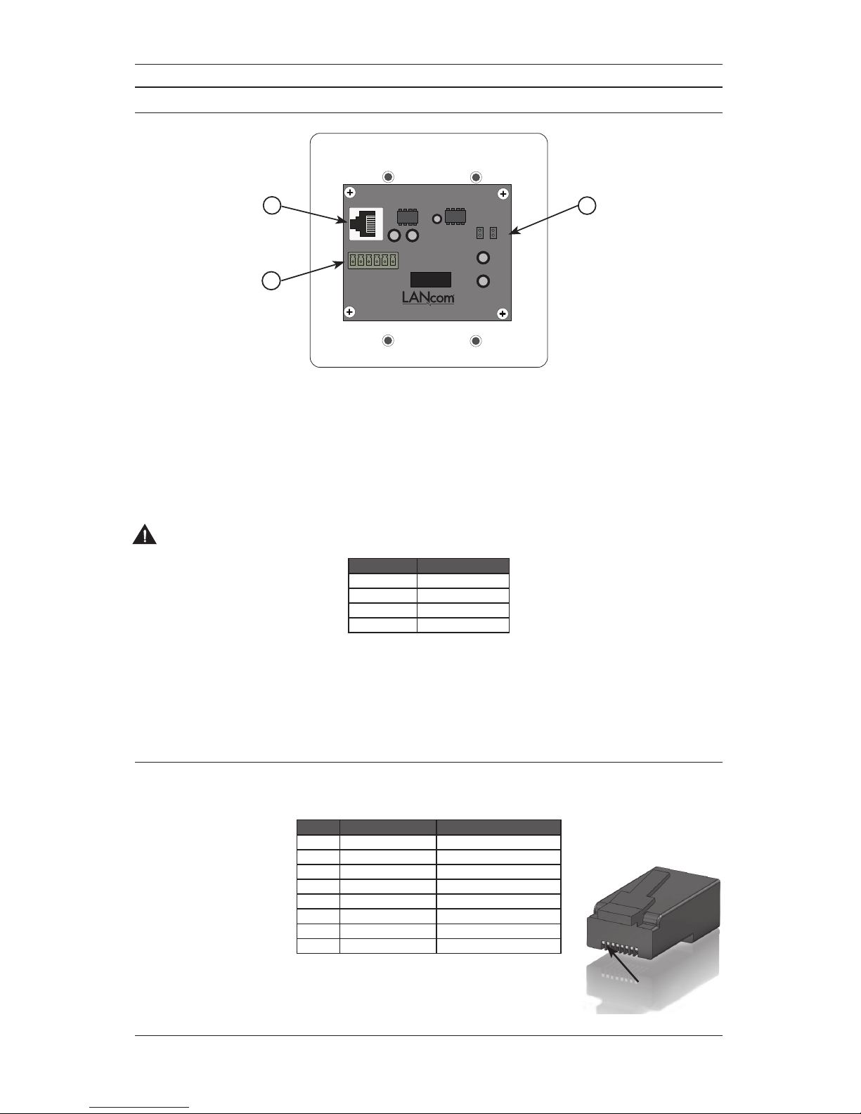
Figure 1 - LC372M Front View
IMPORTANT SAFETY INSTRUCTIONS
1. Read these instructions.
2. Keep these instructions.
3. Heed all warnings.
4. Follow all instructions.
5. Do not use this apparatus near water.
6. Clean only with dry cloth.
7. Install in accordance with the manufacturer’s in-
structions.
8. Do not install near any heat sources such as ra-
diators, heat registers, stoves, or other apparatus
(including amplifiers) that produce heat.
9. Only use attachments/accessories specified by the
manufacturer.
10. Refer all servicing to qualified service personnel.
Servicing is required when the apparatus has been
damaged in any way, such as power-supply cord
or plug is damaged, liquid has been spilled or ob-
jects have fallen into the apparatus, the apparatus
has been exposed to rain or moisture, does not
operate normally, or has been dropped.
SAFETY SYMBOLS
Labeling on products and the Installation Instructions &
User Manual may use safety related graphical symbols
as shown below to note safety requirements.
Lightning Bolt: The lightning flash with
arrowhead symbol, within an equilateral triangle,
WARNING symbol, is intended to alert the user to
the presence of un-insulated dangerous voltage
within the product’s enclosure that may be
sufficient in magnitude to constitute a risk of
electric shock to persons or domestic animals.
Exclamation Point: The exclamation point
within an equilateral triangle, CAUTION symbol,
is in-tended to alert the user to the presence of
important operating and maintenance (servicing)
instructions, or a hazard that can damage equip-
ment.
Do not proceed beyond a WARNING or CAUTION notice
until you have understood the hazardous condition and
have taken appropriate steps.
PAGE 2 DOC1309B REV: 03-11
LC372M REMOTE MICROPHONE MODULE INSTALLATION INSTRUCTIONS
CONNECTIONS
PIN 3
P IN 4
P IN 5
P IN 6
GND
+48V
NO SHU NT = 6 dB GAI N
50d B
26d B
J2
J1
3
12
Figure 2 - LC372M Rear View
1. Output RJ45 Connector
This connector is used to send the audio from the microphone and any third-party pushbutton call switches to an
LC372SR or LC331IC. See Table 2 for the connector wiring details.
2. Gain Selection Jumpers
These jumpers are used to adjust the microphone gain. Use higher gain settings when the microphone is not
picking up intercom calls in the room.
CAUTION – Do not place shunts on both J1 and J2 at the same time. Doing so may result in damage to the
equipment.
Pin Function
No Shunt 6 dB of gain
J1 26 dB of gain
J2 50 dB of gain
J1+J2 Not Allowed
Table 1 - Gain Jumper Settings
3. Auxilliary Connector
This connector provides termination points when using pushbutton call switches from other manufacturers. A mo-
nentary switch can be wired to one of the four available control lines and ground. A voltage test point (+48VDC) is
provided as an aid in troubleshooting. Refer to Figure 3 for wiring instructions.
RJ45 Connector Wiring
Each unit connects to either an LC372SR Sound Reinforcement Module or LC331IC Integrated Communications Module
using CAT5 or better structured cable. Each connector should be wired as shown in Table 2.
Pin Function Cat5 Color Code
1 Audio + Orange /W
2 Audio - Orange
3 Switch out Green /W
4 Switch out Blue
5 Switch out Blue/W
6 Switch out Green
7 +48 VDC Brown /W
8 Ground Brown
Table 2 - RJ45 Connector Wiring
PIN 1
REV: 03-11 DOC1309B PAGE 3
INSTALLATION INSTRUCTIONS LC372M REMOTE MICROPHONE MODULE
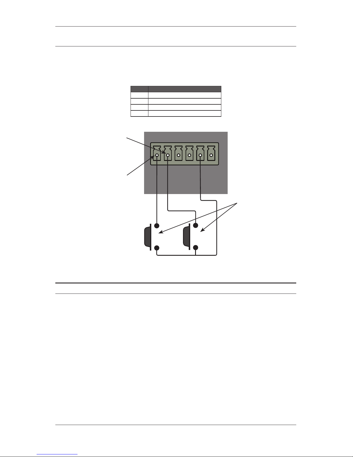
Control Pin Functions
The Auxilliary Connector allows a remote pushbutton switch manufactured by others to be used as a remote call switch
in the system. Each switch must be wired to one of the four available control lines. Multiple buttons can be connected to
the same control line when necessary. The function of each control line is listed in Table 3. The functions may be globally
modified in the LANcom SCS software. Control line 6 is configured in software to perform actions such as closing a relay
that can be used to raise and lower a projection screen or blinds.
Pin Function
3 Normal intercom call request
4 Emergency intercom call request
5 Lockdown acknowledgement
6 Software-configurable action
Table 3 - Control Pin Functions
PIN 3
P IN 4
P IN 5
P IN 6
GND
+48V
NO SHUNT = 6 dB GAIN
50d B
26d B
J2
J1
Pushbutton
Switches
Wired to make
normal intercom call
requests
Wired to make
emergency intercom
call requests
Figure 3 - Pushbutton Switch Wiring
Specifications
Mechanical
Dimensions ...................................................... 4.5” W x 4.5” H x 1.06” D (114.3mm W x 114.3mm H x 27mm D)
Projection in Front of Plate ............................................................................................................ 0.013” (32mm)
Mounting Depth ............................................................................................................................. 1.00” (25.4mm)
Mounting Box ..............................................................................................................................2-Gang Deep Box
Recommended Electrical Box .......................... Steel City 52151-1/2-3/4 (4” x 4” Box) with 53151-1/2 Extension
Electrical
Power ...........................................................................................................................................48VDC, 12.5 mA
Max. Audio Output .....................................................................................................................................+27dBu
THD .................................................................................................................................................<= 0.0033%
Frequency Response ............................................................................... -3dB @ 75Hz – 10kHz, -20dB @ 20kHz
Gain (Jumper Selectable) ...................................................................................... +52.7dB, +27.5dB or +6.6dB
S/N @ 53dB gain (+24dBu output) .............................................................................................................. 89dB
S/N @ 26dB gain (+24dBu output) ............................................................................................................. 110dB
S/N @ 6dB gain (+24dBu output) ............................................................................................................... 120dB
Connectors
Power and Audio Out...................................................................................................................................... RJ45
Connects to LC372SR or LC331IC using CAT5 or better
** Do not use an RJ45 boot in the box at the module end **
REV: 03-11 DOC1309B ©2011, Innovative Electronic Designs, LLC
Innovative Electronic Designs, LLC +1.502.267.7436 phone
9701 Taylorsville Road +1.502.267.9070 fax
Louisville, KY 40299, USA www.iedaudio.com
INSTALLATION INSTRUCTIONS LC372M REMOTE MICROPHONE MODULE
PIN 3
P IN 4
P IN 5
P IN 6
GND
+48V
NO SHU NT = 6 dB GAIN
50d B
26d B
J2
J1
PIN 3
P IN 4
P IN 5
P IN 6
GND
+48V
NO SHU NT = 6 dB GAIN
50d B
26d B
J2
J1
AUX AUDIO INPUT
+- S +- S + - S +-V
M
SPKR
OUT
LINE
OUT MUTEPOWER FORM C RELAY OUTPUTS
NC NOC NC NOC NC NOC NC NOC
ETH ERNET/
IED MIDSPAN
Model# LANcom LC372SR
HAN DSET
INTERFACE
AUX
INPUT
CALL SWIT CHES
REMOTE MIC
IR RECEIVER INPUTS
PIN6
PIN5
PIN4
PIN3
PIN6
PIN5
PIN4
PIN3
OUTPUT INPUT
PB2
PB1
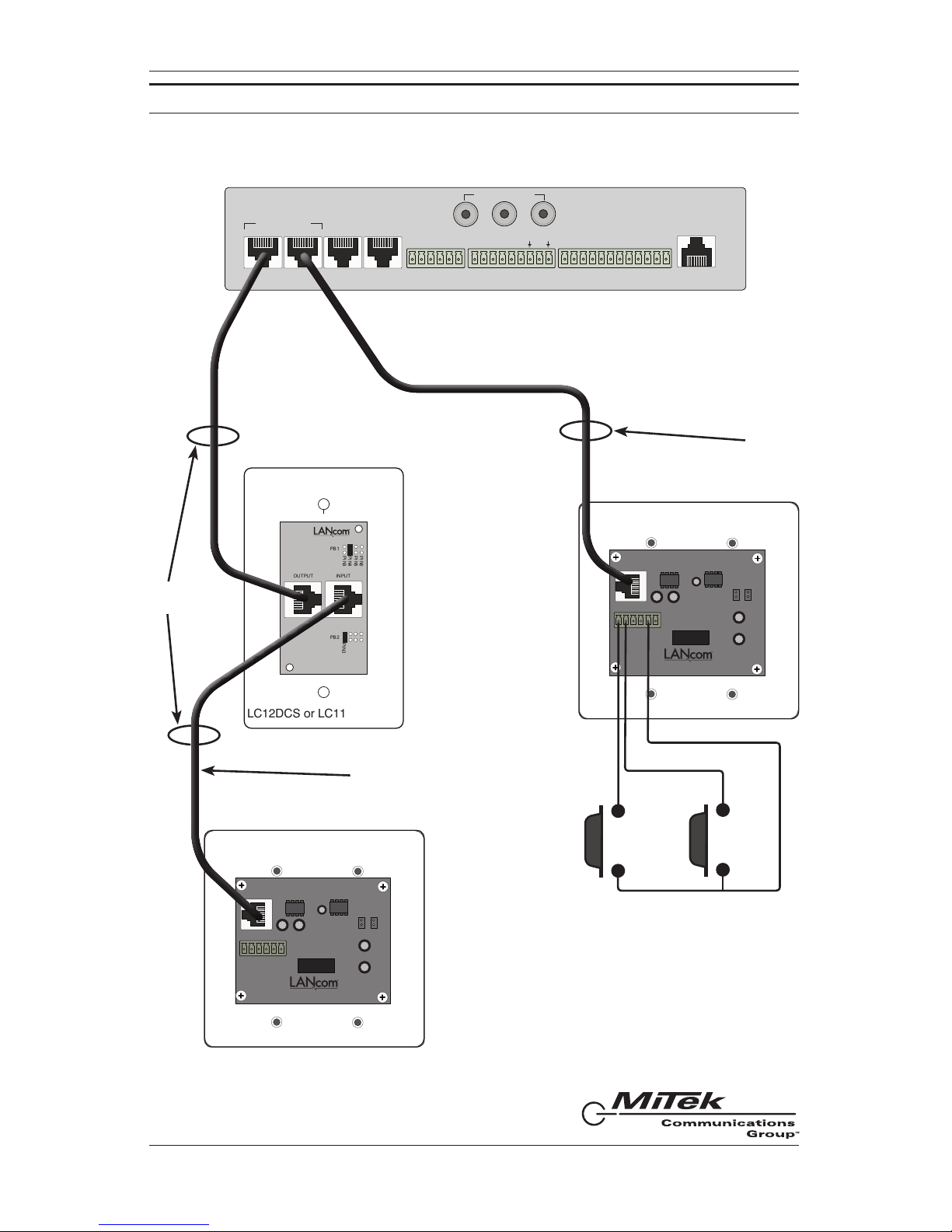
LC12DCS or LC11CS
LC372SR (shown) or LC331IC
LC372M
LC372M
Category 5
Cable
Category 5
Cable
The LC372M is daisy-chained
through the LC12DCS or LC11CS
Pushbutton switches by other
manufacturers
CONNECTION DIAGRAM
Table of contents
Other IED Microphone manuals


