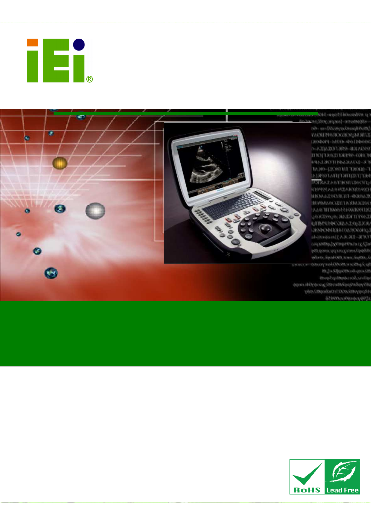
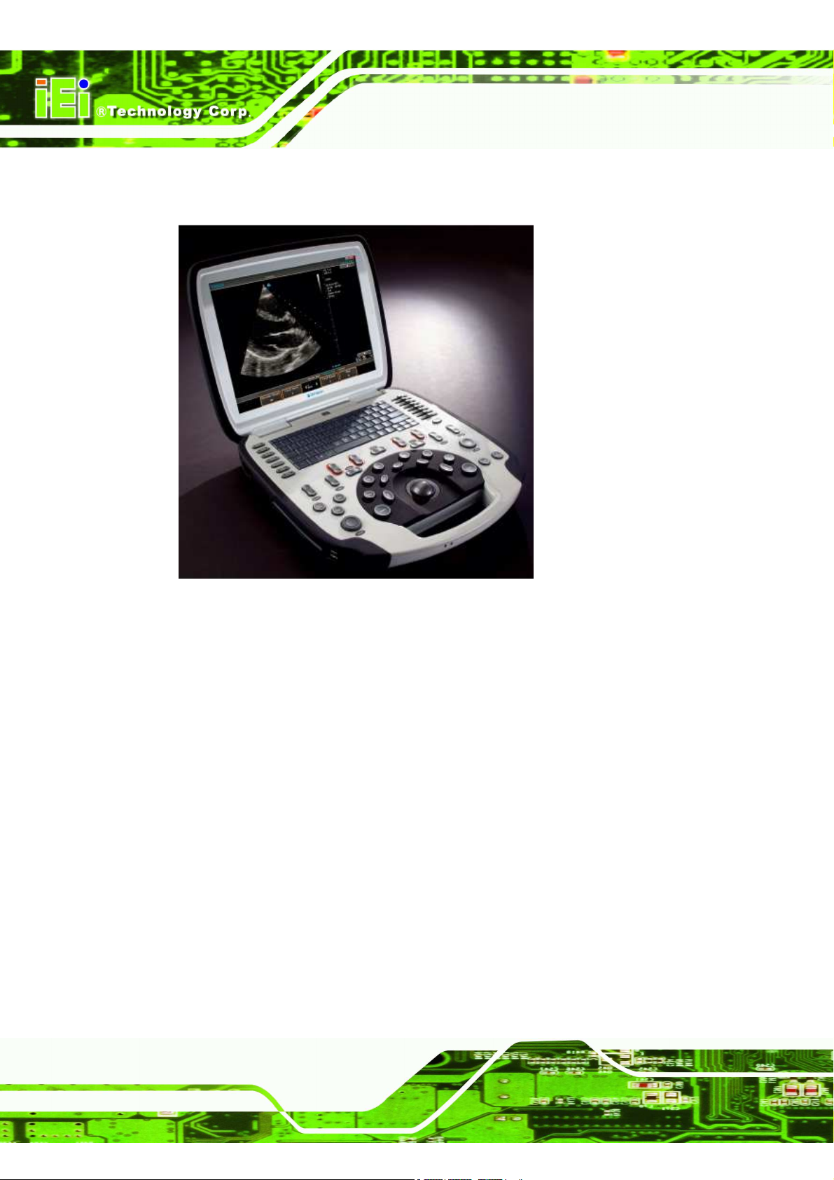
IEI Technology uSmart3400 User manual

uSmart3400
Page 1
IEI Technology Corp.
User Manual
Panel PC
MODEL:
uSmart3400
Rev. 1.01 – 22 October, 2013

uSmart3400
Page 2
Revision
Date Version
Changes
17 September, 2013
1.00 Initial release

uSmart3400
Page 3
Copyright
COPYRIGHT NOTICE
The information in this document is subject to change without prior notice in order
to improve reliability, design and function and does not represent a commitment on
the part of the manufacturer.
In no event will the manufacturer be liable for direct, indirect, special, incidental, or
consequential damages arising out of the use or inability to use the product or
documentation, even if advised of the possibility of such damages.
This document contains proprietary information protected by copyright. All rights
are reserved. No part of this manual may be reproduced by any mechanical,
electronic, or other means in any form without prior written permission of the
manufacturer.
TRADEMARKS
All registered trademarks and product names mentioned herein are used for
identification purposes only and may be trademarks and/or registered trademarks
of their respective owners.

uSmart3400
Page 4
Table of Contents
1. INTRODUCTION
………………………………………………………………...5
1.1 OVERVIEW……………………………………………………………………….6
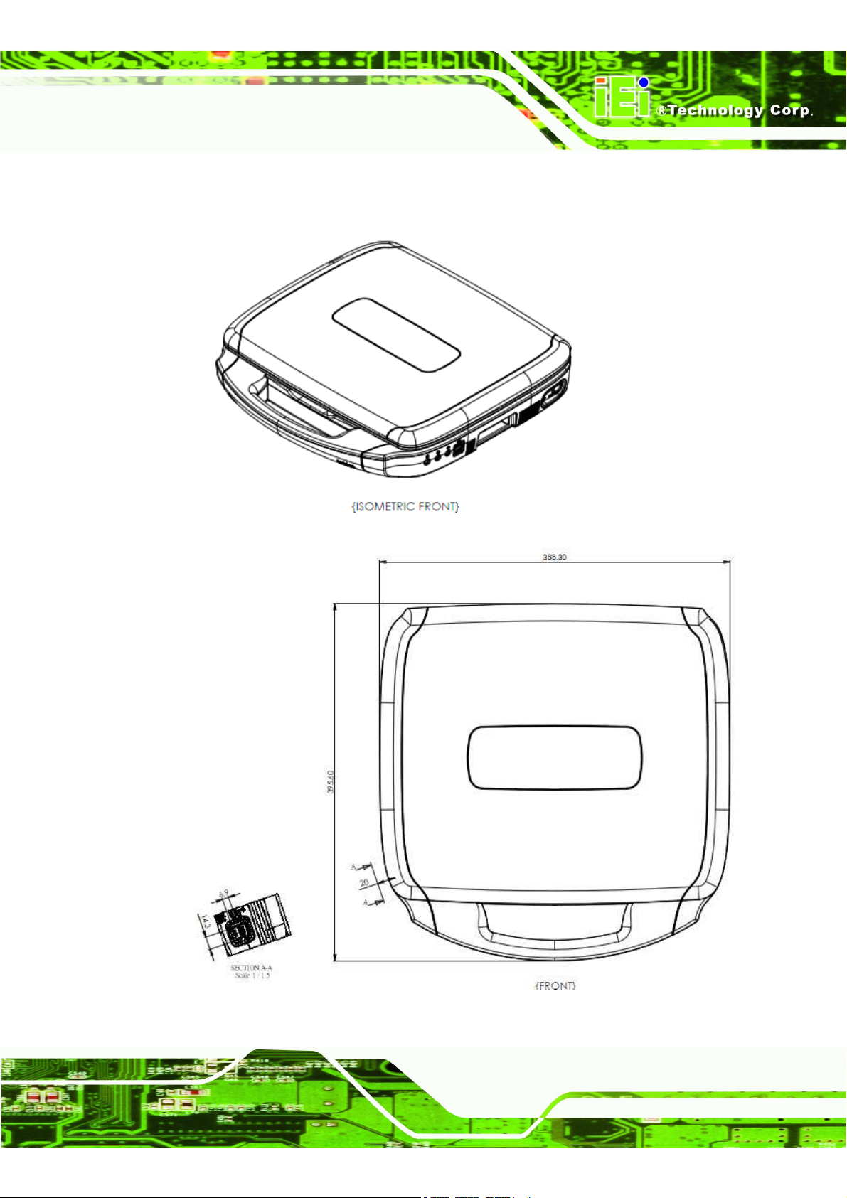
1.2 DIMENSIONS…………………………………….……………………………….7
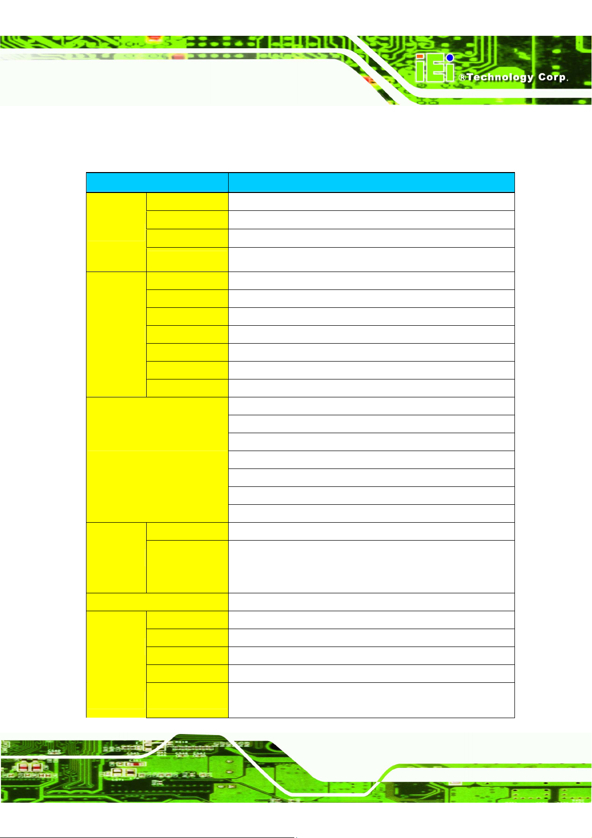
1.3 SPECIFICATIONS………………………………….…………………………….9
2 UNPACKING
………………………………………………………………………11
2.1 UNPACKING…………………………………………………………………….12
2.2 PACKING LIST………………………………………………………………….13
3 INSTALLATION
…………………………………………………………………14
3.1 ANTI-STATIC PRECAUTIONS…………….………………………………….15
3.2 INSTALLATION PRECAUTIONS…………………………………………….15
3.3 PREINSTALLED COMPONENTS…………………………………………….16
3.4 REMOVINGTHE BACK COVER……………………………………………..17
3.5 REMOVING THE CONSOLE………………………………………………….18
4 SYSTEM MAINTENANCE
……………………………………………………19
4.1 SYSTEM MAINTENANCE INTRODUCTION….……………………………20
4.2 MOTHERBOARD REPLACEMENT………………………………………….20
4.3 BACK COVER REMOVAL…………………………………………………….20
4.4 CONSOLE REPLACEMENT…………………………………………………..21
4.5 SO-DIMM REPLACEMENT…………………………………………………...21
5 SAFETY PRECAUTIONS
……………………………………………………...23
A.1 SAFETY PRECAUTIONS……………………………………….......…………24
A.1.1 General Safety Precautions………………………………………..………...24
A.1.2 Anti-static Precautions……………………………………………..………...25
A.1.3 Product Disposal ……………………………………………………………26
A.2 MAINTENANCE AND CLEANING PRECAUTIONS………………………26
A.2.1 Maintenance and Cleaning..…………………………………………………26
A.2.2 Cleaning Tools…………………………………………………………..…….27
A.2.3 Federal Communication Commission Interference Statement……………28
6 HAZARDOUS MATERIALS DISCLOSURE
…………………...........…...29
B.1 HAZARDOUS MATERIAL DISCLOSURE TABLE FOR IPB PRODUCTS
CERTIFIEDAS ROHS COMPLIANT UNDER 2002/95/EC WITHOUT
MERCURY…………………………………………………………………………...30

uSmart3400
Page 5
1 Introduction
Chapter
1

uSmart3400
Page 6
1.1 Overview
Figure 1-1: uSmart3400 Portable Computer
The uSmart3400 portable computer provides all the features of a PC. The
uSmart3400 provides wireless networking for integration into company/facility
networks. The major external device connections include USB 2.0 and serial port
connectors. Storage options include a 2.5” hard drive, allowing for flexibility in
choosing solid state drives or traditional hard drives. 2 HDMI outputs on the leftside
allows the uSmart3400 to connect to a second/third screen for duplicating the
screen contents or extending the user interface.

uSmart3400
Page 7
1.2 Dimensions

uSmart3400
Page 8
uSmart3400 Dimensions (mm)

uSmart3400
Page 9
1.3 Specifications
The technical specifications for the uSmart3400 system are listed in below table.
Model Name uSmart
martmart
mart3400
MB
SBC Model TRN-HM65-MB
CPU 2nd Generation Intel® Core™i7-3555LE processor
Chipset Intel HM65
RAM 2 x 4G DDR3 1333 SO-DIMM (Support ECC)
Display
LCD Size 15"
Max Resolution 1024x768
Brightness (cd/m2)
minimum of 300 nits
Contrast Ratio 500:1
LCD Color 16.2M
Pixel Pitch (mm) 0.297(H) x 0.297(V)
Viewing Angle (H-V)
170(H)/ 170(V)
I/O Port
1x Power DC-JACK Connector
1x RJ-45 Connector For LAN
4x USB2.0 port
2 x HDMI connector
1xExt Power Switch connector
1xLine in Jack connector
1x Line out Jack connector
LED
Sleep LED Blue
Charging LED
Bi-color, blue or amber. It is amber when
charging, and blue when fully charged and the power adapter is
connected.
Storage 1 x 2.5" 1T HDD
Main Module
DVD 1 x Slot-in DVD, 8x SuperDrive DVD +/‐R DL/DVD +/‐RW, CD‐RW
WiFi 1 x Wireless LAN 802.11/b/g/n module by internal Mini PCIe interface
Speaker 2 x stereo speakers + 1 x sub‐woofer (internal speaker)
Console 1 x Keyboard/Trackball Console
Camera module Up to UXGA resolution (1600X1200) to take still image, support VGA
(640x480) resolution up to 30fps at YUY2 mode

uSmart3400
Page 10
Physical
Construction
Material PC+ABS
Dimension (WxHxD)
388.3*395.6*88.45 (mm)
Weight 6.8kg
Magnetic Latch
a. Magnet size:30mm x 8mm x 6mm.
b. Q'ty : 8pcs (B part*4, C part *4)
c. Open/Close Force : 2.0kgf ~ 2.5kgf.
Environment
Operation
Temperature 0~35°C
Storage
Temperature 0~60°C
Power Battery SANYO UR18650FK, 11.1V, 5400mah, 3S2P=59.94WH
Power Supply Power adapter: medical grade AC/DC adapter, Output: 19 VDC
OS Windows 7 32bit
Others Logo Terason, illuminated logo
Flip-down feet

uSmart3400
Page 11
2 Unpacking
Chapter
2

uSmart3400
Page 12
2.1 Unpacking
To unpack the Portable Computer, follow the steps below:
WARNING!
The front side LCD screen has a protective plastic cover stuck to the
screen. Only remove the plastic cover after the panel PC has been
properly installed. This ensures the screen is protected during the
installation process.
Step 1: Use box cutters, a knife or a sharp pair of scissors that seals the top side
of the external (second) box.
Step 2: Open the external (second) box.
Step 3: Use box cutters, a knife or a sharp pair of scissors that seals the top side
of the internal (first) box.
Step 4: Lift the monitor out of the boxes.
Step 5: Remove both polystyrene ends, one from each side.
Step 6: Pull the plastic cover off the portable computer.
Step 7: Make sure all the components listed in the packing list are present. Step 0:

uSmart3400
Page 13
2.2 Packing List
The u Smart3400 is shipped with the following components:
Quantity
Item Remark
1 U Smart3400
1 EKG Cable
(P/N: TRN-32025-003200-100-C-RS)
1 Power Adapter
(P/N: TRN-63040-010120-020-RS)
Packing List
If any of the above items are missing or damaged, contact the distributor or sales
representative immediately.

uSmart3400
Page 14
3
Installation
Chapter
3

uSmart3400
Page 15
3.1 Anti-static Precautions
WARNING:
Failure to take ESD precautions during the maintenance may
result in permanent damage to the system and severe injury to the
user.
Electrostatic discharge (ESD) can cause serious damage to electronic components,
including the u Smart3400. Dry climates are especially susceptible to ESD. It is
therefore critical that whenever the u Smart3400 is accessed internally, or any other
electrical component is handled, the following anti-static precautions are strictly
adhered to.
Wear an anti-static wristband: - Wearing a simple anti-static wristband
can help to prevent ESD from damaging the board.
Self-grounding: - Before handling the board touch any grounded
conducting material. During the time the board is handled, frequently
touch any conducting materials that are connected to the ground.
Use an anti-static pad: - When configuring the u Smart3400, place it on
an antic-static pad. This reduces the possibility of ESD damaging the
uSmart3400.
Only handle the edges of the PCB: - When handling the PCB, hold the
PCB by the edges.
3.2 Installation Precautions
When installing the portable computer, please follow the precautions listed below:
Power turned off: When installing the portable computer, make sure the
power is off. Failing to turn off the power may cause severe injury to the
body and/or damage to the system.
Certified Engineers: Only certified engineers should install and modify
onboard functionalities.

uSmart3400
Page 16
Anti-static Discharge: If a user open the portable computer to configure
the jumpers or plug in added peripheral devices, ground themselves
first and wear and anti-static wristband.
3.3 Preinstalled Components
The following components are all preinstalled.
Motherboard
DDR3 memory module
TFT LCD
System cooling fans
CPU
HDD
Wi-Fi module
Optical disk drive

uSmart3400
Page 17
3.4 Removing the Back Cover
Remove all the retention screws on the back cover. Lift the cover up to remove.

uSmart3400
Page 18
3.5 Removing the Console
Remove all the retention screws on the chassis base. Lift the console up to remove.

uSmart3400
Page 19
Chapter
4
4 System Maintenance

uSmart3400
Page 20
4.1 System Maintenance Introduction
The following system components may require maintenance.
Motherboard
SO-DIMM module
Wifi module
Cooling fans
HDD
If these components fail, they must be replaced. Please contact the system reseller
or vendor to purchase replacement parts. Replacement instructions for the above
listed components are described below.
4.2 Motherboard Replacement
A user cannot replace a motherboard. If the motherboard fails it must be shipped
back to IEI to be replaced. If the system motherboard has failed, please contact the
system vendor, reseller or an IEI sales person directly.
4.3 Back Cover Removal
WARNING!
Before removing the back cover, make sure all power to the
system has been disconnected. Failing to do so may cause severe
damage to the uSMART3400 and injury to the user.
To access the HDD and install ECG, ultrasound module, the back cover must be
removed. To remove the back cover, please refer to Section
599H
599H599H
599H
4 for removal
instructions.
Table of contents
Other IEI Technology Laptop manuals