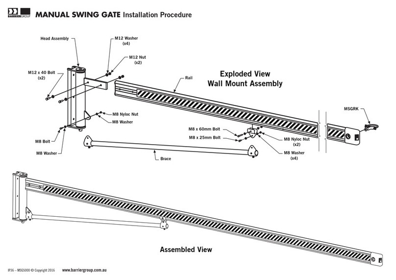
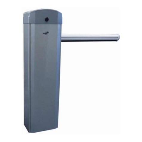
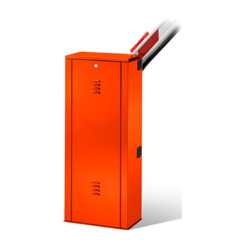
Ier Automatic Systems BL 32 User manual

The information contained in this document is the property of Automatic Systems and is confidential. The recipient shall
refrain from using it for any purpose other than the use of the products or the execution of the project to which it refers, and
from communicating it to third parties without Automatic Systems’ prior written agreement. Document subject to change
without notice.
BL3x-MT-EN-08 Page 1/59
BL 32 – BL 33
Automatic Systems
Wavre
OPERATING MANUAL
(translated from French)

The information contained in this document is the property of Automatic Systems and is confidential. The recipient shall refrain from using it for any purpose other than the use of the products or the
execution of the project to which it refers, and from communicating it to third parties without Automatic Systems’ prior written agreement. Document subject to change without notice.
BL3x-MT-EN-08 page 2/59
Revision page
Rev Date Written by Checked by Nature of the modification
02 Jan 25, 2007 MFy SD+JB - Replacement of D1 control board by AS1320 (version
3.6 of the program) => ch 4 added.
- Addition of reinforcement stop (ch. 6.6).
03 July 17, 2007 MFy - Update of the balance table (ch 6.5).
04 Nov. 09, 2007 MFy - Adapt to software version 4.1 of AS1320 control
board (ch 4).
- Addition of electric diagrams for options (ch 8).
- Update of the conformity certificates (ch 10).
05 Jun 18, 2008 MFy - Control board: adapted to version 6.x of the program.
- Revision of the electric diagram & addition of
connector blocks assignment.
06 July 3, 2008 MFy Ch.8.1: adapt the detection loops pinning references to
electric drawings (X9-X11-X13-X14).
07 2009-07-30 MFy Ch. 2.4: operation t° modification.
Ch. 10: EC certificate update.
08 2009-08-20 MFy "Safety warnings" chapter: add warning regarding the
use of the crank.

The information contained in this document is the property of Automatic Systems and is confidential. The recipient shall refrain from using it for any purpose other than the use of the products or the
execution of the project to which it refers, and from communicating it to third parties without Automatic Systems’ prior written agreement. Document subject to change without notice.
BL3x-MT-EN-08 page 3/59
Table of contents
1. SAFETY WARNINGS....................................................................................................................................4
2. GENERAL .....................................................................................................................................................5
2.1. General view .................................................................................................................................................5
2.2. Access to internal components......................................................................................................................6
2.3. Switching off the equipment ..........................................................................................................................8
2.4. General conditions of use..............................................................................................................................9
2.5. Emergency operation ....................................................................................................................................9
2.5.1. Opening or closing in case of power failure .....................................................................................9
2.5.2. In case of breakdown.....................................................................................................................10
3. SAMPLE CONFIGURATIONS ....................................................................................................................11
3.1. Example 1 ...................................................................................................................................................11
3.2. Example 2 ...................................................................................................................................................12
3.3. Example 3 ...................................................................................................................................................13
4. AS1320 Control board.................................................................................................................................14
4.1. “PRDSTD – BL_xxx” Menu: Diagnosis and monitoring ...............................................................................16
4.2. "QUICK START" menu: quick configuration................................................................................................22
5. INSTALLATION...........................................................................................................................................29
5.1. Preliminary work on site ..............................................................................................................................29
5.2. Handling and installing the unit....................................................................................................................30
5.3. Installing the lateral arm (BL32)...................................................................................................................31
5.4. Installing the central arm (BL32)..................................................................................................................32
5.5. Installing the oval arm (BL33)......................................................................................................................33
5.6. Fixing the shrouds (BL32 only)....................................................................................................................34
5.7. Dimensional views and arm segments ........................................................................................................35
5.8. Levelling the barrier arm..............................................................................................................................37
5.9. Installing the tip support ..............................................................................................................................38
5.9.1. Standard tip support ......................................................................................................................38
5.9.2. Electromagnetic tip support ...........................................................................................................39
5.10. Electrical connections and initial power-up..................................................................................................40
5.11. Check-list ....................................................................................................................................................40
5.12. Scrapping the equipment.............................................................................................................................40
6. ADJUSTMENTS AND TECHNICAL INTERVENTIONS ..............................................................................41
6.1. Arm balance adjustment..............................................................................................................................41
6.2. Belt tension adjustment ...............................................................................................................................42
6.2.1. Single belt (Fig. 25a) .....................................................................................................................43
6.2.2. Double belt (Fig. 25b) ....................................................................................................................43
6.3. Safety torque limiter adjustment ..................................................................................................................43
6.4. Limit switch adjustment ...............................................................................................................................44
6.5. Changing the arm model or the spring ........................................................................................................47
6.6. Adjustement of the reinforcement stop........................................................................................................50
7. MAINTENANCE ..........................................................................................................................................51
8. ELECTRICAL DRAWINGS .........................................................................................................................52
8.1. Control blocks assignment ..........................................................................................................................53
9. INSTALLATION PLANS ..............................................................................................................................56
10. EC conformity certificates............................................................................................................................59

The information contained in this document is the property of Automatic Systems and is confidential. The recipient shall refrain from using it for any purpose other than the use of the products or the
execution of the project to which it refers, and from communicating it to third parties without Automatic Systems’ prior written agreement. Document subject to change without notice.
BL3x-MT-EN-08 page 4/59
1. SAFETY WARNINGS
We thank you for having chosen the electrical rising barrier type BL32/BL33 designed and manufactured
by Automatic Systems. We are confident that your purchase will fully meet your requirements. However,
in order to obtain maximum satisfaction from this equipment for a maximum period of time, we strongly
advise you to read this manual carefully before installing the equipment.
Although this manual has been prepared with great care, some information may seem erroneous or
unclear to you. In this case, please do not hesitate to contact us with your remarks or questions.
WARNING:
YOUR RISING BARRIER TYPE BL32/BL33 COMPRISES A MECHANISM AND VARIOUS ELECTRICAL
COMPONENTS.ANY NEGLIGENCE DURING AN INTERVENTION IN THE MACHINE MAY SERIOUSLY
ENDANGER YOUR SAFETY.AS SOON AS YOU OPEN THE HOUSING,SWITCH OFF THE POWER BY
SWITCHING OFF THE MAIN CIRCUIT BREAKER (4:1)LOCATED BEHIND THE SIDE DOOR.BE CAREFUL IN
HANDLING ANY INTERNAL ELEMENT WHICH MIGHT BE UNDER POWER OR COULD BE SET IN MOTION.THE
HOOD SHOULD BE REMOVED ONLY IF YOU NEED TO REPLACE THE DRIVING SHAFT OR A SPRING,ADJUST
THE BELT(S)OR PROCEED WITH THE MAINTENANCE.
WARNING: Never raise the arm brackets by means of the crank, without the boom arm fixed for
counterbalancing the spring: the arm brakets would swing violently, with serious injury
risks for the operators.
IMPORTANT INFORMATION CONCERNING HEALTH & SAFETY PROCEDURES
The introduction of a pedestrian or vehicle barrier product as manufactured by Automatic Systems places a duty
of responsibility for the safety and well-being of any user(s) or person(s) in close proximity to such equipment.
You are required therefore to observe and put in place appropriate safety measures, as deemed necessary.
♦Pedestrian flow must be prohibited anywhere within a vehicle barrier passage-way, unless the movement of
the barrier system is clearly indicated, e.g. audible and/or visual signals, floor marking, notices, etc.
♦Access keys to any of the internal mechanisms can only be issued to authorised and qualified personnel,
aware of the relevant electrical and mechanical safety codes and regulations in force. All equipment housing
must be kept locked.
You have a legal obligation and responsibility to enforce good safety practices at all times. See also note below.
Note: In the countries of the European Union, the requirement 1.3.7.2 of the EC Machines Directive
prescribes that the pictogram for "Dangerous area* -- no entry for pedestrians" be affixed on both
sides of the equipment (* within 1 meter of the barrier arm in its closed position).
black
white
red

The information contained in this document is the property of Automatic Systems and is confidential. The recipient shall refrain from using it for any purpose other than the use of the products or the
execution of the project to which it refers, and from communicating it to third parties without Automatic Systems’ prior written agreement. Document subject to change without notice.
BL3x-MT-EN-08 page 5/59
2. GENERAL
2.1. General view
1:1 Side door
1:2 Safety lock with keys
1:3 Arm fixing jaw
1:4 Central arm bracket (BL32)
1:5 Central oval arm bracket (BL33)
1:6 Hood
1:7 Housing
1:8 Fixing braket
1:9 Heating resistance
1:10 Emergency crank handle
1:11 Automatic Systems logo

The information contained in this document is the property of Automatic Systems and is confidential. The recipient shall refrain from using it for any purpose other than the use of the products or the
execution of the project to which it refers, and from communicating it to third parties without Automatic Systems’ prior written agreement. Document subject to change without notice.
BL3x-MT-EN-08 page 6/59
2.2. Access to internal components
•Fig. 2 shows the internal components of the rising barrier type BL32/BL33 as you see them when you
remove the side door. Fig. 3 on next page shows most elements that will be referred to in this manual.
Please consult it whenever needed.
2:1 Motor
2:2 Torque limiter
2:3 Control board
2:4 Abutment
2:5 Drive belt
2:6 Emergency crank switch
2:7 Spring assembly
2:8 Limit switches
2:9 Ground connection
2:10 Identification plate

The information contained in this document is the property of Automatic Systems and is confidential. The recipient shall refrain from using it for any purpose other than the use of the products or the
execution of the project to which it refers, and from communicating it to third parties without Automatic Systems’ prior written agreement. Document subject to change without notice.
BL3x-MT-EN-08 page 7/59
Fig. 3
3:1
3:5
3:15
3:6
3:14
3:13
3:16
3:8
3:4
3:7
3:12
3:2
3:17
3:3 3:10
3:11
3:9
Légende:
3:1 Motor
3:2 Gear box
3:3 Motor control board
3:4 Abutment
3:5 Motor belt
3:6 Gear box belt
3:7 Springs
3:8 Limit switches
3:9 Arm-fixing jaw
3:10 Side door
3:11 Hood
3:12 Driving rod
3:13 Heater
3:14 Fixing brackets
3:15 Intermediate pulley
3:16 Fixing latches
3:17 Driving shaft

The information contained in this document is the property of Automatic Systems and is confidential. The recipient shall refrain from using it for any purpose other than the use of the products or the
execution of the project to which it refers, and from communicating it to third parties without Automatic Systems’ prior written agreement. Document subject to change without notice.
BL3x-MT-EN-08 page 8/59
2.3. Switching off the equipment
•As soon as you open the housing, switch off the power by switching off the main circuit breaker (4:1) located
behind the side door (1:1).
Fig. 4
4:1 Main circuit breaker
4:2 Ground terminal
4:2
4:1

The information contained in this document is the property of Automatic Systems and is confidential. The recipient shall refrain from using it for any purpose other than the use of the products or the
execution of the project to which it refers, and from communicating it to third parties without Automatic Systems’ prior written agreement. Document subject to change without notice.
BL3x-MT-EN-08 page 9/59
2.4. General conditions of use
•Your rising barrier type BL32/BL33 has been designed to operate in any kind of climatic environment, from
-35°C to +50°C (thanks to integrated heating resistance), with up to 95% of relative humidity.
2.5. Emergency operation
•The following instructions are to be given to the installation supervisor.
2.5.1. Opening or closing in case of power failure
-- Insert the emergency crank handle (1:10) into the crank hole (+ refer to "safety warnings" chapter!).
A safety device automatically switches off the power supply, thus eliminating any risk of accident in
case the power supply returns.
-- Turn the crank clockwise to open the barrier and counter-clockwise to close the barrier.
-- When the arm is in the horizontal or vertical position, keep turning the crank to lock the barrier
mechanically.

The information contained in this document is the property of Automatic Systems and is confidential. The recipient shall refrain from using it for any purpose other than the use of the products or the
execution of the project to which it refers, and from communicating it to third parties without Automatic Systems’ prior written agreement. Document subject to change without notice.
BL3x-MT-EN-08 page 10/59
2.5.2. In case of breakdown
Liquid crystal display is off
•Check the general power supply.
•Check the voltage on the circuit breaker (4:1), and
check if this late is on.
•Check the connection of the control wires referring
to the electrical diagram, as well as their tightening.
•Check the state of the fuses (1, p14) on the
electrical control board.
•Check that the green LEDs are lit on the logic
control board (6, p14).
- If not, check the general fuses (1, p14).
- If so, check that the logic board is not in
programming mode (cable RJ45, plugged in
socket 5, p14).
Liquid crystal display is on
•Check that the red LEDs (other than the analogue
output ones) on the logic control board are on (6,
p14).
- If not, cut the supply voltage and remove the
control terminal blocks (6, p14) (on the AS1320
and AS1321, if present). Turn the power back
on and then check whether the red LEDs are
on. If that is the case, there is a short circuit in
one of the control terminal blocks (6, p14). In
order to reactivate the outputs, the logic board
has to be turned on again.
- If so, refer to the displayed breakdowns
(“PRDSTD – BL_xxx“ menu Æ“Log”/”Close
Status”/”Open Status”).
The obstacle does not
move
Check the defects on the
frequency inverter
Refer to AS1320 control board manual.
The obstacle stops
during movement
OP, CL and STOP
commands have no effect.
Opening and/or closing limit switch is defective or
badly connected.
Note: If the trouble persists after you carry out the checks above, call your local Automatic Systems
agent.

The information contained in this document is the property of Automatic Systems and is confidential. The recipient shall refrain from using it for any purpose other than the use of the products or the
execution of the project to which it refers, and from communicating it to third parties without Automatic Systems’ prior written agreement. Document subject to change without notice.
BL3x-MT-EN-08 page 11/59
3. SAMPLE CONFIGURATIONS
3.1. Example 1
•The figure below shows an example of uni-directional access.
•The barrier is manually operated by the attendant via a three-push button box (Fig. 6b). The commands are:
opening, closing, stop.
•The equipment is controlled by a control board. For further information, please refer to p14.
Fig. 6
Entry
BL
This illustration applies to left-hand driving. For right-
hand driving, the configuration changes accordingly.
Fig. 6b

The information contained in this document is the property of Automatic Systems and is confidential. The recipient shall refrain from using it for any purpose other than the use of the products or the
execution of the project to which it refers, and from communicating it to third parties without Automatic Systems’ prior written agreement. Document subject to change without notice.
BL3x-MT-EN-08 page 12/59
3.2. Example 2
•The figure below shows an example of bi-directional access. The barrier opening is controlled in both
directions.
Fig. 7
Closing loop
Exit
BL
Entry
P
Opening loop
This illustration applies to left-hand driving. For right-
hand driving, the configuration changes accordingly.
•The barrier opening at entry is controlled by a peripheral P (e.g. a card reader) operated by a detection loop
embedded in the road surface. Opening the barrier is impossible if no vehicle is present on the loop, even
though a valid card is inserted in the reader.
•The opening manoeuvre at exit is manually operated by the attendant via a single-push button box.
•Closing and stop are automatically assured by the vehicle detection loop connected to the barrier and
embedded in the road surface under the arm boom.
•The equipment is controlled by the control board.
•For the exact model to install, as for the correct choice of loops to use (depending on the road width, etc.),
please refer to the corresponding technical data sheets or contact your local Automatic Systems agent.

The information contained in this document is the property of Automatic Systems and is confidential. The recipient shall refrain from using it for any purpose other than the use of the products or the
execution of the project to which it refers, and from communicating it to third parties without Automatic Systems’ prior written agreement. Document subject to change without notice.
BL3x-MT-EN-08 page 13/59
3.3. Example 3
•The figure below shows an example of bi-directional access. The barrier opening is controlled in one
direction, and automatic in the other.
Fig. 8
Closing loop
Exit
BL
Entry
Opening loop
POpening loop
This illustration applies to left-hand driving. For right-
hand driving, the configuration changes accordingly.
•The barrier opening at entry is automatically assured by a detection loop embedded in the road surface
upstream from the arm boom, connected to the barrier. Opening the barrier is impossible if no vehicle is
present on the entry loop.
•The barrier opening at exit is controlled by a peripheral (e.g. a token acceptor) operated by a detection loop
embedded in the road surface. Opening the barrier is impossible if no vehicle is present on the exit loop,
even though a valid token is inserted in the acceptor.
•Closing and stop are automatically assured by the vehicle detection loop connected to the barrier and
embedded in the road surface under the arm boom.
•The equipment is controlled by the control board.
•For the exact model to install, as for the correct choice of loops to use (depending on the road width, etc.),
please refer to the corresponding technical data sheets or contact your local Automatic Systems agent.

The information contained in this document is the property of Automatic Systems and is confidential. The recipient shall refrain from using it for any purpose other than the use of the products or the
execution of the project to which it refers, and from communicating it to third parties without Automatic Systems’ prior written agreement. Document subject to change without notice.
BL3x-MT-EN-08 page 14/59
4. AS1320 Control board
1. Fuses
2. Stabilised power supply indicator light
3. Menu display screen
4. Menu navigation keys
5. RJ45 communication connector
6. In/Out control connector blocks
7. 5 green LEDs (lit when the board is on)
8. Connectors for presence detectors (for inductive loops)
6
5
4
3
2
1
7
8

The information contained in this document is the property of Automatic Systems and is confidential. The recipient shall refrain from using it for any purpose other than the use of the products or the
execution of the project to which it refers, and from communicating it to third parties without Automatic Systems’ prior written agreement. Document subject to change without notice.
BL3x-MT-EN-08 page 15/59
The control board is the interface between the user and the barrier, which manages all the latter’s actions,
including any possible options.
Hereinafter are presented only the functions accessible in Simplified mode and sufficient for daily use of
the equipment.
For a detailed description of all the functions, their parameter setting, etc, please refer to the manual
dedicated to the board (available on request)..
Navigation in the menus of the display screen is based on a pull-down menu architecture on 3 levels:
MENUS ↔PARAMETERS ↔VALUES.
Moving from one level to another is achieved via the ◄►keys and navigation inside those levels by means of
the ▲▼keys (press for a few seconds to go from the at-rest screen to another menu).
Note: the second column in the tables below provides the parameter default values as they are entered during
manufacturing of the control board.
Nevertheless, as each equipment has been specifically adjusted in our workshops, the values actually present on
the board may differ slightly.
Menus are displayed in
capital letters on the top line,
starting with the first
character of the LCD.
Hold ▲or ▼for a few
seconds to leave the
PRDSTD screen and access
the other menus.
Only the first letter of each
word in the parameters is a
capital. They are displayed on
the top line starting with the
second character of the LCD
(i.e., there is a space in front).
At the end of the top line, the
parameter unit is displayed if
there is one.
A question mark (?) preceding the
parameter indicates that it is ready
to be modified.
The current value of the parameter
appears on the second line.
A star (*) below a parameter
indicates that it is the default value
(set in the factory).
To validate a modification, press the
OK key.
Store the modifications to
avoid them being lost in the event
of a power outage ("QUICK
START"
Æ
"MEMORY"
Æ
"Save")
OK
Menus Parameters
Arm Length
Barrier Type
Arm Type #
? Arm Length
* 3m00
? Arm Length
2m50
? Arm Length
2m00
? Arm Length
6m00
? Arm Length
3m50
? Arm Length
4m00
? Arm Length
4m50
? Arm Length
5m50
? Arm Length
5m00
CANCEL
VALIDATE
or
Values
QUICK START
DATE & TIME
CL REGULATION
PRDSTD - BL_xxx
TIMING
OUTPUT FUNCTION
SENSOR FUNCTION
OK

The information contained in this document is the property of Automatic Systems and is confidential. The recipient shall refrain from using it for any purpose other than the use of the products or the
execution of the project to which it refers, and from communicating it to third parties without Automatic Systems’ prior written agreement. Document subject to change without notice.
BL3x-MT-EN-08 page 16/59
4.1. “PRDSTD – BL_xxx” Menu: Diagnosis and monitoring
This screen appears when the unit is turned on and when there has not been any navigation through the menus in
Simplified mode for 100 seconds.
Parameter Values Description
OK key: (only within this menu (*) and when no other parameter
is selected): command for opening and closing the obstacle.
OK during opening: without effect.
OK during closing: inversion (= opening).
OK maintained: oscillating movement around the opening limit
switch: the obstacle opens, starts closing, opens again, etc.
(*) Warning: in "QUICKSTART" menu, validating passage from
Extended to Simplified menus through the OK key causes also
an opening or closing movement of the arm, even if a presence
is detected by the Presence sensors.
Note: When the operating mode is configured as “1 contact”
(see the “Exploitation” parameter in the "QUICK START” menu),
the obstacle closes automatically when the opening limit switch
is detected.
Left key (◄): Change the menu display language with each
touch.
EN = English
FR = Français
NL = Nederlands
DE = Deutsch
ES = Español
IT = Italiano
SV = Svenska
Select the language using the OK key or allow it to change
automatically after a few seconds, following which all of the
preceding parameter modifications (including the language)
will be saved in MEM1.
Soft. Version Display the software version used by the control unit, following
format "type – evolution – version – revision – minor index" of
the application.
The descriptions included in this chapter correspond to versions
"00-00-06-rr-00".
Program name
Date (DD/MM)
Time (hh:mm)
Choose a language
using the ◄button

The information contained in this document is the property of Automatic Systems and is confidential. The recipient shall refrain from using it for any purpose other than the use of the products or the
execution of the project to which it refers, and from communicating it to third parties without Automatic Systems’ prior written agreement. Document subject to change without notice.
BL3x-MT-EN-08 page 17/59
Log Display of the last 100 events (use ►the ▲and keys to view
preceding events).
For the first two seconds, the event number (00 for the last event
recorded (= most recent), 01 for the preceding event, and so
on), as well as the date (year-month-day) and time (hours-
minutes-seconds) of creation are displayed.
In the next two seconds, the event description is displayed.
For example:
2 s Log
00 060324 235034 On 24 March 2006 at 23 hours
(11 p.m.) 50 minutes and 34
seconds…
2 s Log
Out Of Service …the apparatus was put out of
service.
2 s Log
01 060324 235034
View the preceding message
(01) using the ►▲ keys…
2 s Log
Open Time Out
…we observe that it was put out
of service due to a time out
while opening.
Note: If no error message is displayed when the machine fails,
refer to the Troubleshooting chapter.
Power Up Power was turned on.
Power Down Power was turned off.
Short Circuit Short circuit of the control board outputs (connector blocks). The
short circuit is declared and the equipment put Out of Service
only after 3 unsuccessful reactivation tries within the 2.5 seconds
following a voltage drop in the 24V power supply (this is to avoid
putting it out of service at inopportune moments, as for example
during a network changeover to an emergency generator).
If one of the outputs short circuits, all of them become inactive
and the control board must be powered up again for the outputs
to be reactivated.
Open Time Out Time out during opening: the time allocated for opening was
exceeded ("TIMING" menu, “OpenTimeOut” parameter).
Close Time Out Time out during closing: the time allocated for closing was
exceeded ("TIMING" menu, “CloseTimeOut” parameter).
Close Retries Allotted number of trials to close have been executed (as defined
in the “TIMING” menu).
Arm Swing Off Arm detected out of its support jaw (see the “Arm Swing Off"
parameter in the “OPTIONS” menu).
If the message continues to be displayed after the arm is
rehinged, check the status of the “SW arm presence” sensor and
its fastening

The information contained in this document is the property of Automatic Systems and is confidential. The recipient shall refrain from using it for any purpose other than the use of the products or the
execution of the project to which it refers, and from communicating it to third parties without Automatic Systems’ prior written agreement. Document subject to change without notice.
BL3x-MT-EN-08 page 18/59
Out Of Service Apparatus out of service. This may be caused by the following
events:
1) Time out during opening (see “Open Time Out”
message).
2) Time out during closing (see “Close Time Out” error) +
allotted number of tries to close have been executed
(see "Close Retries" message).
3) Arm is unhinged (see "Arm Swing Off" message).
4) Locking or unlocking failure of the BL4x (see "Unlock
BL4x Er" message).
5) Defect of the frequency inverter.
Time Adjust Modification of the date and time.
Access Level Chg Change to the access level.
OOS Restore Apparatus put back in service (after it has been out of service)
=> see the “RestartMode” parameter under the “OPTIONS”
menu.
Test Intensive Activation of the intensive test.
Lock Open The Lock Open command of the test mode has been activated.
Lock Close The Lock Close command of the test mode has been activated.
Safety Arm Safety arm (only with the “rubber protection profile” option:
Rubber strip that detects when the arm makes contact with a
vehicle).
Sw Manual Crank presence sensor activated (for manual handling of the
obstacle).
Reset Sensor Init Change of the positioning sensor type (cf. "Positioning"
parameter of "QUICKSTART" menu).
LS Fault Both opening and closing limit switches are activated
simultaneously or badly connected during 100 ms, while
"Positioning" parameter of the "QUICKSTART" menu is set to
"Limit Switches".
Reset LS Fault Limit switch problem resolved (see “LS Fault” error).
Analog. Fault The analogue sensor send measure 0 or 1000 during minimum
100 ms. This may result from a defective wiring, a wrong
positioning of the sensor in front of its cam, a defective sensor,
etc.
OP Power Cut Unlocking of the obstacle following an outage of the supply
voltage (if “QUICK START” ►“Power Fail OP” ►“ON”).
OP Power Blip Unlocking of the obstacle following a micro-outage of the supply
voltage (the voltage drops to 0 V during a few milliseconds) (if
“QUICK START” ►“Power Fail OP” ►"ON").
In this state, the obstacle is STOPPED but still operational,
because the supply voltage has returned. The apparatus waits
for the next command to execute a movement.
CoolingMotor ON Start-up of the motor cooling fan.
Note: This message is only displayed if the “Cooling – Log”
(below) is “ON”.
CoolingMotor OFF Stopping of the fan that cools the motor.
Note: This message is only displayed if the “Cooling – Log”
(below) is “ON”.

The information contained in this document is the property of Automatic Systems and is confidential. The recipient shall refrain from using it for any purpose other than the use of the products or the
execution of the project to which it refers, and from communicating it to third parties without Automatic Systems’ prior written agreement. Document subject to change without notice.
BL3x-MT-EN-08 page 19/59
Stop Time Out Elapse of the delay defined under the “Max Stop” parameter of
the “TIMING” menu for the regulation of the obstacle position
with regard to the Stop.
Download Chg Lv1 Download of a version of the control board program differing
from the one previously installed.
As there is a difference of level 1 (revision modification), only the
parameter values found in MEM1 are modified.
Download Chg Lv2 Download of a version of the control board program differing
from the one previously installed.
As there is a difference of level 2 (modification of the version or
evolution), all of the parameters are returned to their default
values.
Download Chg Lv3 Download of a version of the control board program differing
from the one previously installed.
As there is a difference of level 3 (modification of the
application), all of the parameters are returned to their default
values and the counters are reset to 0.
Reset Counters Counters reset to zero following the download of a different
program version of level 3 (see "Download Chg Lv3”).
Curve 229Std Change in the type of barrier: selection of “curve 229 standard”
(“Barrier Type” parameter under the “QUICK START” menu).
Curve 229Highway Change in the type of barrier: selection of “curve 229 highway”
(“Barrier Type” parameter under the “QUICK START” menu).
Curve 1x-2x-3x-5x Change in the type of barrier: selection of “curve for BL16, BL32,
BL33, BL52, BL53” (“Barrier Type” parameter under the “QUICK
START” menu).
Curve BLG77 Change in the type of barrier: Selection of “curve BLG77”
(“Barrier Type” parameter under the “QUICK START” menu).
Curve Special Change in the type of barrier: selection of the “Special” curve
(“OPTIONS” menu) for operation according to the “OP
REGULATION” and “CL REGULATION” menus.
Curve BL223 Change in the type of barrier: Selection of “curve BL223”
(“Barrier Type” parameter under the “QUICK START” menu).
Curve BL40 AVR Change in the type of barrier: Selection of “curve BL40 AVR”
(“Barrier Type” parameter under the “QUICK START” menu).
Curve BL40 SR Change in the type of barrier: Selection of “curve BL40SR”
(“Barrier Type” parameter under the “QUICK START” menu).
Curve BL41 AVR Change in the type of barrier: Selection of “curve BL41AVR”
(“Barrier Type” parameter under the “QUICK START” menu).
Curve BL41 SR Change in the type of barrier: Selection of “curve BL41SR”
(“Barrier Type” parameter under the “QUICK START” menu).
Curve BL43 AVR Change in the type of barrier: Selection of “curve BL43AVR”
(“Barrier Type” parameter under the “QUICK START” menu).
Curve BL43 SR Change in the type of barrier: Selection of “curve BL43SR”
(“Barrier Type” parameter under the “QUICK START” menu).
Curve BL44 AVR Change in the type of barrier: Selection of “curve BL44AVR”
(“Barrier Type” parameter under the “QUICK START” menu).
Curve BL44 SR Change in the type of barrier: Selection of “curve BL44SR”
(“Barrier Type” parameter under the “QUICK START” menu).
Curve BL46 AVR Change in the type of barrier: Selection of “curve BL46AVR”
(“Barrier Type” parameter under the “QUICK START” menu).

The information contained in this document is the property of Automatic Systems and is confidential. The recipient shall refrain from using it for any purpose other than the use of the products or the
execution of the project to which it refers, and from communicating it to third parties without Automatic Systems’ prior written agreement. Document subject to change without notice.
BL3x-MT-EN-08 page 20/59
Curve BL46 SR Change in the type of barrier: Selection of “curve BL46SR”
(“Barrier Type” parameter under the “QUICK START” menu).
Curve RSB 70&71 Change in the type of equipment: Selection of “curve RSB
70&71” (“Barrier Type” parameter under the “QUICK START”
menu).
Unlock BL4x Er Only with “locking of the arm” option for BL4x. The inductive
sensor has not detected the unblocking of the lock within the 3
seconds following the open or close request: check whether the
locking pin is pressing on the locking clips, preventing them form
opening, or whether the sensor is defective.
Close Status Cases when the obstacle is prevented from closing during a
close request:
OK Normal closure.
PS1 Activated
PS2 Activated
PS3 Activated
PS4 Activated
A sensor (loop/cell) detects the presence or a cut in the
circuit. In the latter case:
•Check whether the sensor is plugged into the
corresponding connector block and whether it is
functioning properly.
•Check whether the sensor is properly connected.
•Check whether the sensors are programmed correctly
(“SENSOR FUNCTION” menu).
Lock OP Hold Check why the Lock Open command is being sustained on the
control board connector block.
Safe Arm Activ Activation of the “Safety Arm" sensor (only with the
“rubber protection profile” option: rubber strip that detects
when the arm makes contact with a vehicle):
•Check whether the arm safety sensor is functioning
properly.
•Check whether the “Safety Arm" parameter is
programmed correctly (“Options” menu).
PWF Open Activ Setting of the “PWF Open Activ” parameter of the “OPTIONS”
menu to “ON”, that is to say that during activation the obstacle
opens and waits for the activation of a close or lock-close
command.
Note: the closure loops are not taken into account for closing in
this case.
Lock Open LCD The “Test Mode” parameter of the “TEST” menu is not set to
“Deactivated”.
Delay Befor CL Wait for the delay programmed under the “Delay Befor. CL”
parameter under the “TIMING” menu to elapse.
Open Cmd Hold Check why the open command is being sustained on the control
board connector block.
Stop Cmd Hold •Check why the stop command is being sustained on
the control board connector block.
•Check whether the “Stop Cmd" parameter is
programmed correctly (“Options” menu).
Reader A Hold Check why the Reader A command is being sustained on the
control board connector block.
This manual suits for next models
1
Table of contents
