Roger ALED Series Product manual

ALED - ALED/RGB
Luci asta per barriera
Istruzioni originali
IT - Istruzioni ed avvertenze per l’installatore
EN - Instructions and warnings for the installer
DE - Anweisungen und Hinweise für den Installateur
FR - Instructions et consignes pour l’installateur
ES - Instrucciones y advertencias para el instalador
PT - Instruções e advertências para o instalado
IS92 Rev.04 02/11/2022

2

3
1 Avvertenze generali 16
2 Descrizione prodotto 16
3 Caratteristiche tecniche 16
4 Installazione 16
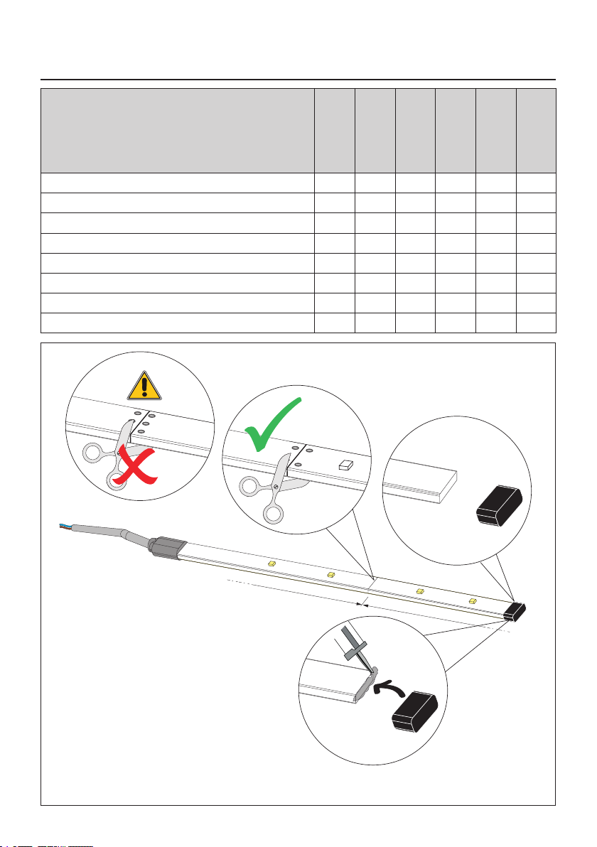
4.1 Regolazione lunghezza 16
4.2 Procedura di installazione BIONIK4 16
4.3 Procedura di installazione BIONIK1-BIONIK4HP-
BIONIK6 16
4.4 Procedura di installazione BIONIK8 17
5 Collaudo 17
6 Manutenzione 17
7 Smaltimento 17
8 Informazioni aggiuntive e contatti 17
9 Dichiarazione di Conformità 17
1 General safety precautions 18
2 Product description 18
3 Technicalspecications18
4 Installation 18
4.1 Adjusting length 18
4.2 Installation procedure BIONIK4 18
4.3 Installation procedure BIONIK1-BIONIK4HP-
BIONIK6 18
4.4 Installation procedure BIONIK8 19
5 Initial testing 19
6 Maintenance 19
7 Disposal 19
8 Additional information and contact details 19
9 Declaration of Conformity 19
1 Allgemeine Sicherheitshinweise 20
2 Beschreibung 20
3 Technische Daten 20
4 Installation 20
4.1 Einstellung der Länge 20
4.2 Installationsverfahren der BIONIK4 20
4.3 Installationsverfahren der BIONIK1-BIONIK4HP-
BIONIK6 20
4.4 Installationsverfahren der BIONIK8 21
5 Abnahmeprüfung 21
6 Wartungsarbeiten 21
7 Entsorgung 21
8 Zusätzliche Informationen und Kontakte 21
9 Konformitätserklärung 21
1 Consignes générales de sécurité 22
2 Description produit 22
3 Caractéristiques techniques 22
4 Installation 22
4.1 Réglage de la longueur 22
4.2 Procédure d'installation BIONIK4 22
4.3 Procédure d'installation BIONIK1
-BIONIK4HP-BION
IK6 22
4.4 Procédure d'installation BIONIK8 23
5 Test 23
6 Entretien 23
7 Élimination 23
8 Informations complémentaires et contacts 23
9 Déclaration de conformité 23
1 Advertencias generales 24
2 Descripción del producto 24
3 Características técnicas 24
4 Instalación 24
4.1 Ajuste de la longitud 24
4.2 Procedimiento de instalación BIONIK4 24
4.3 Procedimiento de instalación BIONIK1-
BIONIK4HP-BIONIK6 24
4.4 Procedimiento de instalación BIONIK8 25
5 Ensayo 25
6 Mantenimiento 25
7 Eliminación 25
8 Información adicional y contactos 25
9 Declaración de Conformidad 25
1 Advertências gerais 26
2 Descrição do produto 26
3 Características Técnicas 26
4 Instalação 26
4.1 Ajuste do comprimento 26
4.2 Procedimento de instalação BIONIK4 26
4.3 Procedimento de instalação BIONIK1-BIONIK4HP-
BIONIK6 26
4.4 Procedimento de instalação BIONIK8 27
5 Teste 27
6 Manutenção 27
7 Descarte 27
8 Informações adicionais e contatos 27
9 Declaração de conformidade 27
ITALIANO
INDICE • INDEX • INDEX • INDEXER • ÍNDICE • ÍNDICE • INDEX • INDEKS
ENGLISH
DEUTSCH
FRANÇAIS
ESPAÑOL
PORTUGUÊS

4
Illustrazioni e schemi • Pictures and schemes • Bilder und Pläne
Illustrations et schémas • Ilustraciones y esquemas • Ilustrações e esquemas
GND
GND
1000 1000
+24V
GND
+24V
+24V
B
A
GND
+24V
B
A
C
CODICE / CODE
BI/004
BI/004/115
BI/004HP
BI/004HP/115
BI/006
BI/006/115
BI/001PE
BI/001PC
BI/001PC/115
BI/008
ALED/4C √
ALED/4C/RGB √
ALED/6C √ √
ALED/6C/RGB √ √
ALED/8C √ √
ALED/8C/RGB √ √
ALED/12C √
ALED/12C/RGB √
Fig. 1

5
BI/004
D
E
F
G
Fig. 2

6
BI/004
I
L
H
M
N
Fig. 3
Fig. 4

7
COM
COMCOM
+24V
+ES
+LAM
COM
COM
LNA
LNB
+SC
10 11 12 13 14 15 16 17 18 19
+LUCI+LUCI
ALED
24 12W max
-
+
blu o nero
blue or black
brown or red
marrone o rosso
BI/004 with ALED
Fig. 5

8
BI/001/PE - BI/004HP - BI/006
Fig. 6
D
E
E
F
G

9
BI/001/PE - BI/004HP - BI/006
Fig. 7
H
I

10
BI/001/PE - BI/004HP - BI/006 with ALED
F1
F2
F3 PROG TEST
+
-
BATTERY (+)
RECEIVER CARD
BATTERY CHARGER
SEC2
ENC2 LED LIGHT
SEC1
BATTERY (-)
123456
Y
X
M
Z
7 8
COM
COM
+24V
+ES
+LAM
COM
COM
LNA
LNB
+SC
10 11 12 13 14 15 16 17 18 19
20
+LUCI
9
ALED
24 12W max
-
+
blu o nero
blue or black
brown or red
marrone o rosso
Fig. 8

11
BI/008
Fig. 9
E
F
DG

12
BI/008
Fig. 10
H

13
BI/008
I
Fig. 11

14
BI/008 with ALED
F1
F2
F3 PROG TEST
+
-
BATTERY (+)
RECEIVER CARD
BATTERY CHARGER
SEC2
ENC2
ENC1 LOCKS
LED LIGHT
SEC1
BATTERY (-)
123456
Y
X
M
Z
7 8
COM
COM
+24V
+ES
+LAM
COM
COM
LNA
LNB
+SC
10 11 12 13 14 15 16 17 18 19
20
+LUCI
ST
COM
COS
FT
COM
ANT
21 22 23 24 25
COM
PED
PP
CH
AP
28 29 30 31 32
ORO
33
COM
3426 27
9
-
+
blu o nero
blue or black
brown or red
marrone o rosso
ALED
24 12W max
Fig. 12

15
ALED/RGB with B73/LTM
COLLEGAMENTO
LUCI ASTA
CONNECTION
BOOM LIGHTS
BIANCO / WHITE
ROSSO / RED
VERDE / GREEN
BLU / BLUE
COLLEGAMENTO
CTRL (LED LIGHT)
CTRL CONNECTION
(LED LIGHT)
Bi-adesivo
Double-sided
adhesive
B73/LTM
COLLEGAMENTO
LUCI ASTA
CONNECTION
BOOM LIGHTS
BIANCO / WHITE
ROSSO / RED
VERDE / GREEN
BLU / BLUE
COLLEGAMENTO
LUCI TESTATA
CONNECTION
HEAD LIGHTS
ROSSO / RED
VERDE / GREEN
BLU / BLUE
BIANCO / WHITE
Fig. 13

16
IT
1 Avvertenze generali
Attenzione: una errata installazione può causare gravi
danni. Leggere attentamente le istruzioni prima di iniziare
l’installazione del prodotto.
Il presente manuale di installazione è rivolto esclusivamente a
personalequalicato.
ROGER TECHNOLOGY declina qualsiasi responsabilità derivante
da un uso improprio o diverso da quello per cui è destinato ed
indicato nel presente manuale.
L’installazione, i collegamenti elettrici e le regolazioni devono
essere effettuati da personale qualicato nell’osservanza della
Buona Tecnica ed in ottemperanza alle normative vigenti. Prima
diiniziarel’installazionevericarel’integritàdelprodotto.
Togliere l’alimentazione elettrica, prima di qualsiasi intervento.
Per l’eventuale riparazione o sostituzione dei prodotti dovranno
essere utilizzati esclusivamente ricambi originali. I materiali
dell’imballaggio (plastica, polistirolo, ecc.) non vanno dispersi
nell’ambiente e non devono essere lasciati alla portata dei
bambini in quanto potenziali fonti di pericolo.
ATTENZIONE! La manipolazione delle parti elettroniche
e dei conduttori deve essere effettuata con la massima
cautela, in quanto trattasi di dispositivi sensibili alle scariche
elettrostatiche.
Maneggiare con estrema cautela la striscia luci a LED, non
torcere, non tirare, non calpestare, non piegare e non forare
l'involucro.
2 Descrizione prodotto
Le luci per l’asta della barriera ROGER BIONIK rendono l’asta più
visibile in tutte le condizioni. Sono composte da una striscia a
LED che va inserita all'interno dell'asta.
Congurando la centrale di comando a cui sono collegate, è
possibilemodicarelamodalitàdiaccensione(parametro79).
Sono fornite in 4 misure:
• ALED/4C: Striscia LED 4 m con cavo.
• ALED/4C/RGB: Striscia LED RGB 4 m con cavo.
• ALED/6C: Striscia LED 6 m con cavo.
• ALED/6C/RGB: Striscia LED RGB 6 m con cavo.
• ALED/8C: Striscia LED 8 m con cavo.
• ALED/8C/RGB: Striscia LED RGB 8 m con cavo.
• ALED/12C: Striscia LED 12 m con cavo.
• ALED/12C/RGB: Striscia LED RGB 12 m con cavo.
3 Caratteristiche tecniche
TENSIONE DI ALIMENTAZIONE 24 V ±10%
POTENZA MASSIMA ASSORBITA
(*) la potenza indicata
corrisponde ai tre colori (R, G,
B) accesi contemporaneamente,
con luce ssa (situazione
comunque non gestita). Nel
caso di luce verde o rossa, la
potenza va divisa per 3.
4W ALED/4C
14W ALED/4C/RGB *
5W ALED/6C
21W ALED/6C/RGB *
7W ALED/8C
28W ALED/8C/RGB *
10W ALED/12C
42W ALED/12C/RGB *
TEMPERATURA DI
FUNZIONAMENTO -20°C +55°C
GRADO DI PROTEZIONE IP54
DIMENSIONI
ALED/4C 15x6x4500 mm - ALED/4C/RGB 15x6x4500 mm
ALED/6C 15x6x7500 mm - ALED/6C/RGB 15x6x7500 mm
ALED/8C 15x6x9500 mm - ALED/8C/RGB 15x6x9500 mm
ALED/12C 15x6x13500 mm - ALED/12C/RGB 15x6x13500 mm
PESO ALED/4C 0,22 kg - ALED/4C/RGB 0,32 kg
ALED/6C 0,29 kg - ALED/6C/RGB 0,39 kg
ALED/8C 0,37 kg - ALED/8C/RGB 0,47 kg
ALED/12C 0,52 kg - ALED/12C/RGB 0,62 kg
4 Installazione
4.1Regolazione lunghezza
Se necessario, accorciare la striscia luci a LED.
1. Scollare e rimuovere il terminale nero part. Ag.1.
2. Tagliare in corrispondenza dei contatti +24V - +24V / GND-
GND (part. B).
ATTENZIONE: NON TAGLIARE in corrispondenza dei contatti
+24V - +24V / A - B / GND - GND.
NOTA: è possibile tagliare la striscia luci a LED ogni 1000 mm.
3. Incollare con del silicone il terminale nero (part. C).
4. Procedere all'installazione come indicato nei capitoli seguenti,
in base al modello di barriera installato.
Ad ogni intervento fare la massima attenzione
nelle operazioni di sblocco/blocco o
movimentazione degli organi meccanici interni.
ATTENZIONE: eseguire le procedure di installazione in
assenza di tensione di rete e con motore fermo.
4.2Procedura di installazione BIONIK4
Se l’asta è montata sul corpo della barriera, smontarla.
Appoggiarel’astasuunasuperciestabileeprestareattenzione
anongrafarla.
PerinserireiLEDprocederecomesegue(gura2):
• SvitarelevitiautolettantiTCC4,2x19dalsupportoasta.
• Togliere il copri-supporto asta (dettaglio D).
• Svitare le viti TCC 4,2x13 e togliere il tappo dall'asta (dettaglio E).
• Introdurre la striscia luci a LED [F]all'internodelproloinPVC
nchénonfuoriescedallatoopposto.
• Piegare l'eccedenza della striscia luci a LED all'interno del
prolo di alluminio e bloccarla con la fascetta in dotazione
(dettaglio G).
• Far passare il cavo della striscia luci a LED all'interno del
percorso [H]comedagura3.
• Bloccareillomedianteifermacavipredisposti[I].
• Far passare il cavo nel foro centrale [L] del supporto asta.
• Far uscire dal lato opposto del motoriduttore il cavo della
striscia luci a led [M], bloccandolo con il ferma cavo in
dotazione [N](g.4).
• Introdurre il cavo all'interno della centrale di comando,
evitando che crei disturbo al movimento dell'automazione.
PER COLLEGAMENTI LUCI ALED: effettuare i collegamenti
alla centrale di comando come indicato in g. 5. Collegare il
lomarrone(orosso)almorsetto+LUCIeilloblu(onero)al
morsetto COM.
Fare riferimento al manuale della centrale di comando per la
congurazionedelleluci(impostazionedelparametro79).
PER COLLEGAMENTI LUCI ALED/RGB: effettuare i collegamenti
con ALED/RGB e consultare le modalità di funzionamento luci
RGBvederegura13emanualediinstallazioneB73/LTM.
4.3 Procedura di installazione BIONIK1-
BIONIK4HP-BIONIK6
Se l’asta è montata sul corpo della barriera, smontarla.
Appoggiarel’astasuunasuperciestabileeprestareattenzione
anongrafarla.
PerinserireiLEDprocederecomesegue(gura6):
• Svitare le 6 viti M8 e togliere la copertura del supporto asta.
• Svitare le viti e togliere il tappo dell’asta (dettaglio D).
• Rimuovereidueprolilateralitrasparenti.
• Assicurandosi che i LED siano rivolti verso l’esterno (dettaglio
E), inserire la striscia a LED nei due proli trasparenti
spingendo delicatamente la parte posteriore.
• Fissare la gomma adesiva sotto la striscia a LED in
corrispondenzadellacurvaperproteggerladalprolotagliente

17
IT
di alluminio (dettaglio F).
• Inserireiprolitrasparentinell’asta.
• Far passare il cavo della striscia luci a LED nel foro centrale del
supporto asta (dettaglio G).
• Far uscire il cavo dal lato opposto del motoriduttore, attraverso
ilguidacavoingommaalcentrodelbilancierepermolla(g.7).
• Introdurre il cavo all’interno del guidacavo in gomma presente
nella struttura portante della barriera.
• Introdurre il cavo all’interno della centrale di comando,
evitando che crei disturbo al movimento dell’automazione.
PER COLLEGAMENTI LUCI ALED: effettuare i collegamenti
alla centrale di comando come indicato in g. 8. Collegare il
lomarrone(orosso)almorsetto+LUCIeilloblu(onero)al
morsetto COM.
Fare riferimento al manuale della centrale di comando per la
congurazionedelleluci(impostazionedelparametro79).
PER COLLEGAMENTI LUCI ALED/RGB: effettuare i collegamenti
con ALED/RGB e consultare le modalità di funzionamento luci
RGBvederegura13emanualediinstallazioneB73/LTM.
4.4Procedura di installazione BIONIK8
Se l’asta è montata sul corpo della barriera, smontarla.
Appoggiarel’astasuunasuperciestabileeprestareattenzione
anongrafarla.
PerinserireiLEDprocederecomesegue(gura9):
• Svitare le 6 viti M8 e togliere la copertura del supporto asta
(dettaglio D).
• Svitare le 2 viti TCC 4,2x13 e togliere il tappo dell’asta
(dettaglio E).
• Introdurre la striscia luci a LED [F]all’internodelproloPVC,
coniLEDversol’alto,nchénonfuoriescedallatoopposto.
• Piegare l’eccedenza della striscia luci a LED all’interno del
prolo in alluminio e bloccarla con la fascetta in dotazione
(dettaglio G).
• Far passare il cavo della striscia luci a LED nel foro centrale del
supporto asta (dettaglio H)g.10.
• Far uscire il cavo dal lato opposto del motoriduttore, attraverso
il guidacavo in gomma al centro del bilanciere per molla
(dettaglio I,g.11).
• Introdurre il cavo all’interno del guidacavo in gomma presente
nella struttura portante della barriera.
• Introdurre il cavo all’interno della centrale di comando,
evitando che crei disturbo al movimento dell’automazione.
PER COLLEGAMENTI LUCI ALED: effettuare i collegamenti
alla centrale di comando come indicato in g. 12. Collegare il
lomarrone(orosso)almorsetto+LUCIeilloblu(onero)al
morsetto COM.
Fare riferimento al manuale della centrale di comando per la
congurazionedelleluci(impostazionedelparametro79).
PER COLLEGAMENTI LUCI ALED/RGB: effettuare i collegamenti
con ALED/RGB e consultare le modalità di funzionamento luci
RGBvederegura13emanualediinstallazioneB73/LTM.
5 Collaudo
Sbloccarelabarrieraevericare,movimentandoamanol'asta,
che il cavo delle luci LED non si tenda erroneamente e non crei
disturbo al movimento dell'automazione.
Vericarel'accensionedituttiiLEDancheconl'automazionein
movimento.
Nel caso di versione RGB, vericare che si accendano i colori
rosso e verde (dipende dalla modalità scelta) e anche il blu (usato
solo nella funzione di stand-by).
6 Manutenzione
Effettuare una manutenzione programmata ogni 6 mesi.
Vericarelostatodipuliziaedilfunzionamento.
Nel caso ci sia presenza di sporco, umidità, insetti o altro, togliere
l’alimentazione di rete e batterie e pulire.
Eseguire nuovamente la procedura di collaudo.
7 Smaltimento
Il prodotto deve essere smaltito sempre da personale
tecnico qualicato utilizzando le procedure idonee.
Questo prodotto è costituito da vari tipi di materiali,
alcuni possono essere riciclati altri devono essere
smaltiti attraverso sistemi di riciclaggio o smaltimento
previsti dai regolamenti locali per questa categoria di prodotto. É
vietatogettarequestoprodottoneiriutidomestici.Eseguirela
“raccolta separata” per lo smaltimento secondo i metodi previsti
dai regolamenti locali; oppure riconsegnare il prodotto al
venditore nel momento dell’acquisto di un nuovo prodotto
equivalente.
Regolamenti locali possono prevedere pesanti sanzioni in caso di
smaltimento abusivo di questo prodotto. Attenzione! Alcune parti
del prodotto possono contenere sostanze inquinanti o pericolose,
se disperse potrebbero provocare effetti dannosi sull’ambiente e
sulla salute umana.
8 Informazioni aggiuntive e
contatti
Tutti i diritti relativi alla presente pubblicazione sono di proprietà
esclusiva di ROGER TECHNOLOGY. ROGER TECHNOLOGY si
riservaildirittodiapportareeventualimodichesenzapreavviso.
Copie,scansioni,ritocchiomodichesonoespressamentevietate
senza un preventivo consenso scritto di ROGER TECHNOLOGY.
SERVIZIO CLIENTI ROGER TECHNOLOGY:
attivo: dal lunedì al venerdì
dalle 8:00 alle 12:00 - dalle 13:30 alle 17:30
Telefono: +39 041 5937023
E-mail: [email protected]
Skype: service_rogertechnology
9 Dichiarazione di Conformità
Il sottoscritto, rappresentante il seguente costruttore:
Roger Technology - Via Botticelli 8, 31021 Bonisiolo di Mogliano
V.to (TV)
DICHIARA che l’apparecchiatura descritta in appresso:
Descrizione: luci per barriera automatica
Modello: ALED
È conforme alle disposizioni legislative che traspongono le se-
guenti direttive:
- 2014/35/UE ;
- 2014/30/UE ;
- 2011/65/UE ;
Echesonostateapplicatetuttelenormee/ospecichetecniche
di seguito indicate:
EN 61000-6-3:2007/A1:2011
EN 61000-6-2:2005
Luogo: Mogliano V.to
Data: 10-05-2014 Firma

EN
18
1 General safety precautions
Warning: incorrect installation may cause severe
damage or injury. Read the instructions carefully before
installing the product.
Thisinstallationmanualisintendedforqualiedpersonnelonly.
ROGER TECHNOLOGY cannot be held responsible for any damage
or injury due to improper use or any use other than the intended
usage indicated in this manual.
Installation, electrical connections and adjustments must be
performed by qualied personnel, in accordance with best
practices and in compliance with applicable regulations. Before
installing the product, make sure it is in perfect condition.
Disconnect the mains electrical power before performing any
work.
Only use original spare parts when repairing or replacing products.
The packaging materials (plastic, polystyrene, etc.) should not be
discarded in the environment or left within reach of children, as
they are a potential source of danger.
WARNING! Handle electronic parts and terminals with extreme
care, as these parts are highly sensitive to static electricity.
Handle the LED light strip with extreme care. Do not twist, pull,
tread on, bend or drill the strip casing.
2 Product description
The lights for the arm of the ROGER BIONIK barrier make the arm
more visible in all conditions.
They are composed of a LED strip that is inserted inside the
boom.
By conguring the command unit they are connected to, it is
possibletocongurethestart-upprocedure(parameter79).
They are supplied in 4 sizes:
• ALED/4C: Strip LED 4 metres with connections cable.
• ALED/4C/RGB: Strip LED RGB 4 metres with connections cable.
• ALED/6C: Strip LED 6 metres with connections cable.
• ALED/6C/RGB: Strip LED RGB 6 metres with connections cable.
• ALED/8C: Strip LED 8 metres with connections cable.
• ALED/8C/RGB: Strip LED RGB 8 metres with connections cable.
• ALED/12C: Strip LED 12 metres with connections cable.
• ALED/12C/RGB: Strip LED RGB 12 metres with connections cable.
3 Technical specications
MAINS POWER VOLTAGE 24 V ±10%
MAXIMUM MAINS POWER
ABSORPTION
(*) the indicated power
corresponds to the three colours
(R, G, B) switched on at the same
time, with steady light (situation
not managed in any case). In the
case of green or red light, the
power is to be divided by 3.
4W ALED/4C
14W ALED/4C/RGB *
5W ALED/6C
21W ALED/6C/RGB *
7W ALED/8C
28W ALED/8C/RGB *
10W ALED/12C
42W ALED/12C/RGB *
OPERATING TEMPERATURE -20°C +55°C
DEGREE OF PROTECTION IP54
PRODUCT DIMENSIONS
ALED/4C 15x6x4500 mm - ALED/4C/RGB 15x6x4500 mm
ALED/6C 15x6x7500 mm - ALED/6C/RGB 15x6x7500 mm
ALED/8C 15x6x9500 mm - ALED/8C/RGB 15x6x9500 mm
ALED/12C 15x6x13500 mm - ALED/12C/RGB 15x6x13500 mm
WEIGHT ALED/4C 0,22 kg - ALED/4C/RGB 0,32 kg
ALED/6C 0,29 kg - ALED/6C/RGB 0,39 kg
ALED/8C 0,37 kg - ALED/8C/RGB 0,47 kg
ALED/12C 0,52 kg - ALED/12C/RGB 0,62 kg
4 Installation
4.1Adjusting length
If necessary, the LED light strip must be shortened.
1. Detach and remove the terminal black cap (Ag.1).
2. Cut at the contacts + 24V - + 24V / GND-GND (detail B).
ATTENTION: DO NOT CUT at the contacts + 24V - + 24V /
A - B / GND - GND.
NB: It is possible to cut the LED light strip every 1000 mm.
3. Fix the terminal black cap (C) onto the strip with silicone
sealant.
Proceed with the installation as indicated in the following
chapters, based on the installed barrier model.
Whenever corrective actions are carried out, pay
the utmost attention when releasing, locking or
moving the internal mechanical parts. These operations
could be hazardous for the user.
WARNING: only perform the installation procedures
with the unit disconnected from mains and with the
motor at a standstill.
4.2Installation procedure BIONIK4
If the arm is mounted on the barrier’s body, remove it.
Place the arm on a stable surface, making sure it is not scratched.
To insert the LEDs, proceed as follows (Fig. 2):
• Undo the 4.2x19 mm self-tapping cylindrical socket head cap
screws from the boom mount.
• Remove the boom mount cover (detail D).
• Undo the 4.2x13 mm cylindrical socket head cap screws and
remove the boom end cap (detail E).
• Feed the LED light strip [F]into the PVC moulding until it
comes out at the other end.
• Fold the excess length of LED light strip, push it into the
aluminium moulding and fasten with the cable tie included
(detail G).
• Route the cable of the LED light strip correctly [H]as shown
ingure3.
• Secure the cable with the relative cable fasteners [I].
• Feed the cable in the hole in the centre of the boom mount [L].
• Push the LED light strip cable out of the opposite end of the
gear motor unit [M], securing with the cable fastener included
[N](g.4).
• Feed the cable into the control unit, ensuring that the cable will
not interfere with the movements of the automation system.
FOR ALED LIGHT CONNECTIONS: connect the cable to the control
unitasshowning.5.Connectthebrown(or red)wiretothe
+LUCI terminal and connect the blue (or black) wire to the COM
terminal.
Refer to parameter 79 of the control unit for setting up the LED
light strip.
FOR ALED/RGB LIGHT CONNECTIONS: make connections with
ALED/RGBandrefertoRGBlightoperationmodesseegure13
and installation manual B73/LTM.
4.3Installation procedure BIONIK1-
BIONIK4HP-BIONIK6
If the arm is mounted on the barrier’s body, remove it.
Place the arm on a stable surface, making sure it is not scratched.
ToinserttheLEDsproceedasfollows(gure5):
• Unscrew the 6 M8 screws and remove the boom support
cover.
• Unscrew the screws and remove the cap of the boom (detail D).
• Removethetwotransparentsideproles.
• Ensuring that the LEDs are facing outwards (detail E), insert
the LED strip into the two transparent proles by gently

EN
19
pushing the rear part.
• Fix the adhesive rubber under the LED strip at the curve to
protectitfromthesharpaluminiumprole(detail F).
• Insertthetransparentprolesintheboom.
• Pass the LED light strip cable through the centre hole of the
boom support (detail G).
• Push the cable out of the opposite end of the gear motor unit
through the rubber cable guide to the centre of the spring
linkage lever (Fig. 7).
• Introduce the cable into the rubber cable guide present in the
barrier support structure.
• Introduce the cable into the control unit, ensuring that the
cable will not interfere with the movements of the automation
system.
FOR ALED LIGHT CONNECTIONS: connect the cable to the control
unitasshowning.8.Connectthebrown(or red)wiretothe
+LUCI terminal and connect the blue (or black) wire to the COM
terminal.
Refer to parameter 79 of the control unit for setting up the LED
light strip.
FOR ALED/RGB LIGHT CONNECTIONS: make connections with
ALED/RGBandrefertoRGBlightoperationmodesseegure13
and installation manual B73/LTM.
4.4Installation procedure BIONIK8
If the arm is mounted on the barrier’s body, remove it.
Place the arm on a stable surface, making sure it is not scratched.
To insert the LEDs, proceed as follows (Fig. 9):
• Unscrew the 6 M8 screws and remove the boom support cover
(detail D).
• Unscrew the 2 TCC 4,2x13 screws and remove the cap of the
boom (detail E).
• Insert the LED light strip [F] insidethe PVCprole, withthe
LEDs upwards, until it comes out from the opposite end.
• Fold the excess length of LED light strip into the aluminium
moulding and fasten it with the cable tie included (detail G).
• Pass the LED light strip cable through the centre hole of the
boom support (detail H) Fig. 10.
• Push the cable out of the opposite end of the gear motor unit
through the rubber cable guide to the centre of the spring
linkage lever (detail I,g.11).
• Introduce the cable into the rubber cable guide present in the
barrier support structure.
• Introduce the cable into the control unit, ensuring that the
cable will not interfere with the movements of the automation
system.
FOR ALED LIGHT CONNECTIONS: connect the cable to the control
unitasshowning.12.Connectthebrown(orred)wiretothe
+LUCI terminal and connect the blue (or black) wire to the COM
terminal.
Refer to parameter 79 of the control unit for setting up the LED
light strip.
FOR ALED/RGB LIGHT CONNECTIONS: make connections with
ALED/RGBandrefertoRGBlightoperationmodesseegure13
and installation manual B73/LTM.
5 Initial testing
Unlock the barrier, lift and lower the boom by hand and check that
the LED light strip cable is not tautened excessively and does not
interfere with the movements of the automation system.
ConrmthelightingofallLEDswithautomationinmotion.
In the case of the RGB version, check that the colours red and
green (depending on the chosen mode) and also blue (only used
in the stand-by function) light up.
6 Maintenance
Perform scheduled maintenance every 6 months.
Check cleanliness and correct functioning.
If any dirt, moisture, insects or other foreign matter is found in
the unit, disconnect from mains power and from the batteries and
clean.
Repeat the initial installation test procedure after cleaning.
7 Disposal
This product may only be uninstalled by qualied
technical personnel, following suitable procedures for
removing the product correctly and safely. This product
consists of numerous different materials. Some of these
materials may be recycled, while others must be
disposed of correctly at the specic recycling or waste
management facilities indicated by local legislation applicable for
this category of product.
Do not dispose of this product as domestic refuse. Observe local
legislation for differentiated refuse collection, or hand the product
over to the vendor when purchasing an equivalent new product.
Local legislation may stipulate severe nes for the incorrect
disposal of this product. Warning! some parts of this product
may contain substances that are harmful to the environment or
dangerous and that may damage the environment or pose a risk
to health if disposed of incorrectly.
8 Additional information and
contact details
ROGER TECHNOLOGY is the exclusive owner of all rights
regarding this publication.
ROGER TECHNOLOGY reserves the right to implement any
modicationswithoutpriornotication.Copyingorscanningof
or any alterations to this document are prohibited without the
express prior permission of ROGER TECHNOLOGY.
ROGER TECHNOLOGY CUSTOMER SERVICE:
business hours: Monday to Friday
8-12 am and 1.30-5.30 pm
Telephone no: +39 041 5937023
E-mail: [email protected]
Skype: service_rogertechnology
9 Declaration of Conformity
I the undersigned, as acting legal representative of the manufacturer:
Roger Technology - Via Botticelli 8 - 31021 Bonisiolo di Mogliano
V.to (TV)
hereby DECLARE that the appliance described hereafter:
Description: automatic barrier lights
Model: ALED
Is conformant with the legal requisites of the following directives:
- 2014/35/UE ;
- 2014/30/UE ;
- 2011/65/UE ;
and that all the standards and/or technical requirements indi-
cated as follows have been applied:
EN 61000-6-3:2007/A1:2011
EN 61000-6-2:2005
Place: Mogliano V.to
Date: 10-5-2014 Signature

DE
20
1 Allgemeine Sicherheitshinweise
Achtung: Eine falsche Montage kann schwere Schäden
zur Folge haben. Lesen Sie die Anleitungen vor der
Montage des Produktes aufmerksam durch.
Das vorliegende Installationshandbuch ist ausschließlich für
Fachpersonal bestimmt.
ROGER TECHNOLOGY lehnt jede Haftung für Schäden, die durch
unsachgemäßen oder nicht bestimmungsgemäßen, den Angaben dieses
Handbuchs nicht entsprechenden Gebrauch verursacht werden, ab.
Die Montage, die elektrischen Anschlüsse und Einstellungen sind
fachgerecht und unter Beachtung der geltenden Vorschriften durch
qualiziertesPersonalauszuführen. Vor Beginn der Montage ist
der einwandfreie Zustand des Produkts zu überprüfen.
Vor jeglichem Eingriff die Stromversorgung trennen.
Bei Reparaturen oder Austausch der Produkte dürfen
ausschließlich Originalersatzteile verwendet werden. Die
Verpackungsmaterialien (Kunststoff, Polystyrol usw.) müssen
sachgemäß entsorgt werden und dürfen nicht in Kinderhände
gelangen, da sie eine Gefahrenquelle darstellen können.
ACHTUNG! Beim Umgang mit elektronischen Bauteilen und Leitern
ist mit besonderer Sorgfalt vorzugehen, da die Vorrichtungen
empndlich auf elektrostatische Entladungen reagieren.
Den LED Lichtstreifen vorsichtig behandeln, nicht verdrehen,
nicht ziehen, nicht darauf treten, nicht knicken und die Hülle
nicht durchbohren.
2 Beschreibung
Die Beleuchtungen für den Baum der Schranke ROGER BIONIK
sorgen dafür, dass der Baum bei allen Lichtverhältnissen besser
zu sehen ist. Sie bestehen aus einem LED-Beleuchtungsband, das
an des Baumes eingebaut wird.
Die Art und Weise für das Einschalten kann, indem die Steuerzentrale
entsprechendkonguriertwird,geändertwerden(Par.79).
Lieferbar sind sie in 4 Maßen:
• ALED/4C: LED-Lichter 4 m
• ALED/4C/RGB: RGB-LED-Lichter 4 m
• ALED/6C: LED-Lichter 6 m
• ALED/6C/RGB: RGB-LED-Lichter 6 m
• ALED/8C: LED-Lichter 8 m
• ALED/8C/RGB: RGB-LED-Lichter 8 m
• ALED/12C: LED-Lichter 12 m
• ALED/12C/RGB: RGB-LED-Lichter 12 m
3 Technische Daten
VERSORGUNGSSPANNUNG 24 V ±10%
MAXIMAL VOM STROMNETZ
AUFGENOMMENE LEISTUNG
(*) die angegebene Leistung
entspricht den drei gleichzeitig
eingeschalteten Farben (R, G,
B) mit Dauerlicht (Situation in
jedem Fall nicht beherrscht). Bei
grünem oder rotem Licht ist die
Leistung durch 3 zu teilen.
4W ALED/4C
14W ALED/4C/RGB *
5W ALED/6C
21W ALED/6C/RGB *
7W ALED/8C
28W ALED/8C/RGB *
10W ALED/12C
42W ALED/12C/RGB *
BETRIEBSTEMPERATUR
-20°C +55°C
SCHUTZGRAD IP54
PRODUKTMASSE
ALED/4C 15x6x4500 mm - ALED/4C/RGB 15x6x4500 mm
ALED/6C 15x6x7500 mm - ALED/6C/RGB 15x6x7500 mm
ALED/8C 15x6x9500 mm - ALED/8C/RGB 15x6x9500 mm
ALED/12C 15x6x13500 mm - ALED/12C/RGB 15x6x13500 mm
GEWICHT ALED/4C 0,22 kg - ALED/4C/RGB 0,32 kg
ALED/6C 0,29 kg - ALED/6C/RGB 0,39 kg
ALED/8C 0,37 kg - ALED/8C/RGB 0,47 kg
ALED/12C 0,52 kg - ALED/12C/RGB 0,62 kg
4 Installation
4.1Einstellung der Länge
Wenn nötig, muss der LED-Lichtstreifen verkürzt werden.
1. Das schwarze Endstück Detail AAbb. 1 ablösen und entfernen.
2. Schnitt an den Kontakten + 24V - + 24V / GND-GND (Detail C).
ACHTUNG: NICHT SCHNEIDEN an den Kontakten + 24V - +
24V / A - B / GND - GND.
HINWEIS: Der LED-Lichtstreifen kann alle 1000 mm
durchgeschnitten werden.
3. Das schwarze Endstück mit Silikon verkleben (Detail C).
4. Mit der Installation fortfahren, come indicato nei capitoli
seguenti, in base al modello di barriera installato.
Bei jedem Eingriff, bei dem Verriegelungs-/
Entriegelungsarbeiten durchgeführt oder
innere mechanische Maschinenteile in Bewegung
versetzt werden, strikte Vorsicht walten lassen.
ACHTUNG: Die Installationsverfahren bei unterbrochener
Netzspannung und stehendem Motor durchführen.
4.2Installationsverfahren der BIONIK4
Montieren Sie den Baum ab, falls er am Block der Schranke
montiert ist.
Legen Sie den Baum auf einer stabilen Fläche ab und achten Sie
darauf, dass er nicht verkratzt wird.
Gehen Sie beim Einbau der LED-LEUCHTEN folgendermaßen vor
(Abbildung 2):
• Die Blechschrauben TCC 4,2x19 von dem Schlagbaumträger
lösen.
• Die Schlagbaumträger-Abdeckung entfernen (Detail D).
• Die Schrauben TCC 4,2x13 abschrauben und den Deckel von
dem Schlagbaum entfernen (Detail E).
• Den LED-Lichtstreifen [F] im Inneren des Prols aus PVC
einsetzen, bis er von der gegenüberliegenden Seite vorsteht.
• Den Überschuss des LED-Lichtstreifens im Inneren des
Aluminiumprolsknickenund mit dermitgelieferten Schelle
blockieren (Detail G).
• Das Kabel des LED-Lichtstreifens in das Innere des
Kabelverlaufs führen [H], wie in Abbildung 3 dargestellt.
• Den Draht mit der vorgesehenen Kabelsicherung blockieren [I].
• Das Kabel in das mittlere Loch [L] des Schlagbaumträgers
führen.
• Von der gegenüberliegenden Seite des Getriebemotors das
Kabel des LED-Lichtstreifens austreten lassen [M] und mit der
mitgelieferten Kabelsicherung blockieren [N] (Abb. 4).
• Das Kabel in das Steuergerät einfügen, dabei darauf achten,
dass es die Bewegung des Antriebs nicht stört.
FÜR ALED-LICHTANSCHLÜSSE: Die Anschlüsse an das Steuergerät
durchführen, wie in Abbildung 5 dargestellt. Den braunen (oder
roten) Draht an die Klemme +LUCI und den blauen Zwecks der
Konguration der Beleuchtungen (Einstellen der Parameter 79)
ziehen Sie bitte das Handbuch der Steuerzentrale zurate.
FÜR ALED/RGB-LICHTANSCHLÜSSE: Stellen Sie die Anschlüsse
mit ALED/RGB her und beachten Sie die RGB-Lichtbetriebsarten,
siehe Abbildung 13 und Installationshandbuch B73/LTM.
4.3Installationsverfahren der BIONIK1-
BIONIK4HP-BIONIK6
Montieren Sie den Baum ab, falls er am Block der Schranke
montiert ist.
Legen Sie den Baum auf einer stabilen Fläche ab und achten Sie
darauf, dass er nicht verkratzt wird.
Zum Einsetzen der LED wie folgt vorgehen (Abbildung 6):
• Die 6 Schrauben M8 abschrauben und die Abdeckung der
Schlagbaumhalterung entfernen.
This manual suits for next models
9
Table of contents
Languages:
Other Roger Automatic Barrier manuals
Popular Automatic Barrier manuals by other brands

Nice
Nice M7BAR Instructions for installation and use

Telcoma
Telcoma RAP-3 INSTRUCTION HANDBOOK AND SPARE PARTS CATALOGUE

CAME
CAME 803XA-0200 quick start guide

SOMFY
SOMFY Home Motion LEVIXO 30 RTS installation instructions

fadini
fadini CORAL 1050 instruction manual

DoorKing
DoorKing 1620 Series installation manual