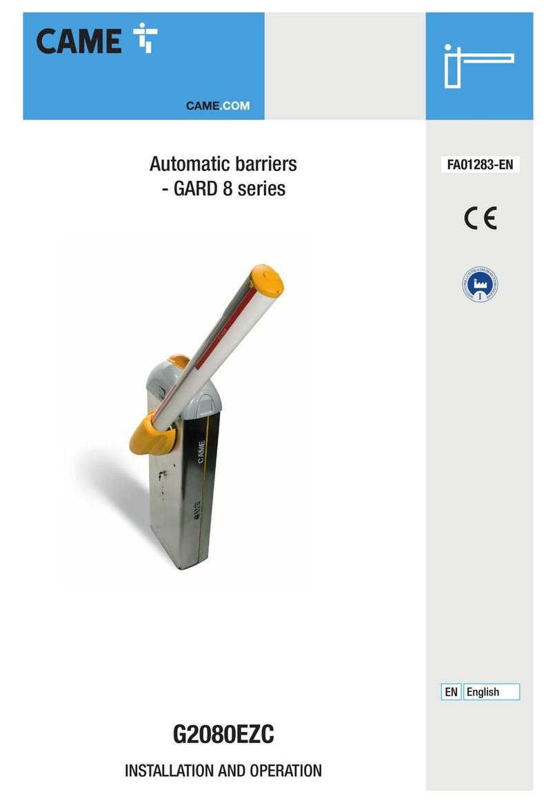
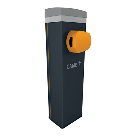
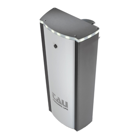
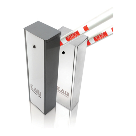
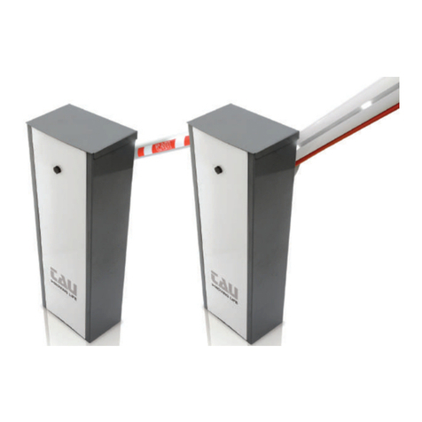
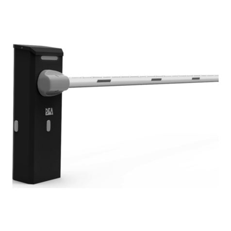
tau LUXE-S User manual

IT - Istruzioni originali
MANUALE D’USO E MANUTENZIONE
USE AND MAINTENANCE MANUAL
BEDIENUNGS - UND WARTUNGSANLEITUNG
MANUEL D’EMPLOI ET D’ENTRETIEN
MANUAL DE USO Y MANTENIMIENTO
LUXE-S
D-MNL0LUXE-S 22-11-2022 - Rev.02

2
LINGUA | LANGUAGE | SPRACHE | LANGUE | IDIOMA | LÍNGUA
INDICE / INDEX IT EN DE FR ES PT
1. CONDIZIONI DI UTILIZZO / CONDITIONS OF USE / NUTZUNGSBEDINGUNGEN / ONDITIONS
D’UTILISATION / CONDICIONES DE USO / CONDIÇÕES DE UTILIZAÇÃO 3 14 25 37 49 61
2. DESCRIZIONE E CARATTERISTICHE / DESCRIPTION AND CHARACTERISTICS
/ BASCHREIBUNG UND MERKMALE / DESCRIPTION ET CARACTÉRISTIQUES /
DESCRIPCIÓN Y CARACTERÍSTICAS / DESCRIÇÃO E CARACTERÍSTICAS
4 15 26 38 50 62
3. ACCESSORI OPZIONALI / OPTIONAL ACCESSORIES / SONDERZUBEHÖR / ACCESSOIRES EN
OPTION / ACCESORIOS OPCIONALES / ACESSÓRIOS OPCIONAIS 4 15 26 38 50 62
4. MISURE DI INGOMBRO / OVERALL DIMENSIONS / NUTZUNGSBEDINGUNGEN / MESURES
D’ENCOMBREMENT / DIMENSIONES EXTERIORES / DIMENSÕES TOTAIS 5 16 27 39 51 63
5. IMPIANTO TIPO / TYPICAL SYSTEM / TYPISCHE ANLAGE / INSTALLATION TYPE / INSTA-
LACIÓN TIPO / SISTEMA TÍPICO 6 16 28 40 52 64
6. INSTALLAZIONE / INSTALLATION / INSTALLATION / INSTALLATION / INSTALACIÓN /
INSTALAÇÃO 6 17 28 40 52 64
6.1 Veriche preliminari / Preliminary checks / Vorbereitende Überprüfungen /
Vérications préliminaires / Controles preliminares / Vericações preliminares 6 17 28 40 52 64
6.2 Preparazione base automazione / Automation base preparation / Vorbereitung
der Basis der Automatisierung / Préparation base automatisme / Preparación bási-
ca del automatismo / reparação da base da automatização
7 17 29 41 53 65
6.3 Installazione del gruppo barriera / Installation of the barrier group / Installation
der Baugruppe Schranke / Installation du groupe barrière / Installazione del gruppo
barriera / Instalar a barreira
7 18 29 41 53 65
6.4 Regolazione senso della barriera / Barrier direction adjustment / Einstellung der
bewegungsrichtung der schranke / Réglage du sens de la barrière / Regulación del
sentido de la barrera / Ajuste da direção de barreira
7 18 30 42 54 66
6.5 Sblocco manuale / Manual release / Manuelle Entriegelung / Déverrouillage
manuel / Desbloqueo manual / Abertura manual
8 18 30 42 54 66
6.6 Fissaggio asta / Bar xing / Befestigung der Stange / Fixation barre / Fijación del
asta / Fixação da haste
8 19 30 42 54 66
6.7 Montaggio molla / Spring tting / Montage der Feder / Montage ressort / Mon-
taje de muelle / Colocação da mola
9 20 31 43 55 67
6.8 Bilanciamento dell’asta / Bar balancing / Ausgleichen des Gewichts der Stange / équi-
librage barre / Compensación del asta / Balanceamento da haste
9 20 32 44 56 68
6.9 Collegamenti elettrici / Electrical connections / Elektrische Anschlüsse
Branchements électriques / Conexiones eléctricas / Ligações eléctricas 10 21 32 44 56 68
6.10 Regolazione necorsa elettrici (LUXE-SE) / Electric limit switches - adjustment
(LUXE-SE) / Einstellung der elektrischen endanschläge (LUXE-SE) / Reglage n de
course electriques (LUXE-SE) / Ajuste de los nales de carrera eléctricos (LUXE-SE) /
Ajuste dos ns de curso elétricos (LUXE-SE)
10 21 33 45 57 69
6.11 Regolazione arresti meccanici / Mechanical stops adjustment / Einstellung der
mechanischen endanschläge / Réglage n de course mécaniques / Regulación n
de carrera mecánicos / Ajuste dos batentes mecânicos
10 21 33 45 57 69
6.12 Ultime operazioni / Last operations / Letzte Arbeiten / Dernières opérations /
Últimas operaciones / Últimas operações 11 22 33 45 57 69
7. USO / USE / BEDIENUNG / UTILISATION / USO / UTILIZAÇÃO 11 22 33 45 57 69
8. MANUTENZIONE / MAINTENANCE / WARTUNG / MAINTENANCE / MANTENIMIENTO /
MANUTENÇÃO 11 22 34 46 58 70
9. MANUTENZIONE STRAORDINARIA E RIPARAZIONI / EXTRAORDINARY MAINTENANCE
AND REPAIRS / AUßERGEWÖHNLICHE WARTUNG UND REPARATUREN / MAINTENANCE
EXTRAORDINAIRE ET RÉPARATIONS / MANTENIMIENTO EXTRAORDINARIO Y REPARACIONES
/ REPARAÇÕES E MANUTENÇÃO EXTRAORDINÁRIA
12 23 34 46 58 70
10. DIAGNOSI DELLE CAUSE DI GUASTO PIÙ COMUNE / TROUBLESHOOTING
DIAGNOSE DER HÄUFIGSTEN STÖRUNGSURSACHEN / DIAGNOSTIC DES CAUSES DE
PANNES LES PLUS COURANTES / DIAGNÓSTICO DE LAS CAUSAS DE AVERÍA MÁS CO-
MUNES / AVARIAS
12 23 35 47 58 70
11. DISMISSIONE / DECOMMISSION / ABBRUCH / DÉMANTÈLEMENT / DESGUACE /
DESACTIVAÇÃO - DESMANTELAMENTO 12 23 35 47 59 71
12. TRASPORTO / TRANSPORT / TRANSPORT / TRANSPORT / TRANSPORTE / TRANSPORTE 12 23 35 47 59 71
GARANZIA: CONDIZIONI GENERALI / GUARANTEE: GENERAL CONDITIONS / GARANTIE:
ALLGEMEINE BEDINGUGEN / GARANTIE: CONDITIONS GÉNÉRALES / GARANTÍA: CONDI-
CIONES GENERALES / GARANTIA: CONDIÇÕES GERAIS
13 24 35 47 59 71

14
The data described in this handbook are purely a guide. TAU reserves the right to change them in any moment.
The manufacturer reserves the right to modify or improve products without prior notice. Any inaccuracies or errors found in this
handbook will be corrected in the next edition.
When opening the packing please check that the product is intact. Please recycle materials in compliance with current regulations.
This product may only be installed by a qualied tter. The manufacturer declines all liability for damage to property and/or
personal injury deriving from the incorrect installation of the system or its non-compliance with current law (see Machinery
Directive).
INSTALLATION WARNINGS. GENERAL SAFETY REQUIREMENTS
1) Carefully read all instructions before installation, as they provide important instructions regarding the safety, installa-
tion, operation and maintenance. Incorrect installation or use of the product may lead to serious physical injury.
2) Never leave packaging materials (plastic, polystyrene etc.) within the reach of children as they constitute a potential hazard.
3) Keep the instructions in a safe place for future consultation.
4) This product has been designed and constructed exclusively for the use specied in this documentation. Any other use not specied
herein may impair product integrity and/or constitute a hazard.
5) TAU Srl declines all liability for improper use or use other than as specied for this automation.
6) Do not install the unit in an explosive environment: the presence of either gas or ammable fumes is a serious safety risk.
7) The mechanical elements must comply with the requirements as stated in the standards EN 12604 and EN 12605. For non European
member states, in addition to the national reference standards, the above-mentioned standards must be observed to ensure an
adequate level of safety.
8) TAU Srl is not responsible for failure to observe Good Practice in construction of the gates/doors to be power-operated, nor any
deformations occurring during use.
9) Installation must be performed in compliance with the standards EN 12453 and EN 12445. For non European member states, in ad-
dition to the national reference standards, the above-mentioned standards must be observed to ensure an adequate level of safety.
10) Before performing any operations on the system, disconnect from the mains and detach the batteries.
11) On the automation power line, install a device for disconnection from the power mains with a gap between contacts equal to or
greater than 3 mm. Use of a 6A thermal magnetic circuit breaker with multi-pole switch is recommended.
12) Check upline of the system that there is a residual current circuit breaker with a threshold of 0.03 A.
13) Ensure that the earthing system is to professional standards and connected to the metal section of the gate/door.
14) The automation is equipped with an intrinsic anti-crushing safety device comprising a torque control. The trip threshold must in all
cases be checked as stated in the standards specied in point 9.
15) The safety devices (standard EN 12978) enable the protection of danger areas from risks associated with mechanical move-
ments such as crushing, dragging and shearing.
16) The use of at least one luminous indicator is recommended for each system (900T-LED, 800LA, 800LL), as well as a warning notice
xed suitably to the frame structure, in addition to the devices specied in point 15.
17) TAU declines all liability for the safety and ecient operation of the automation in the event of using system components not pro-
duced by TAU.
18) For maintenance, use exclusively original TAU parts.
19) Never modify components that are part of the automation system.
20) The installer must provide all information regarding manual operation of the system in the event of an emergency and supply the
system User with the “User Guide” enclosed with the product.
21) Never allow children or other persons to stay in the vicinity of the product during operation.
22) Keep all radio controls or other pulse supplier device out of the reach of children to prevent inadvertent activation of the automa-
tion.
23) Transit should only occur with the automation stationary.
24) The user must never attempt to repair or intervene directly on the product; always contact qualied personnel for assistance.
25) It is strictly forbidden to use high pressure water cleaners or jets of water in general to clean the automation.
26) Maintenance: at least every six months, make a general check of the system, with special reference to the eciency of the safety
devices (including, when envisaged, the operator thrust force) and release mechanisms.
27) All actions not expressly envisaged in these instructions are strictly prohibited.
1. CONDITIONS OF USE
The LUXE-S automatic barrier has been designed for use in private or public car parks, residential areas or areas of intense trac.
ENGLISH
15
2. DESCRIPTION AND CHARACTERISTICS
The rapid type LUXE-S series barriers are suitable for controlling entrances and car parks where a short waiting time and in-
tensive use are required. IT IS STRICTLY FORBIDDEN TO USE THE EQUIPMENT FOR PURPOSES OR SITUATIONS THAT ARE
DIFFERENT FROM THOSE STIPULATED.
LUXE-S / SI LUXE-SR LUXE-SE
Frequency 50 - 60 Hz
Power 230 V AC ±10%
Absorbed power 250 W 180 W
Motor 18V DC 24V DC 230V AC
Motor absorbed current (max.) 1 A 1,2 A
Max. torque 155 Nm 160 Nm 160 Nm
Reduction ratio 1/191
Min. opening time 2,2 s. 1,8 s. 2,2 s.
Protection level IP 54
Work cycle 100 % 120/hour
Operating temperature -20°C ÷ +55°C
Max. round boom lenght 4 m 3 m 3 m
Max. elliptical boom lenght 4 m - -
Weight 47 Kg 46 Kg 46 Kg
When the system is in the 12V DC mode and is powered by the battery only (in the event of a power failure or when used in con-
junction with a photovoltaic panel), the gear motor’s output (power and speed) is reduced by approximately 30%.
3. OPTIONAL ACCESSORIES
1. K-800CPLUXESM : Foundation counterplate
2. P-800AT: Adjustable fork support for bar
3. P-900OPTIC: Photoelectric cells
4. P-200BATT: Battery 12V
5. P-800LABTSE: Joint for elliptical boom (LUXE-S and LUXE-M)
* It is not reccomended the installation for intensive use.
SPRING A) M-060MGREENL (ø 4,2 mm) Color: Light green RAL 6019 B) M-060MGREEN (ø 5,2 mm) Color: Green RAL 6002
C) M-060MBLU (ø 6,2 mm) Color: Blue RAL 5003 D) M-060MRED (ø 7 mm) Color: Red RAL 3000
BAR AND ACCESSORIES LUXE-S + 800ABT/AFI
LUXE-SR / LUXE-SE (Round boom)
BAR LENGHT
2 m 2,5 m 3 m 3,5 m 4 m
800AFI4 (RBLO) / 800ABT1 (RBLO-E) A A
800AFI4 (RBLO) / 800ABT1 (RBLO-E) + 800AT A A B C D
800AFI4+800FPT2 C C
The LUXE-S barrier is supplied as standard with the “D” spring (M-060MRED), suitable for booms up to 4 m.
The LUXE-SE barrier is supplied as standard with the “B” spring (M-060MGREEN), suitable for booms up to 3 m.
For dierent boom lengths or when further optionals are to be installed please order a dierent spring as per enclosed chart.
SPRING
A) M-060MGREENL (ø 4,2 mm)
Color: Light green RAL 6019 B) M-060MGREEN (ø 5,2 mm)
Color: Green RAL 6002 E) M-060MYELLOW (ø 9 mm)
Color: Yellow RAL 1004
C) M-060MBLU (ø 6,2 mm)
Color: Blue RAL 5003 D) M-060MRED (ø 7 mm)
Color: Red RAL 3000
BAR AND ACCESSORIES LUXE-S + 800AE
(Elliptical boom)
BAR LENGHT
2 m 2,5 m 3 m 3,5 m 4 m
800AE A B
800AE + 800AT A B C D D*
800AE + 800AT + 800LABTSE - - E E E
800AE+800FPL D* D*
* Eyelet in the max. load position
For boom lengths equal or greater than 3 mt. it must use (mandatory) the ground boom support or the pendulum support.
ENGLISH

16
ATTENTION: PASSAGE WIDTH EQUALS BAR LENGTH LESS 260 mm (see pic. #1).
For dierent boom lengths or when further optionals are to be installed please order a dierent spring as per enclosed chart.
4. OVERALL DIMENSIONS
The main dimensions of the barrier are indicated in pic. 1; pic.2 illustrates the dimensions of the foundation base plate.
950
346
239
233.7
379
1097.5
471
109.6
471
1097.5
379
935
233.7
124.4
360.8
239
MAX 4000
Max 4000
111.4
Ø70
289.5
289.5
Asta elittica
Asta tonda
Fig.1
12,5
100
379
3
233,7
K-800CPLUXESM
Fig.2
5. TYPICAL SYSTEM
1 Barrier cabinet 6 Photocells
2 Control panel 7 Bar rest (xed)
3 Round section aluminium boom
Elliptical section aluminium boom 8 Metal mass sensor
4 LED strip 9 Bar gasket
5 Photocell pillar
ENGLISH

17
1
3
2
3
4
7
8
9
4
5
6
6. INSTALLATION
Installation must be carried out by skilled and qualied personnel in compliance with the regulations in force.
6.1 Preliminary checks
The following principles must be followed in addition to the functionality:
1_ before installing the bar, make sure that the area above the bar is free of all obstacles (balconies, cables, trees, etc.)
2_ a good visibility at a sucient distance to avoid collision (pay attention to bushes, etc.)
3_ suitable base to guarantee the secure positioning of the barrier
4_ absence of pipes and/or electrical cables that could be damaged when preparing the site
5_ minimization of the length of the electrical cables that are necessary to operates the barrier
6_ positioning in accordance with the present national standards.
6.2 Automation base preparation
A
B
Fig.4
Create a rectangular, suitably sized oor slab (A pic.4) with the ho-
les for the exiting cables. Use the foundation counterplate (B pic. 4),
with the 4 anchors supplied to be buried in concrete; or, once the
oor slab is completed, x the cabinet to the barrier with 4 M10x120
foundation plugs (C pic. 4). The slab thickness must be at least 10cm
and can be increased as required.
ENGLISH

18
6.3 Installation of the barrier group
Fig.5
The barrier is now placed in position, without the bar, and xed to
the base by securely tightening the nuts to the tie bars (or anchor
bolts). The perfect stability of the anchorage is controlled and if ne-
cessary, the nuts are tightened further.
6.4 Barrier direction adjustment
Right-hand barriers (RH) are barriers that have the cabinet on the right-hand side viewed from the inside of the passageway (the door is
normally on the inside).
The barrier can be right-hand operating (RH) by tting the plates as shown in A Fig. 4.
Left-hand barriers (LH) are barriers that have the cabinet on the left-hand side viewed from the inside of the passageway (the door is
normally on the inside).
The barrier can be left-hand operating (LH) by tting the plates as shown in D Fig. 4.
“LUXE-S” is normally delivered in the RIGHT-HAND (RH) version. If it needs to be transformed to LEFT-HAND (LH), proceed as follows:
1_ after removing the nuts and washers, remove the upper limit switch support, rotate it 180° and fasten it again.
2_ reverse the lever and the spring
3_ Once the direction of the barrier has been changed, the motor connections must be reversed (see instructions K206MA) For LUXE-S,
instructions K101M for LUXE-SE).
Note: once the direction of the barrier has been changed, the position of the devices are inverted.
D1
D1
C1
C2
C2
C1
13
13
D2
D2
6.5 Manual release
1_ Insert the supplied key;
2_ turn the handle approx. 330° clockwise. (if initially it
seems to resist, give the handle greater strength, no
breakage of any kind will be caused).
Always rotate the release handle to the limit before
manually acting on the boom.
Once released, the boom must automatically move
to the equilibrium position (approx. 45°).
ENGLISH

19
6.6 Bar xing
A
B
Balancing is fundamental for the correct function of the barrier.
This operation is only performed after the bar has been tted in its nal position with all possible accessories.
All operations are performed with the power supply switched o and the barrier released (see chapter “manual release”):
1. Close the end with the supplied cap (E); insert the bar (A) into the bar holder (B) and secure it with the 2/4 bolts (C) and nuts (D);
Important: the boom must be completely inserted into the boom holder.
A
D
C
B
A2_ LUXE-M + AE: when the omega bracket is xed, and after
removing the protective cap, pass the LED cable through
the hole on the cabinet (to take the cable to the control
unit, refer to gure) then t the cover and secure it with
the screws supplied;
A) Position the led connection cable “A”.
B) LED stripes
C) 90° articulated cable gland
D) Tear proof cable seal
3_ place the bar in a vertical position and block the gearmotor
(see the “Manual release” chapter).
ENGLISH

20
6.7 Spring tting
Now proceed with the assembly of the spring, hooking it to the
screw with eyelet and to the hole on the metal sheet at the base
of the cabinet, then carry out a rst preload by hand-turning the
central body of the tie rod and the eyelet.
6.8 Bar balancing
45
Continue with bar balancing.
Before balancing the bar, check with the table in paragraph
“3. Optional accessories ”the congruence between the cho-
sen spring, the accessories to be applied and distance are
adequate. Correct balancing is essential for the barrier to
work properly.
This operation must be carried out only when the bar has been
installed permanently with all its accessories.
operate the manual release (see the “Manual release” chapter) ke-
eping at a safe distance. The rod must move by itself to 45°, other-
wise load/unload the spring (if the rod tends to rise above 45° the
spring must be unloaded by turning the central body clockwise; on
the contrary, if it doesn’t reach 45°, the spring must be loaded by
turning the central body counterclockwise). Lower the rod and rele-
ase it, check that it has reached 45°.
If a load is needed that is greater/lower than that per-
mitted when balancing, move the eyelet into the hole
on the right or left to increase/decrease the load capa-
city.
Continue with the electrical connections to the control panel (see the chapter on electrical connections).
Note: check the spring works correctly.
IMPORTANT! For a correct operation of the barrier, when the boom is in vertical position the spring must not
be completely unloaded.
ENGLISH

21
6.9 Electrical connections
All devices, supply included, must be installed up to standard and in compliance with the regulations in force. Separate the power
cables from the control cables, above all if the paths are long (over 50m). As to the cable section (aerial excluded), TAU recom-
mends: supply 1.5mm², other cables 0.5mm², follow anyway IEC 364 and the installation regulations in force in your country. To
access the control card, remove the cabinet cover after removing the locking screws and washers. It is then possible to reach the
connections.
Note: internal connections are already made and tested. The supply, external photocell, LEDs and any remote controls
must be connected and the card must be programmed.
6.10 Electric limit switches - adjustment (LUXE-SE)
12
The electric limit switches installed on the LUXE-SE are used
to set the beginning of the soft stop during opening and
closing. To adjust the cams which trigger the limit switches
(1) move them around the housing ring (2) until the desired
position is reached.
To adjust the limit switches, it is also necessary to set the
logic parameters of the controller. For example, if the boom
stops immediately after the limit switch has been activated
it will be necessary to increase the motor torque (see “logic
adjustments” on the K101M controller’s manual); on the
other hand, if the motor does not shut o once the closing
or opening is complete, it will be necessary to increase the
limit switch detection threshold (see “logic adjustments” on
the K101M controller’s manual).
6.11 Mechanical stops adjustment
A
B
The barrier is normally supplied with the mechanical stops already adjusted for the ideal movement of the bar.
In the event that the foundation plate is incorrectly positioned, the bar may not be perfectly horizontal or vertical thereby giving
the barrier an unpleasant appearance.
ENGLISH

22
The course of the bar can be modied to rectify this problem by moving the vibration-damping plugs of the mechanical stop back
or forward), by means of the lock nuts of the plugs.
Note: the memorisation procedure on the control unit must be repeated each time the position of the mechanical stops
is modied (see K206M instructions).
Once the adjustment has been made, turn the power back on and perform the memorisation procedure on the control
unit (see K206M instructions), and check the correct position of the bar from the second automatic manoeuvre (the rst
manoeuvre is for the control unit to acquire the new stops), if the position is incorrect repeat the procedure.
6.12 Last operations
When the correct operation of all devices controlling the bar has been checked, make sure everything is reset before handing
over to the users. Place signs warning people about the barrier where they can be easily read.
7. USE
The barrier has been exclusively designed to limit the ow of vehicles and/or persons in restricted entrances by means of a bar.
In the event of blackout, functioning can be guaranteed by means of an optional 12V dry battery having an autonomy of appro-
ximately 100 manoeuvres (LUXE-S).
Furthermore, it also comprises electrical equipment and therefore must be approached and used with caution and foresight. In
particular we recommend:
• not to touch the equipment with wet hands and/or bare or wet feet;
• not to perform the automatic or semiautomatic function in the presence of known or suspected malfunctions;
• not to pull the cable to disconnect the equipment;
• not to let children, or those unable, use the cabinet keys or controls (including remote controls) even if only to play with;
• not to operate the barrier until it is completely in view;
• not to enter within the operating range while it is moving, wait for it to stop;
• not to rest against the bar or cabinet for any reason, even when the barrier is inactive and do not remain within the operating
range of the barrier;
• not to let children or animal play within the operating range of the barrier;
• not to use the barrier for purposes (e.g. lifting of weights or persons) other than those foreseen. The manufacture holds no
responsibility what so ever for damages caused by the said actions;
• to perform periodic maintenance by specialised personnel;
• if there is a fault, turn o the power supply. Use the manual manoeuvre only if safe. Do not attempt to resolve the problem
yourself, contact a qualied technician of the manufacturer or authorised by the manufacturer. In any case, make sure that the
spare parts are original so that the safety of the barrier is not compromised.
8. MAINTENANCE
To be performed by specialised personnel only after having turned o the power supply.
After every 100,000 manoeuvres, check:
- the greasing of the spring;
- the balance of the bar (see chapter “Bar xing, spring tting and bar balancing”);
- the eciency of the force;
- the integrity of the battery, if present;
- The eciency of the protection and safety devices;
- the wear on the mechanical stops and the adjustment of the limit switches (see chapter “Limit switch adjustment”).
The above mentioned maintenance is vital in order that the product functions correctly throughout time.
In general
It must be impossible for third parties to operate the barrier during maintenance; therefore turn o the mains power supply (and
battery if present).
• Release the bar rst in order to facilitate the operation.
Greasing
1_ open the cabinet door;
2_ grease the eyelets of the screws of the balancing spring;
3_ grease the contact points between the cam of the manual release and the release lever;
4_ keep away from possible moving gears or mechanical parts.
FREQUENCY: every 100,000 manoeuvres or 6 months, failing which the guarantee lapses.
N.B it is highly recommended to use high resistance grease based on calcium soap.
Bar balancing
Check the bar is balanced correctly repeating the operations described in “Bar xing, spring tting and bar balancing”. This opera-
tion is fundamental for the correct functioning and duration of the barrier. If necessary, increase the preloading of the springs
in order to compensate for its wear. See the subsequent paragraph “Extraordinary maintenance and repairs” in the event the
springs need to be changed.
FREQUENCY: every 100.000 manoeuvres or 6 months, failing which the guarantee lapses.
Control of the force limitation eciency
Check the correspondence between the true operation and the operation established during installation.
FREQUENCY: every 100.000 manoeuvres or 6 months, failing which the guarantee lapses.
Control of the 12V dc battery
Check the charge level of the battery by means of a tester. If replacement is necessary, substitute the at battery with an original
and do not dispose of it in the environment.
FREQUENCY: every 100.000 manoeuvres or 6 months, failing which the guarantee lapses.
ENGLISH

23
Control of the remaining protection and safety devices
Photocells: they can trigger both in opening as well as in closing; check the dip-switch programming. Clean the outer casing.
Check that the following specications are respected:
• The ashing light is working and visible;
• The adhesive danger sign on the door is well attached and visible;
• The adhesive danger sign on the back of the barrier is well attached and visible. If these signs do not correspond to the stated
conditions, restore their original eectiveness or, if this is impossible, replace them.
FREQUENCY: every 6 months, failing which the guarantee lapses.
9. EXTRAORDINARY MAINTENANCE AND REPAIRS
ATTENTION: ON COMPLETION OF THE FIRST 2000 MANOEUVRES, THE ROD BALANCING PROCEDURE MUST BE CARRIED
OUT AGAIN.
If a complicated repair or replacement of electromechanical parts is necessary, the unit in question (control unit, gearmotor unit)
should be removed in order for the repair to be carried out by the manufacturer or by authorised technicians. Otherwise, the
safety and reliability of the barrier may be reduced (such as the guarantee for example).
If the barrier is used in a saline environment or an environment that is highly contaminated by corrosive chemi-
cal reactants, the frequency of the maintenance controls must be increased due to the increased environmen-
tal deterioration; In this case the external metal cabinet should also be inspected.
10. TROUBLESHOOTING
This paragraph deals with the most probable causes of common faults, in order to promptly re-establish the barrier.
In any case the indicated case study is incomplete (both from a cause point of view as well as a fault point of view).
a_ The barrier is blocked (open, closed or half-open):
1_ no power supply;
2_ inecient commands;
3_ blown power supply fuse;
4_ photocells (also enabled during opening) active because they are incorrectly aligned and/or covered (grass, etc);
b_ the barrier continues to open and close;
1_ check the false contacts of the remote control buttons and the key selector switches that remain on;
c_ the barrier remains open;
1_ the photocells are active because they are not aligned and/or dirty (mud, etc) and/or covered (grass, etc);
d_ the barrier has diculty in opening;
1_ the bar balancing spring needs adjusting;
e_ the barrier lifts/lowers more than the foreseen limits;
1_ the mechanical limit switches need adjusting (see chapter “MECHANICAL STOPS ADJUSTMENT”).
11. DECOMMISSION
When the barrier has reached the end of its useful life it should be removed and the reusable materials should be recycled. Pay
attention to that which is stipulated by local and/or national laws and regulations. Care should be taken when recycling the fol-
lowing parts:
• cabinet painted with epoxy paint
• methacrylate ashing light dome
• ABS control unit box
• electronic cards
• 12V dc dry battery (lead acid)
• lithium grease inside the reduction gear
• minor plastic and/or rubber connections and protections.
RESPECT THE ENVIRONMENT!
DISMANTLING WARNINGS: the barrier dismantling operations must respect the safety measures: therefore, disconnect the pow-
er supply before proceeding. Slacken (not completely) the springs adjusting tie-rods so that the bar can be comfortably and safely
removed. Then unscrew the blocking screws on the base of the cabinet in order to process as desired.
12. TRANSPORT
The bar, which can be purchased on request, is packed separately from the barrier that is packaged in a cardboard box.
Care and attention must be taken throughout the handling phase. Ideally, a manual or motorised trolley should be used for lifting
and movement. The items must be stored upright, even for short periods, respecting the direction that is indicate on the packag-
ing and taking into consideration that high centres of gravity cause instability.
The bar must be stored making sure that there are no protruding parts or loads that could damage it. Once unpacked, make sure
that it is intact. Do not discard the packaging, but rather recycle it following local laws.
ENGLISH

24
WARNING: to prevent suocation or similar dangers, do not allow children to handle the packaging.
GUARANTEE: GENERAL CONDITIONS
TAU guarantees this product for a period of 24 months from the date of purchase (as proved by the sales document, receipt or
invoice).
This guarantee covers the repair or replacement at TAU’s expense (ex-works TAU: packing and transport at the customer’s ex-
pense) of parts that TAU recognises as being faulty as regards workmanship or materials.
For visits to the customer’s facilities, also during the guarantee period, a “Call-out fee” will be charged for travelling expenses and
labour costs.
The guarantee does not cover the following cases:
• If the fault was caused by an installation that was not performed according to the instructions provided by the company
inside the product pack.
• If original TAU spare parts were not used to install the product.
• If the damage was caused by an Act of God, tampering, overvoltage, incorrect power supply, improper repairs, incorrect
installation, or other reasons that do not depend on TAU.
• If a specialised maintenance man does not carry out routine maintenance operations according to the instructions pro-
vided by the company inside the product pack.
• Wear of components.
The repair or replacement of pieces under guarantee does not extend the guarantee period.
In case of industrial, professional or similar use, this warranty is valid for 12 months.
ENGLISH
MANUFACTURER’S DECLARATION OF INCORPORATION
(in accordance with European Directive 2006/42/EC App. II.B)
Manufacturer: TAU S.r.l.
Address: Via E. Fermi, 43 - 36066 Sandrigo (Vi) ITALY
Declares under its sole responsibility, that the product: Electromechanical actuator
designed for automatic movement of: Road Barriers
for use in a: General environment
complete with: Electronic control unit and radioreceiver
Model: LUXE-S Type:LUXE-S
Serial number: SEE SILVER LABEL Commercial name: AUTOMATIC BARRIER
Has been produced for incorporation on an access point (automatic barrier) of for assembly with other devices used to move such an access
point, to constitute a machine in accordance with the Machinery Directive 2006/42/EC.
Also declares that this product complies with the essential safety requirements of the following EEC directives:
- 2014/35/EU Low Voltage Directive - 2014/30/EU Electromagnetic Compatibility Directive
and, where required, with the Directive:
- 2014/53/EU Radio equipment and telecommunications terminal equipment
Also declares that it is not permitted to start up the machine until the machine in which it is incorporated or of which it will be a component has
been identied with the relative declaration of conformity with the provisions of Directive 2006/42/EC.
The following standards and technical specications are applied:
EN 61000-6-2; EN 61000-6-3; EN 60335-1; ETSI EN 301 489-1 V1.9.2; ETSI EN 301 489-3 V1.6.1;
EN 300 220-2 V2.4.1; EN 12453:2000; EN 12445:2000; EN 60335-2-103.
The manufacturer undertakes to provide, on suciently motivated request by national authorities, all information pertinent to the quasi-ma-
chinery.
Sandrigo, 01/09/2022 Legal Representative
_________________________________________
Loris Virgilio Danieli
Name and address of person authorised to draw up all pertinent technical documentation:
Loris Virgilio Danieli - via E. Fermi, 43 - 3606 Sandrigo (Vi) Italia

ITALIANO:
1_ Inserire la chiave in dotazione;
2_ ruotare, in senso orario, la maniglia di 330° ca.
Ruotare sempre no al limite la maniglia di sblocco prima di agire manualmente sull’asta.
A sblocco avvenuto, l’asta deve automaticamente portarsi nella posizione di equilibrio (45° ca.).
ENGLISH:
1_ Insert the supplied key;
2_ turn the handle approx. 330° clockwise.
Always rotate the release handle to the limit before manually acting on the boom.
Once released, the boom must automatically move to the equilibrium position (approx. 45°).
DEUTSCH:
1_ Stecken Sie den mitgelieferten Schlüssel ein;
2_ drehen Sie den Gri ca. 330 ° im Uhrzeigersinn.
Drehen Sie den Entriegelungsgri immer bis zum Anschlag, bevor Sie manuell auf die Stange einwirken.
Nach dem Entriegeln muss sich die Stange automatisch in die Gleichgewichtslage (ca. 45°) bewegen.
FRANÇAIS:
1_ Insérez la clé fournie;
2_ tourner la poignée d’environ 330° dans le sens des aiguilles d’une montre.
Tournez toujours la poignée de déverrouillage jusqu’à la limite avant d’agir manuellement sur la lisse.
Une fois relâchée, la lisse doit se déplacer automatiquement vers la position d’équilibre (env. 45°).
ESPAÑOL:
1_ Inserte la llave suministrada;
2_ Girar la manilla en el sentido de las agujas del reloj unos 330°
Gire siempre la manilla de desbloqueo hasta el tope antes de actuar manualmente sobre la barra.
Cuando el desbloqueo se haya completado, la barrera debe desplazarse automáticamente a su posición de equilibrio
(aprox. 45°).
Via Enrico Fermi, 43 - 36066 Sandrigo (VI) - Italy
Tel +39 0444 750190 - Fax +39 0444 750376
[email protected] - www.tauitalia.com
Foglietto illustrativo
CARTA - Raccolta dierenziata. Segui le indicazioni del tuo comune. (N.B.: togliere i punti metallici)
Instruction leaet
PAPER - Waste separation. Follow the instructions of your city hall. (Note: remove the staples)
22
PAP
SBLOCCO MANUALE | MANUAL RELEASE | MANUELLE ENTRIEGELUNG
DÉBLOCAGE MANUEL | DESBLOQUEO MANUAL | DESBLOQUEIO MANUAL
Other manuals for LUXE-S
1
Table of contents
Other tau Automatic Barrier manuals