IESC MLB 1218 User manual
Motherboard
User Manual
MLB 1218
July 2006 (Revision B)
P/N: 1230B0026301

C
Co
op
py
yr
ri
ig
gh
ht
t
N
No
ot
ti
ic
ce
e
All rights, including copyright, in the content of this manual are owned or controlled by IESC and
protected by the Taiwan and international copyright act.
No one may, transmit, adapt, assign, compile, rent, sale, change, copy, reproduce, distribute, publish,
display, broadcast, or use in any way the content of this manual, in whole or in part, for any other
purpose whatsoever without the prior written permission of IESC.
T
Tr
ra
ad
de
em
ma
ar
rk
ks
s
All product names or brands mentioned herein are the trademarks of IESC, its subsidiaries or other
respective owners in Taiwan, United States and other countries.
D
Di
is
sc
cl
la
ai
im
me
er
r
This manual provides the information in relation to the set-up and installation of the product herein.
Nothing herein may be construed as granting any right or license relating to any intellectual property
rights of this manual or product. Unless otherwise provided in the Purchase and Sale Agreement for
this product, manufacturer and distributor of this product will not be liable whatsoever relating to the
distribution and/or use of this product. In addition, manufacturer and distributor of this product hereby
specifically disclaim any express or implied warranties of merchantability, fitness for a particular
purpose, or non-infringement of third party rights in connection with this product.
Manufacturer of this product may have the right to change specifications and product descriptions at
any time without notice.

C
Co
on
nt
te
en
nt
ts
s
About This Manual ........................................................................................................................................i
Conventions..................................................................................................................................................i
Safety Precautions.......................................................................................................................................ii
Operation Safety......................................................................................................................................ii
Electrical Safety ......................................................................................................................................ii
Tools Required .......................................................................................................................................iii
Regulatory and Integration Information.....................................................................................................iv
Regulatory Compliance Identification Numbers....................................................................................iv
Product Regulatory Compliance ............................................................................................................iv
Battery Replacement Notice...................................................................................................................vi
1Introduction........................................................................................................................................1-1
1.1 Audience Assumptions.................................................................................................................1-1
1.2 Manual Organization....................................................................................................................1-1
1.3 Product Features...........................................................................................................................1-2
1.4 Motherboard Layout.....................................................................................................................1-4
1.4.1 Connectors and Component Locations.................................................................................1-4
1.4.2 Back Panel Connectors.........................................................................................................1-6
2Hardware Operations ........................................................................................................................2-1
2.1 Before You Start...........................................................................................................................2-1
2.2 Screw Holes..................................................................................................................................2-2
2.3 Battery..........................................................................................................................................2-3
2.3.1 To remove the battery...........................................................................................................2-4
2.3.2 To install the battery.............................................................................................................2-4
2.4 Processor ......................................................................................................................................2-5
2.4.1 To remove the heat sink........................................................................................................2-6
2.4.2 To install the heat sink..........................................................................................................2-7
2.4.3 To remove the processor.......................................................................................................2-8
2.4.4 To install the processor.........................................................................................................2-9
2.4.5 To remove the heat sink socket ..........................................................................................2-10
2.4.6 To install the heat sink socket.............................................................................................2-10
2.5 System Memory .........................................................................................................................2-11
2.5.1 To remove a DIMM............................................................................................................2-14
2.5.2 To install a DIMM..............................................................................................................2-14
2.6 Jumpers ......................................................................................................................................2-15
3Connectors and Jumpers...................................................................................................................3-1
3.1 Power Connectors (J5, J28)..........................................................................................................3-1
3.1.1 Main Power Connector (J5) .................................................................................................3-1
3.1.2 Processor Power Connector (J28) ........................................................................................3-2
3.2 Front Panel IDE Connector (J7)...................................................................................................3-3

3.3 Floppy Connector (J26)................................................................................................................3-5
3.4 Internal USB Port for USB Floppy (J27) .....................................................................................3-6
3.5 Chassis Intrusion Connector (J17)................................................................................................3-7
3.6 Front Panel VGA Connector (J13) ...............................................................................................3-8
3.7 D-sub VGA Port (J39)..................................................................................................................3-9
3.8 Serial Port (J31)..........................................................................................................................3-10
3.9 Keyboard and Mouse Ports (J6, J15)..........................................................................................3-11
3.10 Rear Dual USB Port (J35)..........................................................................................................3-13
3.11 Front Panel USB Connector (J38)..............................................................................................3-14
3.12 I2C (SMBus) Signal Connector for PSU (J46)...........................................................................3-15
3.13 Dual NIC Connector (RJ45) (J14)..............................................................................................3-16
3.14 Management Port (RJ45) (J59) ..................................................................................................3-16
3.15 Fan Power/Fan Tach Connector (J99)........................................................................................3-17
3.16 Mini-SAS Connectors (J1, J2)....................................................................................................3-18
3.17 LCM Connector (Optional) (J33)...............................................................................................3-19
3.18 Jumper Settings (J3, J12)............................................................................................................3-20
3.18.1 System Configuration Jumper (J3).....................................................................................3-20
3.18.2 CPU FSB Clock Jumper (J12)............................................................................................3-21
4BIOS Setup .........................................................................................................................................4-1
4.1 BIOS Setup Utility.......................................................................................................................4-1
4.2 Entering the BIOS Setup Utility...................................................................................................4-2
4.3 Keyboard Command Bar..............................................................................................................4-3
4.4 BIOS Updates...............................................................................................................................4-5
4.4.1 BIOS Requirements..............................................................................................................4-5
4.4.2 ROM Flash...........................................................................................................................4-5
L
Li
is
st
t
o
of
f
F
Fi
ig
gu
ur
re
es
s
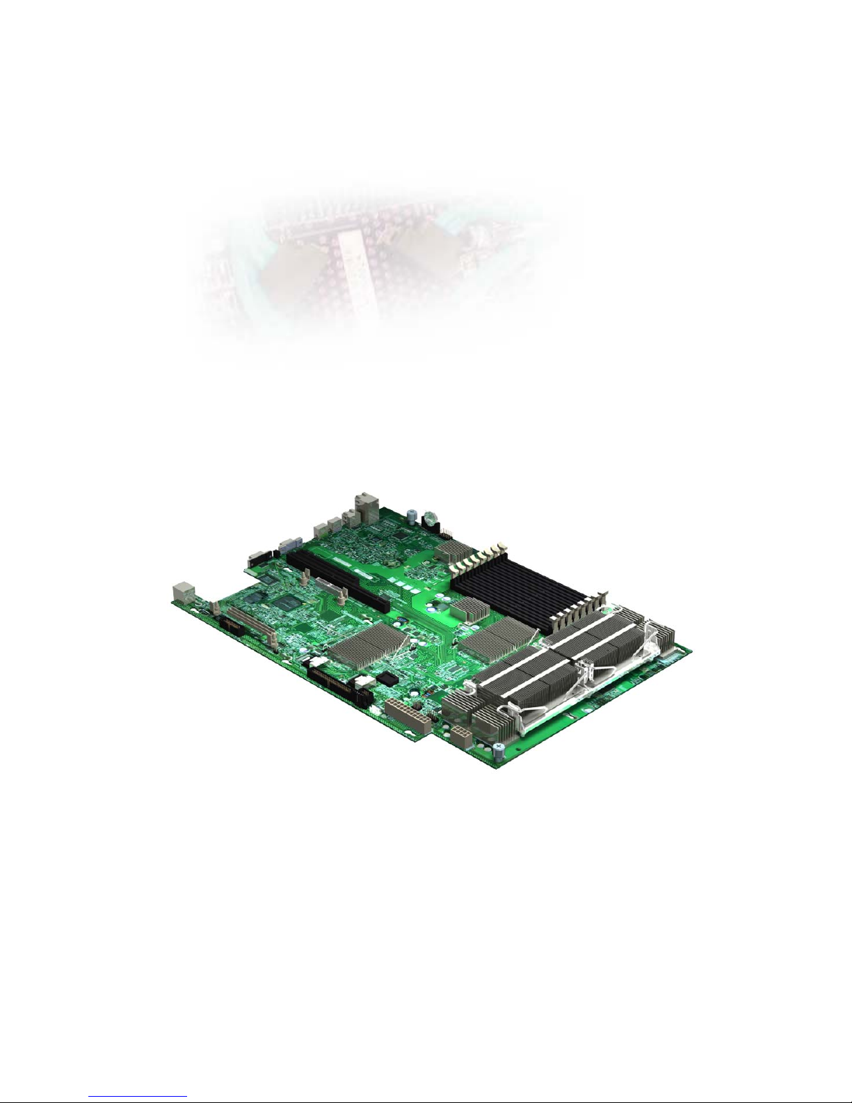
Figure 1-1 Motherboard Overview....................................................................................................1-2
Figure 1-2 Connectors and Component Locations............................................................................1-4
Figure 1-3 Back Panel Connectors....................................................................................................1-6
Figure 2-1 Screws Placement............................................................................................................2-2
Figure 2-2 Battery Location..............................................................................................................2-3
Figure 2-3 Pulling the Battery out of the Holder...............................................................................2-4
Figure 2-4 Putting the Battery into the Holder..................................................................................2-4
Figure 2-5 Processor Location ..........................................................................................................2-5
Figure 2-6 Pulling up the Two Levers...............................................................................................2-6
Figure 2-7 Lifting the Heat Sink up ..................................................................................................2-6
Figure 2-8 Pulling up the Two Levers...............................................................................................2-7
Figure 2-9 Placing the Heat Sink on Top of the Processor................................................................2-7
Figure 2-10 Locking the Two Levers................................................................................................2-7
Figure 2-11 Opening the Load Plate..................................................................................................2-8
Figure 2-12 Lifting the Processor out of the Socket..........................................................................2-8
Figure 2-13 Closing the Load Plate...................................................................................................2-8

Figure 2-14 Putting on the PnP Cap..................................................................................................2-9
Figure 2-15 Aiming the Golden Corner at the Socket.......................................................................2-9
Figure 2-16 Releasing the Screws...................................................................................................2-10
Figure 2-17 Lifting up the Heat Sink Socket...................................................................................2-10
Figure 2-18 Installing the Heat Sink Base Socket...........................................................................2-10
Figure 2-19 System Memory Location............................................................................................2-13
Figure 2-20 Lifting the DIMM out of the Socket............................................................................2-14
Figure 2-21 Pressing the Retaining Clips Outward.........................................................................2-14
Figure 2-22 Inserting the DIMM into the Socket............................................................................2-14
Figure 2-23 System Configuration Jumper Location......................................................................2-15
Figure 2-24 CPU FSB Clock Jumper Location...............................................................................2-15
Figure 3-1 Main Power Connector....................................................................................................3-1
Figure 3-2 Processor Power Connector.............................................................................................3-2
Figure 3-3 Front Panel IDE Connector .............................................................................................3-3
Figure 3-4 Floppy Connector............................................................................................................3-5
Figure 3-5 Internal USB Port for USB Floppy..................................................................................3-6
Figure 3-6 Chassis Intrusion Connector............................................................................................3-7
Figure 3-7 Front Panel VGA Connector............................................................................................3-8
Figure 3-8 D-sub VGA Port ..............................................................................................................3-9
Figure 3-9 Serial Port......................................................................................................................3-10
Figure 3-10 Keyboard Port..............................................................................................................3-11
Figure 3-11 Mouse Port...................................................................................................................3-12
Figure 3-12 Rear Dual USB Port ....................................................................................................3-13
Figure 3-13 Front Panel USB Connector ........................................................................................3-14
Figure 3-14 I2C (SMBus) Signal Connector for PSU......................................................................3-15
Figure 3-15 Dual NIC Connector (RJ45)........................................................................................3-16
Figure 3-16 Management Port (RJ45).............................................................................................3-16
Figure 3-17 Fan Power/Fan Tach Connector...................................................................................3-17
Figure 3-18 Mini-SAS Connector...................................................................................................3-18
Figure 3-19 LCM Connector...........................................................................................................3-19
Figure 3-20 System Configuration Jumper .....................................................................................3-20
Figure 3-21 CPU FSB Clock Jumper..............................................................................................3-21
L
Li
is
st
t
o
of
f
T
Ta
ab
bl
le
es
s
Table 1-1 Introduction of the Manual................................................................................................1-1
Table 1-2 Product Features................................................................................................................1-2
Table 2-1 Processor Information.......................................................................................................2-5
Table 2-2 DIMM Installation Option in Non-redundant Mode.......................................................2-11
Table 2-3 DIMM Installation Option in Mirrored Mode.................................................................2-12
Table 2-4 DIMM Installation Option in Sparing Mode...................................................................2-12
Table 3-1 Main Power Connector Pin Definition..............................................................................3-2
Table 3-2 Processor Power Connector Pin Definition.......................................................................3-2
Table 3-3 Front Panel IDE Connector Pin Definition .......................................................................3-3
Table 3-4 Floppy Connector Pin Definition......................................................................................3-5
Table of contents


