IFR T-1401 Instruction Manual

-~
ARTISAN
®
~I
TECHNOLOGY
GROUP
Your definitive source
for
quality
pre-owned
equipment.
Artisan Technology
Group
Full-service,
independent
repair
center
with
experienced
engineers
and
technicians
on staff.
We
buy
your
excess,
underutilized,
and
idle
equipment
along
with
credit
for
buybacks
and
trade-ins
.
Custom
engineering
so
your
equipment
works
exactly as
you
specify.
•
Critical
and
expedited
services
•
Leasing
/
Rentals/
Demos
• In
stock/
Ready-to-ship
•
!TAR-certified
secure
asset
solutions
Expert
team
ITrust
guarantee
I
100%
satisfaction
All
tr
ademarks,
br
a
nd
names, a
nd
br
a
nd
s a
pp
earing here
in
are
th
e property of
th
e
ir
r
es
pecti
ve
ow
ner
s.
Visit our website - Click HERE

OPERATION
eee
deshantine,
f
«
i
~
i
2
,
10200
West
York
Street/Wichita,Kansas
67215
U.S.A./(316)522-498
1/TWX910-741-6952
1002-7101-000°

1.
“3
~>-
OPERATION/MAINTENANCE
MANUAL
Li
W/ILLUSTRATED
PARTS
LIST
TACAN
TEST
SYSTEM
SECTION
1
~
DESCRIPTION
General
Description
and
Features
The
T-1401
is
a
TACAN
simulator
used
to
test
TACAN
receiver/transmitters.
It
_ts
designed
to be
used
with
an
ATC-1400A.
The
T-1401
can
be
operated
as
a
desk-top
unit
or
it
can
be
installed
in
a
rack.
All
test
controls
are
on
the
front
panel.
Those
on
the
rear
panel
are
usually
only
for
setup
(before
starting
a
test).
Usually,
the
T-1401
is
operated
and
controlled
via
the
ATC-
1400A
with
the
T-1401
mounted
on
top
of,
and
strapped
to,
the
ATC-1400A.
The
mode
of
operation
is
determined
primarily
by
control
settings
on
the
front
panel
of
the
T-1401.
In
the
absence
of
an
ATC-1400A,
the
T-1401
will
operate
with
X
Mode
pulse
spacing.
Identification
and
Equalizer
pulse
pairs
are
enabled
when
the
G/A
Mode
has
been
selected.
Mode
information
is
also
received
from
the
ATC-1400A
when
the
two
are
connected
via
the
IFR
Bus.
This—
information
includes
Identification
On/Off,
Equalizer
On/Off,
X/Y
Mode.
and
P1
to
P2
pulse
spacing
deviation.
The
T-1401
weighs
17.5
pounds
(7.95
kg)
and
is
16
7/8
inches
(42.86
cm)
wide,
16
inches
(40.64
cm)
deep
less
handles,
and
3
1/4
inches
(8.25
cm)
high.
See
figure
1.
Removal
of
the
“op
cover gives
access
to
three
PC
Board
Assemblies
(Analog,
Computer,
and
TACAN)
mated
with
connectors
on
the
Motherboard
PC
Board
Assembly.
The
Power
Supply
Assembly,
containing
two
PC
Board
Assem-
blies,
and
the
Line
Supply
Assembly
with
PC
Board
are
mounted
on
the
left
side
(viewed
from
the
front).
Two
PC
Board
Assemblies,
Switch
and
Display,
are
attached
to
the
back
of
the
front
panel.
Mode
of
operation
is
determined
by
switch
settings
on
the
front
panel.
Functional
Capabilities
The
T-1401/ATC-1400A
set
is
capable
of
complete
simulation
of
G/A
X,
G/A
Y,
A/A
X,
A/A
Y,
INVERSE
G/A
X,
INVERSE
G/A
Y,
INVERSE
A/A
X
and
INVERSE
A/A
Y
Modes
of
operation.
Nominal pulse
spacings,
modulation
signals
and
channel
pairings
are
automatically
selected
for
each
mode.
Convenient
front
panel
controls
give
a
continuous
display
of
each
parameter
of
the
TACAN
signal
and
provide
for
varying
each
parameter
from
its
nominal
value.
Channel
cross-references
are
given
in
Appendix
D.
For
a
complete
description
of
the
functional
capabilities,
refer
to
Section
3,
J=1=1
Page
1/2
Nov
16/87

“"_
OPERATION/MAINTENANCE
MANUAL
~W/ILLUSTRATED
PARTS
LIST
-M&
...TACAN
TEST
SYSTEM
These
specifications.
supersede
ATC-1400A
and
T-1401
“specifications
whenever
the
T-1401
is
mated
to
the
ATC-1400A.
Refer
to
Section
1-3-1
of
either
the
ATC-1400A
or
T-1401
.
Operation/Maintenance
Manual
(as
appropriate)
for
“specifications
not
listed
in
this
section.
~
°°"
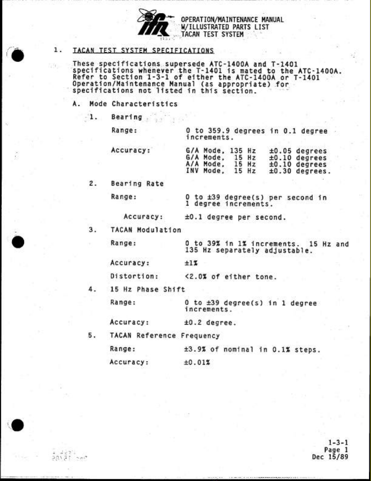
A.
Mode
Characteristics
“1.
Bearing.
1.7...
.
Range:
0
to
359.9
degrees
in
0.1
degree
increments.
Accuracy:
G/A
Mode,
135
Hz
£0.05
degrees
G/A
Mode,
15
Hz
+0.10
degrees
A/A
Mode,
15
Hz
+0.10
degrees
INV
Mode,
15
Hz
40.30
degrees.
2.
Bearing
Rate
Range:
0
to
+39
degree(s)
per
second
in
1
degree
increments.
Accuracy:
+t0.1
degree
per
second.
-
3.
TACAN
Modulation
@
Range:
0
to
39%
in
1%
increments.
15
Hz
and
135
Hz
separately
adjustable.
Accuracy:
£12
Distortion:
<2.0%
of
either
tone.
4,
15
Hz
Phase
Shift
Range:
0
to
+39
degree(s)
in
1
degree
increments.
Accuracy:
£0.2
degree.
5.
TACAN
Reference
Frequency
Range:
£3.9%
of
nominal
in
0.1%
steps.
Accuracy:
+0.01%
1-3-1
Le
Page
1
rage
Dec
15/89

j
"
:OPERATION/NAINTENANCE.
MANUAL
Gi
i.
-*-W/TLLUSTRATED
PARTS
LIST
“*<TACAN
TEST
SYSTEM
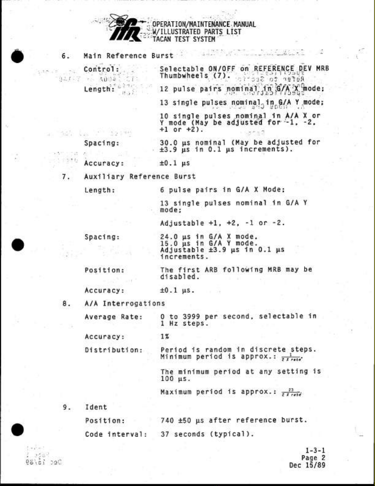
Main
Reference
Burst
-
BEE
a
ete
ede
_
Control:
..°
°
Selectable
ON/OFF
on
REFERENCE
DEV
MRB
Thumbwheels.
(7).
12
pulse
pairs
nominal
in
13
single
pulses
nominal.in
G/A
Y
mode;
na
ex
Snode:
PERG:
10
single
pulses
nominal
in
A/A
X.or
Y
mode
(May
be
adjusted
for“-1,
-2,
+1
or
+2).
a
Spacing:
30.0
ps
nominal
(May,
be
adjusted
for
-
+3.9
ps
in
0.1
ps
increments).
Accuracy:
+0.1
us
Auxiliary
Reference
Burst
Length:
6
pulse
pairs
in
G/A
X
Mode;
13
single
pulses
nominal
in
G/A
Y
mode;
Adjustable
+1,
+2,
-1
or
-2.
Spacing:
24.0
ps
in
G/A
X
mode,
15.0
ps
in
G/A
Y
mode.
Adjustable
+3.9
ws in
0.1
ps
increments.
Position:
The
first
ARB
Following
MRB
may
be
.
disabled.
Accuracy:
+0.1
ps.
A/A
Interrogations
Average
Rate:
0
to
3999
per
second,
selectable
in
1
Hz
steps.
Accuracy:
1%
Distribution:
Period
is
random
in
discrete
steps.
: .
.
.
. 1
Minimum
period
is
approx.
:
Ty
te
The
minimum
period
at
any
setting
is
100
us.
Maximum
period
is
approx.:
;%
2X
raté
Ident
Position:
740
+50
ps
after
reference
burst.
Code
interval:
37
seconds
(typical).
1-3-1
Page
2
Dec
15/89

—
-
OPERATION/MAINTENANCE
MANUAL
~.
W/
ILLUSTRATED
PARTS
LIST
Pe
~
TACAN
TEST
SYSTEM
“
f
.
‘@
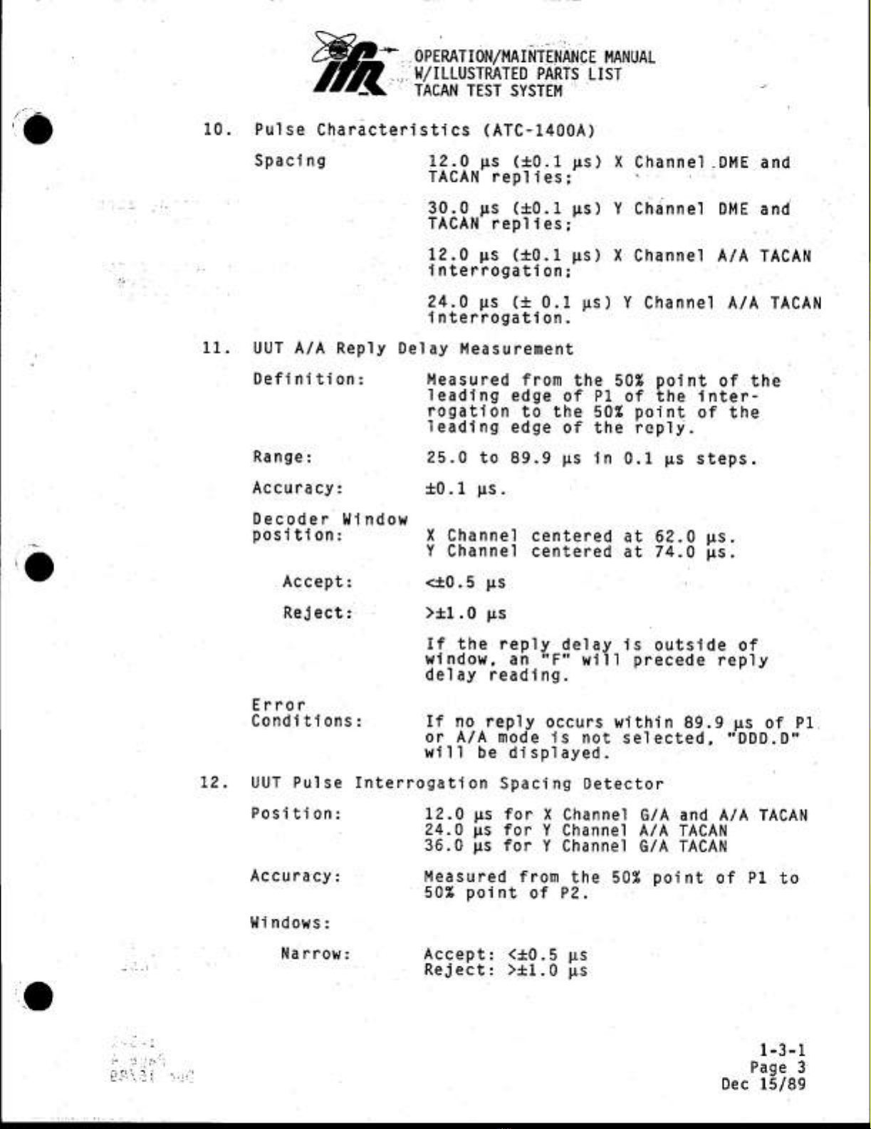
10.
Pulse
Characteristics
(ATC-1400A)
Spacing
12.0
ps
(40.1
ps)
X
Channel
-
-DME
and
TACAN
replies;
30.0
ps
(40.1
ps)
Y
Channel
DME
and
TACAN
replies;
12.0
ps
(40.1
ps)
X
Channel
A/A
TACAN
interrogation;
24.0
ps (+
0.1
ws)
Y
Channel
AIA
TACAN
interrogation.
11.
UUT A/A
Reply
Delay
Measurement
Definition:
Measured
from
the
50%
point
of
the
leading
edge
of
Pl
of
the
inter-
rogation
to
the 50%
point
of
the
leading
edge
of
the
reply.
Range:
25.0
to
89.9
ps
in
0.1
ws
steps.
Accuracy:
+0.1
ws.
Decoder
Window
position:
X
Channel
centered
at
62.0
us.
~
Y
Channel
centered
at
74.0
us.
|
@
Accept:
<t0.5
ps
Reject:
.
>+1.0
ps
If
the
reply delay
is
outside
of
window,
an
"F"
will
precede
reply
delay
reading.
Error
Conditions:
If
no
reply
occurs
within
89.9
us
of
Pl
or
A/A
mode
is
not
selected,
“DDD.
D"
will
be
displayed.
12.
UUT
Pulse
Interrogation
Spacing
Detector
Position:
12.0
ws
for
X
Channel
G/A
and
A/A
TACAN
24.0
ps
for
Y
Channel
A/A
TACAN
36.0
ws
for
Y
Channel
G/A
TACAN
Accuracy:
Measured
from
the 50%
point
of
Pl
to
50%
point
of
P2.
Windows:
Narrow:
Accept:
<1£0.5
us
cha
:
Reject:
>4+1.0
ps
ek
1-3-1
7
Page
3
Dec
15/89


*-
OPERATION/MAINTENANCE
MANUAL
Zi
Fa
~
W/ILLUSTRATED
PARTS
LIST
[Sm
TACAN
TEST
SYSTEM
2.
@
Wide:
‘13.
SCOPE
SYNC
15
Hz:
135
Hz:
MRB:
ARB:
A/A
INTERR:
INV
TACAN
Syne:
©
Polarity:
Width:
Accept:
<+£2.0
us
i
Reject:
>+3.0
us
‘
27.0
us
before
the
positive
going
zero
crossing
of
the
15
Hz
sine
wave
modulation.
2.5
ws
before
the
positive
going
zero
crossing
of
the
8th
135
Hz
sine
wave
modulation
after
the
15
Hz
positive
going
zero
crossing.
3.0
us
before
the
first
pulse
of
the
Main
Reference
Burst.
3.0
ws
before
the
first pulse
of
each
Auxiliary
Reference
Burst.
3.0
ps
before
the
first
pulse
of
each
A/A
Interrogation
pulse
pair.
Leading
Edge
is
coincident
with
negative
going
zero
crossing
of
the
15
Hz
sine
wave
with
180
degrees
bearing
selected.
Internally
selectable,
standard
setting
is
negative.
70
ps
(418.0
ws)
14.
External
Interrogations
J10010
Enable:
Polarity:
Level:
J10011
TRIGGER:
Polarity:
Level:
B.
Power
Characteristics
AC
Input:
Enables
J10011..
and
gates
off
all
other
interrogations
including reference
bursts
and
Ident
pairs”
as
long
as
ENABLE
is
active.
Active
low
TTL
Triggers
modulator
when
enabled
by
J10010.
Negative
edge
TTL
105
to
120
VAC
or
210
to
250
VAC,
50
to
400
Hz,
power
consumption
is
Tess
than
150
watts.
1-3-1
Page
4
Dec
15/89

on
~
OPERATION/MAINTENANCE
MANUAL
Zi
W/ILLUSTRATED
PARTS
LIST
TACAN
TEST
SYSTEM
WARNING:
HIGH
VOLTAGE
EQUIPMENT
THIS
EQUIPMENT
CONTAINS
CERTAIN
CIRCUITS
AND/OR
COMPONENTS
OF
EXTREMELY
HIGH
VOLTAGE
POTENTIALS,
CAPABLE
OF
CAUSING
SERIOUS
BODILY
INJURY
OR
DEATH.
WHEN
PERFORMING
ANY
OF
THE
PROCEDURES
CONTAINED
IN
THIS
MANUAL,
HEED
ALL
APPLICABLE
SAFETY
PRECAUTIONS.
RESCUE
OF
SHOCK
VICTIMS
-
DO
NOT
ATTEMPT
TO
PULL
OR
GRAB
THE
VICTIM
2. IF
POSSIBLE,
TURN
OFF
THE
ELECTRICAL
POWER.
3.
IF
YOU
CANNOT
TURN
OFF
ELECTRICAL
POWER,
PUSH,
PULL
OR
LIFT
THE
VICTIM
TO
SAFETY
USING
A
WOODEN
POLE,
A
ROPE
OR
SOME
OTHER
DRY
INSULATING
MATERIAL.
FIRST
AID
.
AS
SOON
AS
VICTIM
IS
FREE
OF
CONTACT
WITH
SOURCE
OF
ELECTRICAL
SHOCK,
MOVE
VICTIM
A
SHORT
DISTANCE
AWAY
FROM
SHOCK
HAZARD.
2.
SEND
FOR
DOCTOR
AND/OR
AMBULANCE.
3.
KEEP
VICTIM
WARM,
QUIET
AND
FLAT
ON
HIS/HER
BACK.
.
IF
BREATHING
HAS
STOPPED
,
ADMINISTER
ARTIFICIAL
RESUSCITATION.
STOP
ALL
SERIOUS
BLEEDING.
>
OPERATION/MAINTENANCE
MANUAL
Li
W/ILLUSTRATED
PARTS
LIST
TACAN
TEST
SYSTEM
CAUTION}
INTEGRATED
CIRCUITS
AND
SOLID STATE
DEVICES
SUCH
AS
MOS
FET'S,
ESPECIALLY
CMOS
TYPES,
ARE
SUSCEPTIBLE
TO
DAMAGE
BY
ELECTROSTATIC
DISCHARGES
RECEIVED
FROM
IMPROPER
HANDLING,
THE
USE
OF
UNGROUNDED
TOOLS,
AND
IMPROPER
STORAGE
AND
PACKAGING.
ANY
MAINTENANCE
TO
THIS
UNIT
MUST
BE
PERFORMED
WITH
THE
FOLLOWING
PRECAUTIONS
:
1.
BEFORE
USING
IN
A
CIRCUIT,
KEEP
ALL
LEADS
SHORTED
TOGETHER
EITHER
BY
THE USE
OF
VENDOR-
SUPPLIED
SHORTING
SPRINGS
OR
BY
INSERTING
LEADS
INTO
A
CONDUCTIVE
MATERIAL.
2.
WHEN
REMOVING
DEVICES
FROM
THEIR
CONTAINERS,
GROUND
THE
HAND
BEING
USED
WITH
A
CONDUCTIVE
WRISTBAND.
3.
TIPS
OF
SOLDERING
IRONS
AND/OR
ANY
TOOLS
USED
MUST
BE
GROUNDED.
4.
DEVICES
MUST
NEVER
BE
INSERTED
INTO
NOR
REMOVED
FROM
CIRCUITS
WITH
POWER
ON.
5.
PG
BOARDS,
WHEN
TAKEN
OUT
OF
THE
SET,
MUST
BE
LAID
ON
A
GROUNDED
CONDUCTIVE
MAT
OR
STORED
IN
A
CONDUCTIVE
STORAGE
BAG.
INOTE}
Remove
any
built-in
power
source,
such
as
a
battery,
before
laying
PC
Boards
on
conductive
mat
or
storing
in
conductive
bag.
6.
PC
BOARDS,
IF
BEING
SHIPPED
TO
THE
FACTORY
FOR
REPAIR,
MUST
BE
PACKAGED
IN
A
CONDUCTIVE
BAG
AND
PLACED
IN
A
WELL-CUSHIONED
SHIPPING
BOX.
THE
USE
OF
SIGNAL
GENERATORS
FOR
MAINTENANCE
AND
OTHER
ACTIVITIES
CAN
BE
A
SOURCE
OF
ELECTROMAGNETIC
INTERFERENCE
TO
COMMUNICATION
RECEIVERS,
WHICH
CAN
CAUSE
DISRUPTION
AND
INTERFERENCE
TO
COMMUNICATION
SERVICE
OUT
TO
A
DISTANCE
OF
SEVERAL
MILES.
USERS
OF
THIS
EQUIPMENT
SHOULD
SCRUTINIZE
ANY
OPERATION
WHICH
RESULTS
IN
RADIATION
OF
A
SIGNAL
(DIRECTLY
OR
INDIRECTLY)
AND
SHOULD
TAKE
NECESSARY
PRECAUTIONS
TO
AVOID
POTENTIAL
COMMUNICATION
INTERFERENCE
PROBLEMS.
i
-—
OPERATION/MAINTENANCE
MANUAL
y/
W/ILLUSTRATED
PARTS
LIST
TACAN
TEST
SYSTEM
————_
RECORD
OF
REVISIONS
———————————
ol
REV
ISSUE
DATE
BY
REV
ISSUE
DATE
BY
NO
DATE
INSR
NO
DATE
INSR

Cag
~-
OPERATION/MAINTENANCE
MANUAL
W/ILLUSTRATED
PARTS
LIST
TACAN
TEST
SYSTEM
JR
Title
Page
Copyright
Page
Warning
Page
Caution
Page
Record
of
Revisions
Page
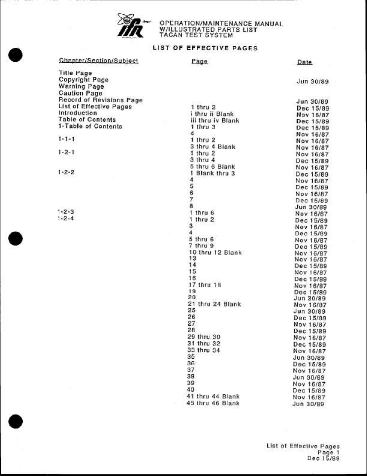
List
of
Effective
Pages
Introduction
Table
of
Contents
1-Table
of
Contents
1-1-1
1-2-1
1-2-2
LIST
OF
EFFECTIVE
PAGES
Page
1
thru
2
i
thru
fi
Blank
iii
thru
iv
Blank
1
thru
3
4
1
thru
2
3
thru
4
Blank
1
thru
2
3
thru
4
5
thru
6
Blank
1
Blank
thru
3
AWA
ONIMOAA
5
thru
6
7
thru
9
10
thru
12
Blank
1
21
thru
24
Blank
29
thru
30
31
thru
32
33
thru
34
40
41
thru
44
Blank
45
thru
46
Blank
Date
Jun
30/89
Jun
30/89
Dec
15/89
Nov
16/87
Dec
15/89
Dec
15/89
Nov
16/87
Nov
16/87
Nov
16/87
Nov
16/87
Dec
15/89
Nov
16/87
Dec
15/89
Nov
16/87
Dec
15/89
Nov
16/87
Dec
15/89
Jun
30/89
Nov
16/87
Dec
15/89
Nov
16/87
Dec
15/89
Nov
16/87
Dec
15/89
Nov
16/87
Nov
16/87
Dec
15/89
Nov
16/87
Dec
15/89
Nov
16/87
Dec
15/89
Jun
30/89
Nov
16/87
Jun
30/89
Dec
15/89
Nov
16/87
Dec
15/89
Nov
16/87
Dec
15/89
Nov
16/87
Jun
30/89
Dec
15/89
Nov
16/87
Jun
30/89
Nov
16/87
Dec
15/89
Nov
16/87
Jun
30/89
List
of
Effective
Pages
Page
1
Dec
15/89

W/ILLUSTRATED
PARTS
LIST
TACAN
TEST
SYSTEM
1-2-5
1
thru
8
Dec
15/89
9
thru
10
Jun
30/89
11
Dec
15/89
12
thru
15
Jun
30
89
16
Dec
15/89
17
Jun
30/89
18
thru
20
Blank
Dec
15/89
1-2-6
1
thru
2
Blank
Dec
15/89
1-3-1
1
thru
4
Dec
15/89
1-4-1
1
thru
2
Nov
16/87
1-5-1
1
thru
2
Blank
Nov
16/87
2-Table
of
Contents
1
thru
4
Blank
Nov
16/87
2-1-1
1
thru
4
Blank
Nov
16/87
2-2-1
1
Nov
16/87
2
Dec
15/89
3
thru
4
Blank
Nov
16/87
5
thru
8
Blank
Nov
16/87
9
thru
12
Blank
Nov
16/87
13
Dec
15/89
14
Jun
30/89
15
Dec
15/89
16
thru
18
Aug
28/87
19
thru
20
Blank
Nov
16/87
21
Nov
16/87
22
Dec
15/89
23
thru 24
Blank
Jun
30/89
25
Dec
15/89
26
thru
27
Nov
16/87
28
thru
29
Dec
15/89
©
30
Nov
16/87
31
thru
32
Blank
Jun
30/89
2-2-2
1
thru
7
Nov
16/87
8
thru
9
Blank
Dec
15/89
10
thru
13
Nov
16/87
14
Dec
15/89
2-2-3
1
Nov
16/87
2
thru
3
Jun
30/89
4
thru
14
Nov
16/87
15
Dec
15/89
16
thru
20
Nov
16/87
21
thru
24
Dec
15/89
3-Table
of
Contents
1
thru
2
Blank
Dec
15/89
4-Table
of
Contents
1
thru
2
Blank
Nov
16/87
4-1
1
thru
16
Nov
16/87
4-2
1
thru
13
Blank
Nov
16/87
14
thru
17
Blank
Nov
16/87
18
thru
31
Blank
Nov
16/87
32
thru
36
Blank
Nov
16/87
37
thru
42
Blank
Nov
16/87
4-3
1
thru
8
Nov
16/87
4-4
1
thru
4
Nov
16/87
Appendix
A
1
thru
4
Blank
Nov
16/87
Appendix
B
1
thru
2
Blank
Nov
16/87
Appendix
C
1
thru
8
Blank
Nov
16/87
Appendix
D
1
thru
8
Blank
Nov
16/87
Appendix
E
1
thru
2
Blank
Dec
15/89
a
=~
OPERATION/MAINTENANCE
MANUAL
List
of
Effective
Pages
Page
2
Dec
15/89

OPERATION/MAINTENANCE
MANUAL
W/ILLUSTRATED
PARTS
LIST
TACAN
TEST
SYSTEM
INTRODUCTION
-
TACAN
TEST
SYSTEM
This
manual
contains
instructions
for
operating
and
maintaining
the
Tacan
Test
System,
which
is
composed
of
the
T-1401
and
ATC-1400A,
and
is
to
be
used
in
con-
junction
with
the
ATC-1400A
Operation/Maintenance
Manual.
It
fis
recommended
that
the
operator
and
maintenance
technicians
be
familiar
with
the
Description
of
Controls,
1-2-2,
and
Troubleshooting,
2-2-1,
before
operating
or
performing
maintenance
on
the
equipment.
The
T-1401
simulates
all
the
parameters
of
a
TACAN
modulation
signal
necessary
to
test
TACAN
receiver/transmitters.
It
is
designed
to be
used
with
an
ATC-1400A.
The
T-1401
can
be
operated
as
a
bench-top
unit
or
it
can
be
installed
in
a
rack.
The
contents
of
the
manual
are
in
three
chapters:
Operation,
Maintenance,
and
illustrated
Parts List.
There
are
four
appendices.
NOTE:
Throughout
the
text,
all
controls,
indicators
and
connectors
are
iden-
tified
by
parenthesized
item
numbers.
These.
numbers
correspond
to
item
numbers
in
the
following
figures:
Figures
3
and
4
of
1-2-2,
T-1401
Front
and
Rear
Panel
Controls
and
Indicators
and
Figure
6
of
1-2-2,
ATC-1400A
Front
and
Rear
Panels
(See
ATC-1400A
Operation/Maintenance
Manual).
INTRODUCTION
Page
i/ii
Nov
16/87
Table of contents
Popular Marine Radio manuals by other brands


vesper marine
vesper marine WatchMate Vision install guide

Siemens
Siemens SIMATIC RF645T Compact operating instructions

Texas Instruments
Texas Instruments TIRIS RI-TRP-RRHP Reference manual

Uniden
Uniden UM525 owner's manual

Ocean Signal
Ocean Signal Safe Sea S100 user manual

KAPSCH
KAPSCH G4 Mounting instructions