Texas Instruments TIRIS RI-TRP-RRHP User manual

Texas Instruments
Registration
and
Identification
System
23 mm Glass Encapsulated
Transponder
RI-TRP-RRHP
RI-TRP-WRHP
Reference Manual
11-09-21-023 25-July-1996

23 mm Transponder Reference Manual 25 July 1996
Page 2of 22
Edition Notice: Fourth Edition - July 1996
This is the fourth edition of this manual, it describes the following transponders:
RI-TRP-RRHP
RI-TRP-WRHP
This Reference Manual is for customers who wish to use the TIRIS 23 mm Glass Encapsulated
Transponder in Radio Frequency Identification (RFID) installations. The manual includes
technical information concerning the function, technical specifications, application and
environmental related data.
Texas Instruments reserves the right to change its products or services at any time without
notice. TI provides customer assistance in various technical areas, but does not have full
access to data concerning the uses and applications of customer's products. Therefore TI
assumes no responsibility for customer product design or for infringement of patents and/or
the rights of third parties, which may result from assistance provided by TI.
The TIRIS logo and the word TIRIS are registered trademarks of Texas Instruments
Incorporated.
Copyright 1996 Texas Instruments Incorporated.
All rights reserved.

25 July 1996 23 mm Transponder Reference Manual
Page 3of 22
Contents
1. Introduction ................................................................................................................................... 4
2. Transponder Packaging ................................................................................................................. 5
3. Product Codes ............................................................................................................................... 5
4. Function ........................................................................................................................................ 5
4.1 Read (Reading of RO and R/W Transponders) ........................................................................ 5
4.2 Write and Program .................................................................................................................. 8
5. Characteristics of the Pulsed FM System ....................................................................................... 9
5.1 Basic System Data ................................................................................................................... 9
5.2 Reader and System Design Impact .......................................................................................... 10
5.3 System Performance and Functional Reliability Impact ........................................................... 10
5.4 Other Quality Factors of the TIRIS Pulsed FM System ............................................................ 10
6. EMI/EMC Performance ................................................................................................................. 11
6.1 General ................................................................................................................................... 11
6.2 The Automotive Environment and Factors .............................................................................. 11
6.3 TIRIS Pulsed FM Transponder and System Performance ......................................................... 11
7. Measurement Set-Ups .................................................................................................................... 14
7.1 Measurement set-up: Resonance frequency, bandwidth, quality factor ..................................... 14
7.2 Measurement Set-Up: Powering Field Strength ....................................................................... 15
7.3 Measurement set-up: Transponder Signal Strength ................................................................. 17
8. Absolute Maximum Ratings .......................................................................................................... 18
9. Recommended Operating Conditions ............................................................................................. 18
10. Characteristics ............................................................................................................................. 19
11. Environmental Data and Reliability ............................................................................................. 20
12. Memory ....................................................................................................................................... 20
13. Package ....................................................................................................................................... 20
14. Packing Symbolization ................................................................................................................ 21
Appendix A: Conversion Formula ...................................................................................................... 22
Figures
Figure 1: System Configuration Showing the Reader, Antenna and Transponder ................................ 4
Figure 2: Block Diagram of the TIRIS Pulsed FM Transponder .......................................................... 4
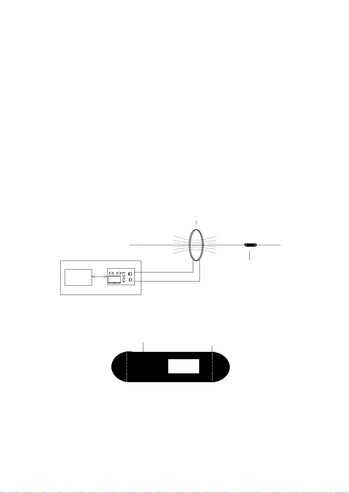
Figure 3: Dimensions of the TIRIS 23 mm Transponder (in mm) ....................................................... 5
Figure 4: Charge and Read Function of the Transponder .................................................................... 6
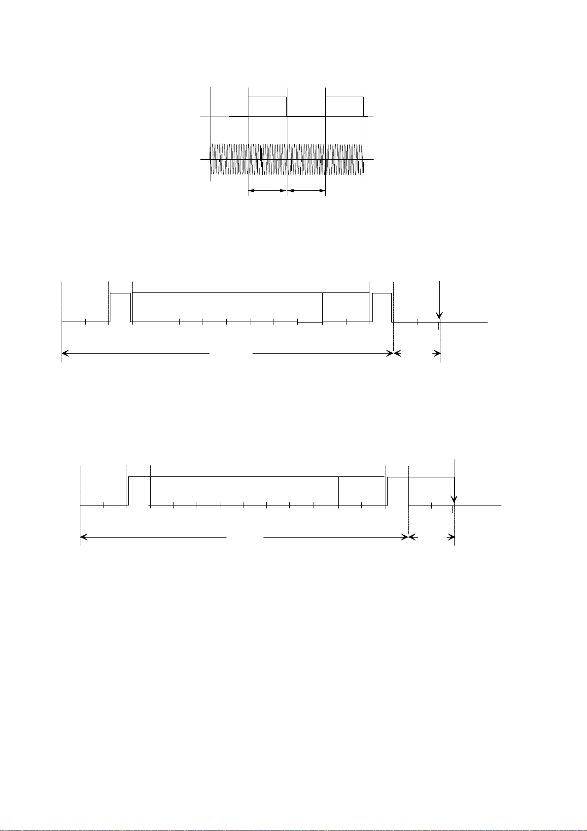
Figure 5: FM Principle Used for the Read Function of TIRIS Transponders ........................................ 7
Figure 6a: Read Data Format of TIRIS RO Transponder ..................................................................... 7
Figure 6b: Read Data Format of TIRIS R/W Transponder ................................................................... 7
Figure 7: Charge, Write and Program Principle used for TIRIS .......................................................... 8
Figure 8: The Write and Program Function ........................................................................................ 9
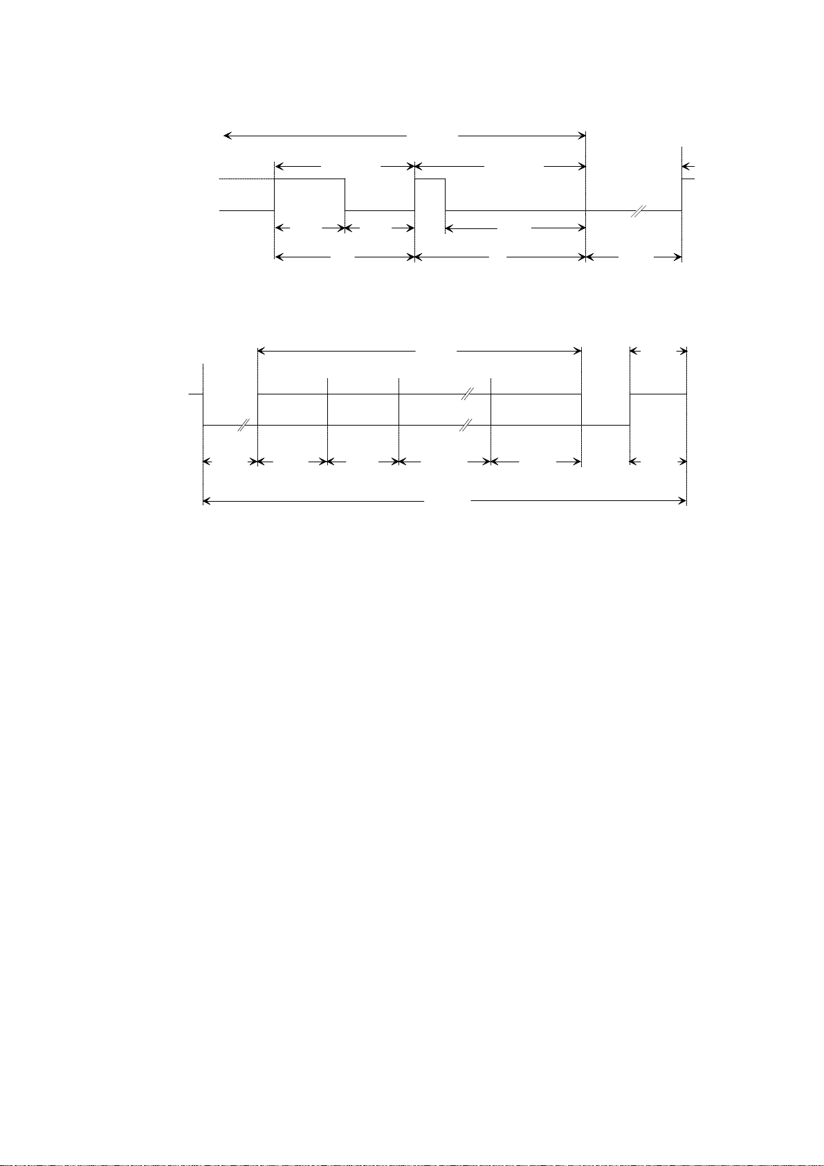
Figure 9: Write Data Format for Programming Function .................................................................... 9
Figure 10: EMI Performance Test of the TIRIS System. ..................................................................... 12
Figure 11: EMI performance in automotive environment. ................................................................... 13
Figure 12: Reading range under broad band noise (white noise) conditions ........................................ 13
Figure 13: Measurement for transponder resonance, bandwidth & quality factor ............................... 14
Figure 14: Determination of resonance and -3dB by monitoring pick-up coil voltage .......................... 15
Figure 15: Test set-up for powering field strength determination ........................................................ 15
Figure 16: Received signal at the pick up coil, if power field strength is sufficient .............................. 16
Figure 17: Determination of the transponder signal strength with Helmholtz aperture ........................ 17
Figure 18: Monitored signal voltage at the spectrum analyzer (time domain mode) ............................ 17

23 mm Transponder Reference Manual 25 July 1996
Page 4of 22
1. Introduction
The TIRIS 23 mm Glass Encapsulated Pulsed FM Transponder is a key product in low frequency
RFID systems that can be used for a variety of applications, such as automotive security systems.
The device is available in Read Only (RO) and Read/Write (R/W) versions. Electro Magnetic
signals are used to power the passive (batteryless) device, to transmit the identification number to
a reader unit or to program the device with new data. The basic principle is described in Figure 1.
Both RO and R/W versions use an 80 bit non-volatile memory (EEPROM) for storage of 64
identification bits and a 16 bit Block Check Character (BCC). The RO type is factory
programmed with a unique tamperproof code that cannot be altered. The R/W version can be
programmed by the user.
The 23 mm Transponder comprises a ferrite core antenna, a charge capacitor, a resonance
capacitor and the integrated circuit (Figure 2). The antenna inductance and the resonance
capacitor form a high quality resonant circuit.
CF45538
RFMODULE
FIELDLINES
CONTROL
UNIT
TIRISREAD/WRITEUNIT
ANTENNAAXIS
TRANSMIT/RECEIVE ANTENNA
TRANSPONDER
Figure 1: System Configuration Showing the Reader, Antenna and Transponder
CHARGE
CAPACITOR
ANTENNA
TRANSPONDER
IC
Figure 2: Block Diagram of the TIRIS Pulsed FM Transponder

25 July 1996 23 mm Transponder Reference Manual
Page 5of 22
2. Transponder Packaging
The dimensions of the transponder are given in Figure 3.
The 23 mm shape offers several advantages:
1. The transponder is hermetically sealed.
2. The transponder is robustly constructed to withstand vibration (IEC68-2-6) and shock
(IEC68-2-6).
3. For Applications where read range is not the most critical point the transponder can be
mounted or used in such a way that the orientation is not controlled.
Figure 3: Dimensions of the TIRIS 23 mm Transponder (in mm)
3. Product Codes
64 bit Read Only device: RI-TRP-RRHP
64 bit Read/Write device: RI-TRP-WRHP
4. Function
The Pulsed FM System uses a sequential function principle separating the transponder powering
(charge) and transponder data transmission mode. The advantages of the sequential mode are
described in Section 5.1 "Basic System Data".
4.1 Read (Reading of RO and R/W Transponders)
During the charge (or powering phase) of between 15 and 50 ms the interrogator generates an
electromagnetic field using a frequency of 134.2 kHz. The resonant circuit of the transponder is
energized and the induced voltage is rectified by the integrated circuit to charge the capacitor.
The transponder detects the end of the charge burst and transmits its data using Frequency Shift
Keying (FSK), utilizing the energy stored in the capacitor.

23 mm Transponder Reference Manual 25 July 1996
Page 6of 22
The typical data low bit frequency is 134.2 kHz, the typical data high bit frequency is 123.2 kHz.
The low and high bits have different durations, because each bit takes 16 RF cycles to transmit.
The high bit has a typical duration of 130 µs, the low bit of 119 µs. Figure 5 shows the FM
principle used. Regardless of the number of low and high bits, the transponder response duration
is always less than 20 ms.
The data format consists of 128 bits. Different start/stop bytes and end bits are used, to allow
secure distinction between RO and R/W Transponder. Figures 6a and 6b show the format of the
received data for RO and R/W transponders.
After transmission of the data format the capacitor is discharged. The typical transponder readout
timing is described in figure 4. The charge phase is followed directly by the read phase (RO
mode).
Data encoding is done in NRZ mode (Non Return to Zero). The clock is derived from the RF
carrier by a divide-by-16 function.
Figure 4: Charge and Read Function of the Transponder, Showing the Voltage at the
Transponder and Exciter (Reader) Coil

25 July 1996 23 mm Transponder Reference Manual
Page 7of 22
134.2 kHz 123.2 kHz 134.2 kHz 123.2 kHz
0 0 11
129.2 µs 119.9 µs
Figure 5: FM Principle Used for the Read Function of TIRIS Transponders
16 8 64
112 bits 16 bits
8
16 15
BITS
READ DATA
IDENTIFICATION DATA DATA
BCC END
BITS
DISCHARGE
MSBLSB
PRE
STOPSTART
Figure 6a: Read Data Format of TIRIS RO Transponder
16 8 64
112 bits 16 bits
816 15
BITS
READ DATA
IDENTIFICATION DATA DATA
BCC
MSBLSB
PRE
STOP
START
IDENT.
DATA
DISCHARGE
ENDBITS
Figure 6b: Read Data Format of TIRIS R/W Transponder

23 mm Transponder Reference Manual 25 July 1996
Page 8of 22
4.2 Write and Program
A new identification number can be written (programmed) into a R/W transponders in the following
manner: After the charge phase the R/W transponder enters the write mode providing the reader starts to
modulate the field by switching the transmitter on and off (TXCT-). Modulation index of this amplitude
modulation is 100%. The duration of the off-phase defines whether a low bit or a high bit is being
transmitted (Pulse Width Modulation). Writing means, the transponder shifts the received bits into a shift
register. After the write phase the reader's transmitter is switched on for a certain time (programming
time) in order to energize the process of programming the shift register data into the EEPROM. All 80
bits are programmed simultaneously into the EEPROM. Once the data is programmed into the EEPROM
the transponder automatically sends back the captured data to the reader to allow a security check, this
process takes place when the transmitter is switched off. Each read unit can be used as a write unit
through software change only. No hardware changes are required.
Figure 7 describes the write function by showing the transmitter (reader) RF output signal and the
transponder RF input signal. Figure 8 shows the TXCT- signal of the reader (transmitter) during the
write and program function. The data transmission format of the write mode is described in figure 9.
Charge: Continuous RF Module Transmitter output Signal
Write: Pulse width modulation of the RF module transmitter output signal
Program: Continuous RF module transmitter output signal
Read: Frequency Shift Keying of the transponder resonant circuit oscillation
Figure 7: Charge, Write and Program Principle used for TIRIS, showing the voltage at the
exciter (reader) and transponder antenna coil

25 July 1996 23 mm Transponder Reference Manual
Page 9of 22
TRANSMITTER OFF
TXCT -
HIGH BIT PROGRAM
WRITE
LOW BIT
TRANSMITTER ON toffH tonH toffL tonL
tprog
tHtL
Figure 8: The Write and Program Function
RF MODULE
TXCT- SIGNAL READ
20 ms
CHARGE
50 ms
KEYWORD
16
16 ms 160 ms 32 ms
PROGR.
15 ms
PASSWORD
16 ms
112 bit
309 ms
WRITE
WRITE DATA
128 bit
LSB MSB
WRITE FRAME
8 80
8
WRITE
Figure 9: Write Data Format for Programming Function
5. Characteristics of the Pulsed FM System
5.1 Basic System Data
The TIRIS Pulsed FM system multiplexes the power and read functions avoiding compromises.
This results in the following characteristics and options:
a) Individual optimization of the power and read functions by the system designer.
b) Variation of powering time by S/W to trade-off speed/current consumption with other
parameters
c) Absence of the high powering signal during the data reception phase
d) Data transmission by an active oscillator. This is associated with a high signal strength
level and a high transponder efficiency.
e) NRZ modulation encoding for high data speed and low transmission bandwidth.

23 mm Transponder Reference Manual 25 July 1996
Page 10 of 22
5.2 Reader and System Design Impact
*Ease of receiver and power function design and the optimization of performance due to
sequential power/read functions.
*Low field strength for transponder charge, resulting in lower cost of the power function.
*Optional performance and cost trade-offs by variation of:
interrogation speed by software down to 35 ms.
component selection to achieve different EMI performance levels.
5.3 System Performance and Functional Reliability Impact
*Inherent EMI robustness and high system Signal/Noise ratio because:
A. The transponder emits 6..20 dB higher data signal (compared to conventional systems).
B. The powering phase is noise immune and the data transmission phase duration is typically
16 ms.
C. FSK and NRZ allow a high data rate (typically 9 kbit/s).
D. Modulation is direct carrier FSK which has inherent AM noise suppression.
*Low reader power dissipation because of low charge field strength.
*Low power consumption due to pulsed operation (=low peak power x low duty cycle).
*Data telegram transmission is secured by 16 bit CRC-CCITT error detection protocol.
*The receive time is short, because the transponder protocol always starts at the beginning of
the data stream. Therefore read repetitions are not necessary.
5.4 Other Quality Factors of the TIRIS Pulsed FM System
*High and consistent transponder product quality and performance by automated high volume
manufacturing.
*The direct FSK provides enhanced separation and better position-selective reading of adjacent
transponders compared to AM systems.
*Product migration path concept from RO to R/W to Password protected and Multipage
transponders. The reader or system can be changed from RO to R/W by S/W change only.
*TIRIS transponders are 100% tested according to the procedures of TI's Total Quality
Culture.
*The reliability of TIRIS transponders is monitored through the following tests: temperature
and humidity, thermal shock, and operating life.

25 July 1996 23 mm Transponder Reference Manual
Page 11 of 22
6. EMI/EMC Performance
6.1 General
For any given RF-ID system, the EMI/EMC performance is determined by three factors:
1. The reader design and the resulting noise immunity performance
2. The signal strength of the transponder and Signal/Noise ratio at the receiver input
3. The transponder immunity to EM fields:
-The most critical EMI factor or component in a system is the reader immunity.
-A high transponder data signal facilitates reader design through the higher Signal/Noise.
ratio
-The least critical component is the transponder. Immunity levels are generally very high.
All EMI sources can be classified into three different categories:
a. Broad band "industrial" noise of sporadic or continuous nature
b. Discrete radio frequency signals unmodulated or FM /FSK modulated
c. Discrete radio frequency signals which are AM or ASK modulated.
6.2 The Automotive Environment and Factors
In an automotive environment all noise types are present and potentially cause EMI problems.
Especially the increased application of electronics and communication systems in cars employing
digital and ASK type modulation techniques can produce and emit high field strength levels.
The highest energy noise sources are in the low frequency part of the spectrum at frequencies
from a few cycles up to a few kHz. The sources are actuators, solenoid switching, ignition,
motors, control circuitry and so on. They pollute the car environment, either by direct emission,
or by induction, or by conducted radiation.
Above 10 kHz, the noise levels decay quickly at a rate of 20...40 dB/octave. RFID systems
emitting and receiving data signals at these or higher frequencies are less affected by EMI.
6.3 TIRIS Pulsed FM Transponder and System Performance
EMI measurement procedures which are most currently cited (for example the DIN 40839/part4)
are inappropriate to:
a. determine a realistic RF-ID system behavior for an automotive environment
b. determine the EMI performance and threshold of transponder
c. test systems at worst case (low frequency) conditions.
However the TIRIS transponder meets and exceeds the DIN40839/part4.

23 mm Transponder Reference Manual 25 July 1996
Page 12 of 22
The TIRIS system performance using reader and 23 mm transponder is shown in figures 10, 11
and 12.
Figure 10 shows the system immunity over a spectrum of 6 decades. At the most critical Radio
Short Wave Broadcast frequencies 400 V/m were encountered.
Figure 11 highlights the system performance simulating in-car RF communication conditions.
Figure 12 shows the performance (reading range) under induced broad band noise (white noise)
conditions.
Pulsed FM EMI System Performance
0.001 0.01 0.1 110 100 1,000
0.001
0.01
0.1
1
10
100
1,000
10,000
E M I FIELD STRENGTH
[VOLTS/m]
FREQUENCY MHz]
LW SW
MW FM VHF / UHF
Malfunction
Function Function
Figure 10: EMI Performance Test of the TIRIS System.
The graph shows the EM Immunity level in V/m as function of the frequency range from 1 kHz to
1000 MHz. Measurement condition: minimum 90% read probability at maximum read range.
Using a standard TIRIS reader.

25 July 1996 23 mm Transponder Reference Manual
Page 13 of 22
1 2 5 10 20 50 100 200 500 1,000
0
20
40
60
80
100
120
ELECTRICAL FIELD STRENGTH (VOLTS/m)
430
MHz 145
MHz
900
MHz
READING RANGE (%)
normalized
Figure 11: EMI performance at commonly used radio communication frequencies in
automotive environment.
White noise performance of TIRIS
20 25 30 35 40 45 50 55 60 65
0
10
20
30
40
50
60
70
80
90
100
NOISE LEVEL [dBµΑµΑ/m]
READING RANGE [%]
AM Systems
TIRIS Pulsed FM
Figure 12: Reading range under broad band noise (white noise) conditions

23 mm Transponder Reference Manual 25 July 1996
Page 14 of 22
7. Measurement Set-Ups
This Section describes typical measurement set-ups to determine transponder relevant data like:
resonant frequency, bandwidth, quality factor, powering field strength and transponder signal field
strength listed in Section 9 "Rocommended Operating Conditions".
7.1 Measurement Set-Up: Resonance frequency, bandwidth, quality factor of transponder
This test set-up is suitable for resonant frequency (fres) measurements as well as the determination
of the -3dB bandwidth (∆f) of the transponder. The quality factor Q of the transponder resonance
circuit can be calculated with equation (1):
(1) Q
f
f
res
=∆
The wires of the pick-up coil should be very thin to avoid influence on the measurement results (for
example: by damping). The choice of a 1 MΩinput resistor at the spectrum analyzer is
recommended. Figure 13 shows the test set-up. The relation between pick-up coil voltage and
frequency is shown in Figure 14.
PICK-UP
COIL
SPECTRUM
ANALYZER
COIL
INPUT
TRACKINGGENERATOR
TRANSPONDER
Figure 13: Measurement set-up for the determination of transponder resonance frequency,
bandwidth and quality factor

25 July 1996 23 mm Transponder Reference Manual
Page 15 of 22
3 dB
fRes f
UPick-up
coil
f
Figure 14: Determination of the resonance frequency and -3dB bandwidth by monitoring
the pick-up coil voltage
7.2 Measurement Set-Up: Powering Field Strength
The following set-up is used to determine the minimum required powering field strength.
ANTENNAAXIS
PICK-UP
COIL
SIGNAL
GENERATOR
d/2
d
COILS
OSCILLOSCOPE
Trigger
TRANSPONDER
Figure 15: Test set-up for powering field strength determination
The field between both serial connected coils is homogeneous, due to the fact that the aperture is
built according to the Helmholtz set-up. The circular coils are positioned in parallel on one axis.
The distance between the coils is half the coil diameter. The transponder is positioned in the middle
of the coil axis.

23 mm Transponder Reference Manual 25 July 1996
Page 16 of 22
Determination of the minimum powering field strength is possible by changing the field strength
through increasing the coil current. The relation between the generated magnetic flux / field
strength and coil current can either be measured with a calibrated filed probe, or calculated as
follows:
(2) BNI
d
H
orr=⋅ ⋅ ⋅ ⋅ =⋅ ⋅
⋅
4
5
4
5
2
0
µ µ µ µ
/
B: magnetic flux (Tesla=Wb/m2)
H: magnetic field strength (A/m)
N: Number of Helmholtz Coil windings
d: Coil diameter (m)
I: Coil current (A)
µo:magnetic field constant (Vs/Am) = 4×p×10 -7 Vs/Am
µr:relative magnetic field constant (in air: =1)
The Helmholtz set-up can be used for the specification of transponders in the temperature range
from -40 to +85 ºC. Tests showed, however, that deviations of the field strength caused by
temperature negligible.
The data telegram of the transponder can be captured by a pick-up coil (for example: 10 windings,
thin wire to minimize influence) which wraps the transponder. The pulse modulated signal can be
adjusted at the signal generator. The measurement of the power pulse and transponder diagram can
be done with the help of an oscilloscope triggered by the generator signal (see Figure 15). As soon
as a data telegram is completely detected the minimum necessary field strength (calculated with
equation 2) can be monitored.
Response phase
max 20msec
U
t
Power
phase
Figure 16: Received signal at the pick up coil, if power field strength is sufficient

25 July 1996 23 mm Transponder Reference Manual
Page 17 of 22
7.3 Measurement Set-Up: Transponder Signal Strength
The 23 mm transponder has to be located into a homogeneous field (Helmholtz set-up). The
pulsed power signal is generated by a signal generator. A calibrated field strength probe picks up
the transponder signal. The field strength can be calculated by using the calibration factor of the
field strength probe.
ANTENNAAXIS
PICK-UP
COIL
SIGNAL
GENERATOR
d
COILS
SPECTRUM
ANALYZER
TRANSPONDER
Figure 17: Determination of the transponder signal strength (data transmission signal
strength) with Helmholtz aperture
Power
phase Read
phase
U
t
Transponder signalPower signal
Noise
Figure 18: Monitored signal voltage at the spectrum analyzer (time domain mode)

23 mm Transponder Reference Manual 25 July 1996
Page 18 of 22
8. Absolute Maximum Ratings
All data given for free air operating temperature range (unless otherwise noted).
PARAMETER CONDITION MIN. NOM. MAX. UNIT
Operating temperature
(read)
Ta
read
-40 85 oC
Operating temperature
(program)
Ta
Prog -40 70 oC
Storage temperature
T
s
-40 100 oC
Storage temperature
T
s
5 min 175 oC
Field strength
H
exc
134.2 kHz 168 dBµA /m
9. Recommended Operating Conditions
All data given for free air operating temperature range, a charge time of 50 ms, and a transmitter
frequency of 134.2 kHz +/- 40 Hz (unless otherwise noted).
PARAMETER CONDITION MIN. NOM. MAX. UNIT
Charge duration for
read and write
t
exc
15 50 ms
Charge frequency for
read and write
f
exc
134.16 134.2 134.24 kHz
Programming time
t
prog 15 ms
Programming field
strength
H
prog
t
exc
= 50 ms 142.5 dBµA/m
Programming field
strength
H
prog + 25 oC
t
exc
= 50 ms 138.5 dBµA/m
Activation field strength
H
act
t
exc
= 50 ms 136.5 dBµA/m
Activation field strength
H
act
+ 25 oC
t
exc
= 50 ms 132.5 dBµA/m
Write bit duration
t
bit
*Note 2ms
Write pulse pause low bit
t
off L
*Note 0.3 ms
Write pulse pause high
bit
t
off H
*Note 1.0 ms
Note: Depending on reader characteristics and environmental conditions.

25 July 1996 23 mm Transponder Reference Manual
Page 19 of 22
10. Characteristics
All data given for free air temperature range, a charge time of 50 ms, and a transmitter frequency
of 134.2 kHz +/- 40 Hz (unless otherwise noted).
PARAMETER CONDITION MIN. NOM. MAX. UNIT
Operating quality factor Qop Note 1 62
Low bit transmit
frequency
f
L
131.5 139.0 kHz
Low bit transmit
frequency
f
L
+ 25 oC132.2 134.3 136.2 kHz
Low bit duration
t
L
0.115 0.119 0.121 ms
High bit transmit
frequency
f
H
120.0 128.0 kHz
High bit transmit
frequency
f
H
+ 25 oC121.0 122.9 125.0 kHz
High bit duration
t
H
0.125 0.130 0.133 ms
Transponder output field
strength @ 5 cm
H
out
80 101 dBµA/m
FSK Modulation index
(read);
f
L
-
f
H
m
read
+ 25 oC11 kHz
FSK Modulation index
(read);
f
L
-
f
H
m
read
Note 2 9 15 kHz
Data transmission rate
(read)
r
read
7.4 8.7 kbit/s
Data transmission time
(read)
t
read
16 20 ms
ASK modulation index
(write)
m
write
100 %
Data transmission rate
(write)
r
write
Note 3 0.5 kbit/s
Data transmission time
(write)
t
write
Note 3 224 ms
Note 1: Specified Qopmust be met in the application over the required temperature range.
Refer to the test set-up shown in figure 13.
Note 2: Maintained over specified temperature range.
Note 3: Adaptable to application.

23 mm Transponder Reference Manual 25 July 1996
Page 20 of 22
11. Environmental Data and Reliability
PARAMETER CONDITIONS MIN. NOM. MAX. UNIT
Programming cycles Note 1 25 oC100 k cycles
Data retention time Note 1 100k cycles
@ 25oC
storage
temperature
10 years
EM Radiation immunity 1...512 MHz 100 V/m
EM Radiation immunity 512..1000MHz 50 V/m
ESD Immunity IEC 801-2 2kV
X-ray dose 2000 RAD
Vibration (Note 2) IEC 68-2-6, Test Fc
Shock IEC 68-2-27, Test Ea
Note 1: Cumulative failure rate 1%.
Note 2: f = 10 - 2000 Hz.
12. Memory
PARAMETER DATA
Memory size 80 bits
Memory organization 1 block
Identification data 64 bit
Error detection (Data BCC) CRC - CCITT , 16 bit
13. Package
PARAMETER DATA
Dimensions 23 mm x 3.85 mm ( see figure 3)
Weight 0.6g
This manual suits for next models
1
Table of contents