ACSS NXG-900 AML STC User manual

This document contains technical data and is subject to U.S. export regulations.
These commodities, technology, or software were exported from the United States in accordance with the
export administration regulations. Diversion contrary to U.S. law is prohibited.
Pub. No. 8009949-610
T-1
Revision A
Printed in the U.S.A.
06 DEC 2018
1
Aviation Communication &
Surveillance Systems
19810 North 7th Avenue
Phoenix, Arizona 85027-4741
U.S.A.
NXG-900 AML STC
SYSTEM MAINTENANCE MANUAL
Contains Instructions for Continued Airworthiness for STC ST02636LA
Aircraft Make, Model, Registration Number, Serial Number, and
accompanying STC configuration information in Appendix A
must be completed and saved with aircraft permanent records.
ACSS is a U.S. registered trademark.
All other marks are owned by their respective companies.

NXG-900 AML STC SYSTEM MAINTENANCE MANUAL
T-2
Pub. No. 8009949-610
06 DEC 2018
Revision A
Use or disclosure of information on this page is subject to the restrictions in the proprietary and export notices of this document.
PROPRIETARY NOTICE
This document and the information disclosed herein are proprietary data of ACSS. Neither this document
nor the information contained herein shall be used, reproduced, or disclosed to others without the written
authorization of ACSS, except to the extent required for installation or maintenance of the recipient's
equipment.
NOTICE - FREEDOM OF INFORMATION ACT (5 USC 552) AND DISCLOSURE OF CONFIDENTIAL
INFORMATION GENERALLY (18 USC 1905)
This document is being furnished in confidence by ACSS. The information disclosed herein falls within
exemption (b) (4) of 5 USC 552 and the prohibitions of 18 USC 1905.
S2014
Copyright 2018 ACSS
All Rights Reserved

NXG-900 AML STC SYSTEM MAINTENANCE MANUAL
Pub. No. 8009949-610
RR-1
Revision A
06 DEC 2018
Use or disclosure of information on this page is subject to the restrictions in the proprietary and export notices of this document.
RECORD OF REVISIONS
For each revision, put the revised pages in your manual and discard the superseded pages. Write the
revision number and date, and the incorporator's initials in the applicable columns on the Record of
Revisions. The initial A shows ACSS is the incorporator.
Revision
Revision Date
By
–
23 JUL 2018
A
A
06 DEC 2018
A

NXG-900 AML STC SYSTEM MAINTENANCE MANUAL
RR-2
Pub. No. 8009949-610
06 DEC 2018
Revision A
Use or disclosure of information on this page is subject to the restrictions in the proprietary and export notices of this document.
Blank Page
NXG-900 AML STC SYSTEM MAINTENANCE MANUAL
Pub. No. 8009949-610
LEP-1
Revision A
06 DEC 2018
Use or disclosure of information on this page is subject to the restrictions in the proprietary and export notices of this document.
LIST OF EFFECTIVE PAGES
Original
–
23 JUL 2018
Revision
A
06 DEC 2018
Subheading
Pages
Rev.
Title
T-1 to T-2
A
Record of Revisions
RR-1 to RR-2
A
List of Effective Pages
LEP-1 to LEP-2
A
Table of Contents
TOC-1 to TOC-2
A
Section 1 –GENERAL DESCRIPTION
1-1 to 1-4
A
Section 2 –SYSTEM OVERVIEW
2-1 to 2-6
A
Section 3 –CONTROL AND OPERATION
3-1 to 3-2
A
Section 4 –INSTRUCTIONS FOR CONTINUED AIRWORTHINESS
4-1 to 4-6
A
Section 5 –TROUBLESHOOTING AND FAULT ISOLATION
5-1 to 5-8
A
Section 6 –UNIT REMOVAL AND REINSTALLATION
6-1 to 6-4
A
Section 7 –CONFIGURATION AND TESTING
7-1 to 7-6
A
Section 8 –RETURN TO SERVICE
8-1 to 8-2
A
Appendix A –Installation Specific Information
A-1 to A-6
A

NXG-900 AML STC SYSTEM MAINTENANCE MANUAL
LEP-2
Pub. No. 8009949-610
06 DEC 2018
Revision A
Use or disclosure of information on this page is subject to the restrictions in the proprietary and export notices of this document.
Blank Page

NXG-900 AML STC SYSTEM MAINTENANCE MANUAL
Pub. No. 8009949-610
TOC-1
Revision A
06 DEC 2018
Use or disclosure of information on this page is subject to the restrictions in the proprietary and export notices of this document.
Table of Contents
1GENERAL DESCRIPTION.................................................................................................................1-1
1.1 Introduction..................................................................................................................................1-1
1.2 Applicability..................................................................................................................................1-1
1.3 Publications .................................................................................................................................1-1
1.4 Revision and Distribution.............................................................................................................1-1
1.5 Reference ....................................................................................................................................1-2
2SYSTEM OVERVIEW.........................................................................................................................2-1
2.1 NXG-900......................................................................................................................................2-1
2.2 Power Requirements...................................................................................................................2-2
2.3 Connector Information.................................................................................................................2-2
3CONTROL AND OPERATION ...........................................................................................................3-1
3.1 Controls .......................................................................................................................................3-1
3.2 ADS-B Operation.........................................................................................................................3-1
3.3 ADS-B Failures............................................................................................................................3-1
4INSTRUCTIONS FOR CONTINUED AIRWORTHINESS..................................................................4-1
4.1 Applicability..................................................................................................................................4-1
4.2 Airworthiness Limitations.............................................................................................................4-1
4.3 EWIS Inspection..........................................................................................................................4-1
4.4 Servicing Information...................................................................................................................4-1
4.4.1 On Condition Servicing.........................................................................................................4-1
4.4.2 Special Tools........................................................................................................................4-1
4.5 Maintenance Intervals..................................................................................................................4-2
4.6 Visual Inspection..........................................................................................................................4-3
4.6.1 NXG-900 LRU Visual Inspection..........................................................................................4-3
4.6.2 Antenna Visual Inspection....................................................................................................4-3
4.6.3 Post Lightning Strike Inspection...........................................................................................4-4
4.7 Cleaning.......................................................................................................................................4-4
4.7.1 Equipment and Materials......................................................................................................4-4
4.7.2 Cleaning the NXG-900 .........................................................................................................4-4
4.7.3 Cleaning the GPS Antenna ..................................................................................................4-5
4.8 Electrical Bonding........................................................................................................................4-5
5TROUBLESHOOTING AND FAULT ISOLATION ..............................................................................5-1
5.1 NXG-900 General Troubleshooting.............................................................................................5-1
5.2 Additional Troubleshooting Using the MPC.................................................................................5-4
5.2.1 Fault Log Downloading Procedures.....................................................................................5-4
5.2.2 Real Time Troubleshooting..................................................................................................5-6
5.2.3 GPS Operation Check..........................................................................................................5-7
5.2.4 “In-Air” Simulation Testing....................................................................................................5-8
6UNIT REMOVAL AND REINSTALLATION.........................................................................................6-1
6.1 Equipment and Materials.............................................................................................................6-1
6.2 NXG-900 LRU..............................................................................................................................6-1
6.2.1 Removing, Reinstalling, and Adjusting the NXG-900 LRU ..................................................6-1
6.2.2 Post Maintenance Testing –NXG-900 LRU ........................................................................6-2
6.2.3 Illustrated Parts Catalog –NXG-900 LRU............................................................................6-2
6.3 NXG-900 GPS Antenna...............................................................................................................6-3
6.3.1Removing, Reinstalling, and Adjusting the NXG-900’s GPS Antenna.................................6-3
6.3.2 Post Maintenance Testing –GPS Antenna..........................................................................6-3
6.3.3 Illustrated Parts Catalog –NXG-900 Antenna .....................................................................6-3
7CONFIGURATION AND TESTING ....................................................................................................7-1
7.1 NXG-900 Functional Check.........................................................................................................7-1
7.2 GPS - Transponder Interface Check...........................................................................................7-2
7.3 Maintenance PC Connection.......................................................................................................7-3

NXG-900 AML STC SYSTEM MAINTENANCE MANUAL
TOC-2
Pub. No. 8009949-610
06 DEC 2018
Revision A
Use or disclosure of information on this page is subject to the restrictions in the proprietary and export notices of this document.
7.4 Using the Maintenance PC..........................................................................................................7-3
7.4.1 Establishing MPC –NXG-900 Connection...........................................................................7-4
8RETURN TO SERVICE......................................................................................................................8-1
8.1 Return to Service Procedures .....................................................................................................8-1
8.2 Maintenance Records..................................................................................................................8-1
APPENDIX A –INSTALLATION SPECIFIC INFORMATION............................................................. A-1
A.1 AIRCRAFT SPECIFIC INFORMATION ......................................................................................... A-1
A.2 ELECTRICAL LOAD ANALYSIS.................................................................................................... A-2
A.3 EQUIPMENT INTERFACED TO THE NXG-900 ........................................................................... A-3
A.4 WIRE ROUTING ............................................................................................................................ A-4
A.5 AIRCRAFT WIRING DIAGRAMS................................................................................................... A-5
END OF DOCUMENT............................................................................................................................... A-6

NXG-900 AML STC SYSTEM MAINTENANCE MANUAL
Pub. No. 8009949-610
1-1
Revision A
06 DEC 2018
Use or disclosure of information on this page is subject to the restrictions in the proprietary and export notices of this document.
1 GENERAL DESCRIPTION
1.1 Introduction
This document provides Instructions for Continued Airworthiness (ICA) for the ACSS NXG-900 GPS
position source when installed under AML STC ST02636LA. This document satisfies the requirements for
continued airworthiness as defined by 14 CFR Part 25.1529 and Appendix H. Information in this document
is required to maintain the continued airworthiness of the NXG-900 System.
1.2 Applicability
This document applies to all aircraft that installed the NXG-900 in accordance with AML STC ST02636LA.
Modification of an aircraft by this Supplemental Type Certificate (STC) obligates the aircraft operator to
include the maintenance information provided by this document in the operator’s Aircraft Maintenance
Manual and the operator’s Aircraft Scheduled Maintenance Program.
1.3 Publications
In addition to this manual, the following documents are required to perform maintenance. It is the
responsibility of the owner/operator to ensure latest applicable versions of these documents are used during
operation, servicing, or maintenance of the airplane.
Table 1 –Reference Documentation
ACSS Document
Doc. No.
InterfacingEquipment List XS-950 AML STC
8009949-705
XS-950 AML STC System Maintenance Manual
8009949-600
1.4 Revision and Distribution
This document is required for maintaining the continued airworthiness of the aircraft. When this document
is revised, every page will be revised to indicate current revision level.
ACSS Dealers may obtain the latest revision of this document on the ACSS Suppliers Section of the ACSS
website at www.acss.com.
Owner/operators may obtain the latest revision of this document from the Customer Support Section of
www.acss.com, by contacting an ACSS dealer, by contacting ACSS Customer Support at 623-445-7070,
An ACSS Service Bulletin describing the revision to this document will be sent to ACSS dealers if the
revision is determined to be significant.
NXG-900 AML STC SYSTEM MAINTENANCE MANUAL
1-2
Pub. No. 8009949-610
06 DEC 2018
Revision A
Use or disclosure of information on this page is subject to the restrictions in the proprietary and export notices of this document.
1.5 Reference
Unless specifically noted,
‘SBAS’ (Satellite-Based Augmentation System) refers to a system that supports wide-area
augmentation through the use of broadcast messages from satellites to improve the GPS
navigation system accuracy.
‘SBAS’ is a general term used to describe systems such as WAAS (Wide Area Augmentation
System) and EGNOS (European Geostationary Navigation Overlay Service).
‘ADS-B’ refers to DO-260B Version 2 ADS-B Out only.
‘ADS-B Out’ refers to the transmission of ownship position, altitude, velocity, and other information
to other aircraft and ATC ground based surveillance systems.
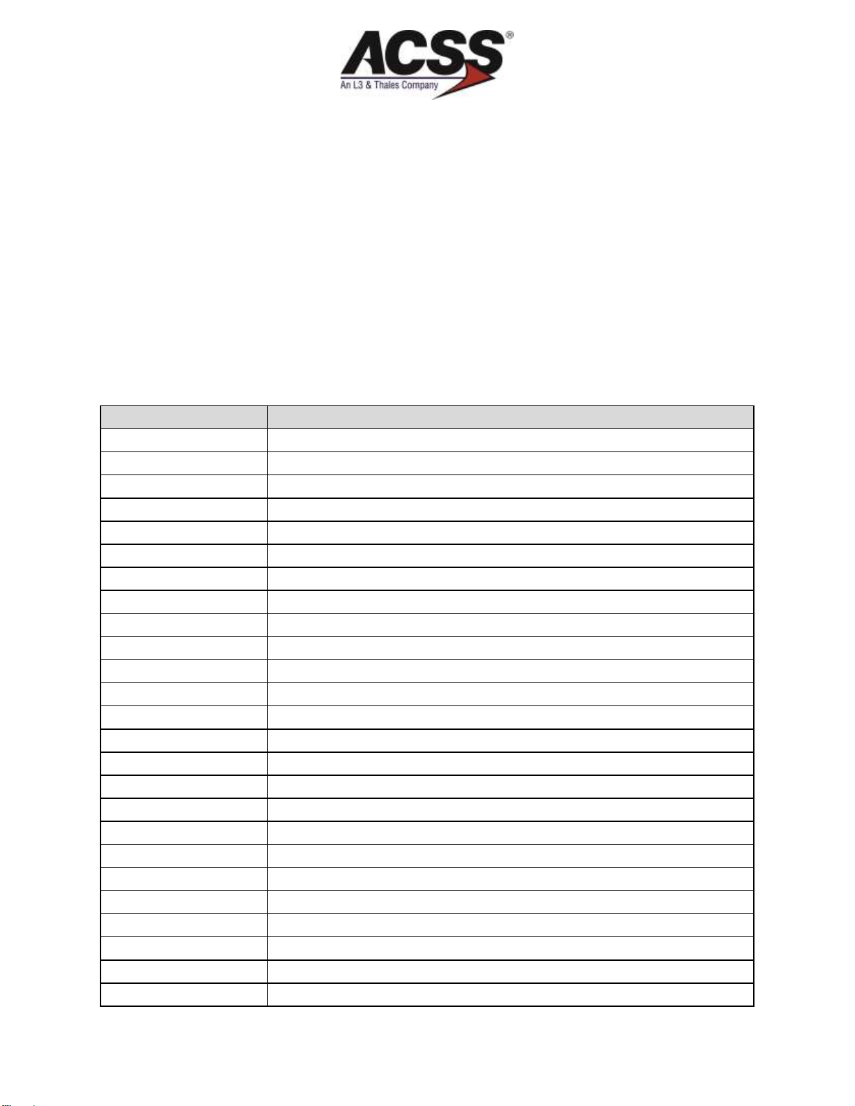
Table 2 –Acronyms and Abbreviations
(Continued)
Acronym/ Abbreviation
Description
AC
Advisory Circular (FAA)
ACSS
Aviation Communication & Surveillance Systems
ADS-B
Automatic Dependent Surveillance –Broadcast
AML
Approved Model List
AMM
Aircraft Maintenance Manual
ARINC
Aeronautical Radio Incorporated
ATE
Automated Test Equipment
CD
Compact Disc
CFR
Code of Federal Regulations
CSV
Comma Separated Variables
DC
Direct Current
E/W
East/West
EEPROM
Electronically Erasable Programmable Read-Only Memory
EPROM
Erasable Programmable Read-Only Memory
EWIS
Electrical Wiring Interconnection System
FIS-B
Flight Information Services - Broadcast
FPGA
Field Programmable Gate Array
GICB
Ground Initiated Comm B
GND
Ground
GNSS
Global Navigation Satellite System
GPS
Global Positioning System
ICA
Instructions for Continued Airworthiness
IPC
Illustrated Parts Catalog
LEP
List of Effective Pages
LRU
Line Replaceable Unit

NXG-900 AML STC SYSTEM MAINTENANCE MANUAL
Pub. No. 8009949-610
1-3
Revision A
06 DEC 2018
Use or disclosure of information on this page is subject to the restrictions in the proprietary and export notices of this document.
Table 2 –Acronyms and Abbreviations
(Continued)
Acronym/ Abbreviation
Description
MAINT
Maintenance
MAT
Maintenance Application Tool
MPC
Maintenance PC
MSL
(altitude above) Mean Sea Level
mΩ
Milliohms
N/A
Not Applicable
N/S
North/South
No.
Number
OP
Operational
PC
Personal Computer
PLL
Phase Locked Loop
RAIM
Receiver Autonomous Integrity Monitoring
RTN
Return
SBAS
Satellite Based Augmentation Systems
TNC
Threaded Neill–Concelman
UART
Universal Asynchronous Receiver/Transmitter
UAT
Universal Access Transceiver
USB
Universal Serial Bus
UTC
Universal Time Coordinated
VDC
Volts DC
WAAS
Wide Area Augmentation System
Ω
Ohm’s

NXG-900 AML STC SYSTEM MAINTENANCE MANUAL
1-4
Pub. No. 8009949-610
06 DEC 2018
Revision A
Use or disclosure of information on this page is subject to the restrictions in the proprietary and export notices of this document.
Blank Page

NXG-900 AML STC SYSTEM MAINTENANCE MANUAL
Pub. No. 8009949-610
2-1
Revision A
06 DEC 2018
Use or disclosure of information on this page is subject to the restrictions in the proprietary and export notices of this document.
2 SYSTEM OVERVIEW
The NXG-900 contains an integrated WAAS capable GPS receiver. The GPS receiver provides ownship
aircraft position, velocity, and track information to the XS-950 transponder for the ADS-B Out position
messages. This ADS-B information is automatically transmitted to other aircraft and ground stations
providing immediate and accurate surveillance of ownship.
2.1 NXG-900
The NXG-900 is mounted remotely in the aircraft and electrically interfaces to the aircraft systems via the
J2/P2 and GPS-RF Connections. The J2/P2 connection is a 62-pin high density sub D connection that
receives +28 VDC power and Ground, discrete “Air/Ground” status from the aircraft, and ARINC-429 GPS
Position data to the XS-950 Transponder.
The GPS RF connector is used to connect the NXG-900 receiver to the GPS antenna through a low loss
Coaxial cable.
A Mini-B USB port is also available to establish communication between the unit and a MPC (Maintenance
PC) for maintenance and troubleshooting activities.
Figure 1 –NXG-900 Connector Reference
NXG-900 AML STC SYSTEM MAINTENANCE MANUAL
2-2
Pub. No. 8009949-610
06 DEC 2018
Revision A
Use or disclosure of information on this page is subject to the restrictions in the proprietary and export notices of this document.
Figure 2 –NXG-900 Interface Summary
2.2 Power Requirements
The NXG-900 operates at 28 VDC. Electrical load information is provided below. Appendix A contains
specific details to the load changes relating to the installation of the NXG-900.
Table 3 –NXG-900 Power Requirements
Characteristic
Current Draw
Power Consumption
Nominal
0.32 Amps @ 28.0 VDC
8.9 Watts @ 28.0 VDC
Maximum
0.41 Amps @ 28.0 VDC
11.5 Watts @ 28.0 VDC
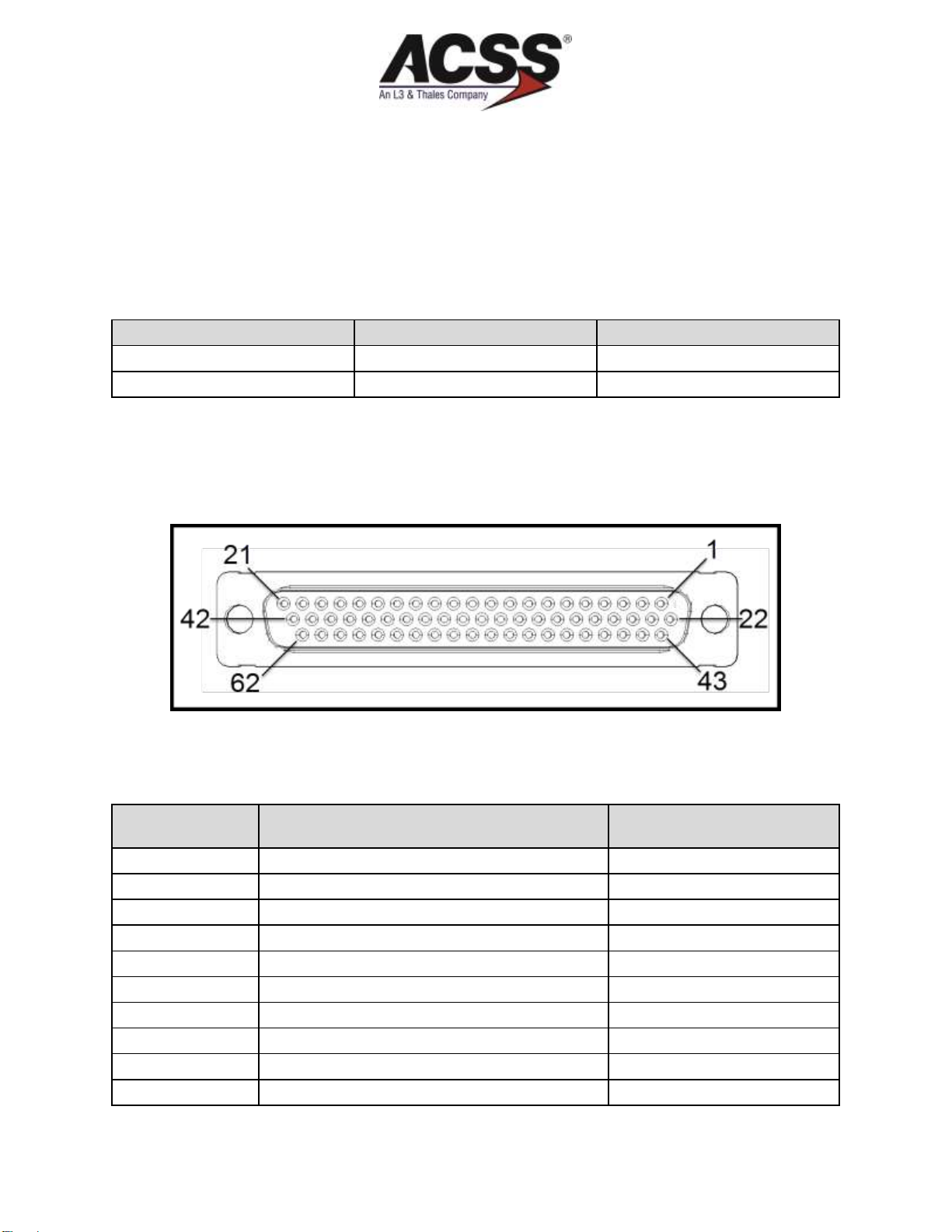
2.3 Connector Information
This purpose of this section is to describe the NXG-900 J2/P2 interfacing connection in more detail.
Figure 3 –Interfacing Connector P2 (Mating Side)
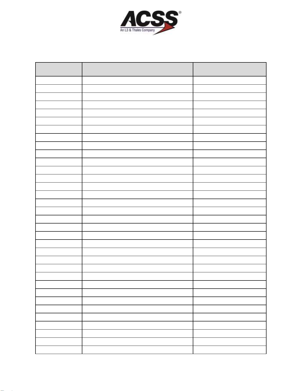
Table 4 –Interfacing Connector P2 Pin Layout
(Continued)
Input (I) or
Output (O)
Description
Connector-Pin
Spare
P2-1
Spare
P2-2
Spare
P2-3
Spare
P2-4
Spare
P2-5
(O)
A429 OUT A (+) A743A GPS DATA
P2-6
Spare
P2-7
Spare
P2-8
Spare
P2-9
Spare
P2-10
NXG-900 AML STC SYSTEM MAINTENANCE MANUAL
Pub. No. 8009949-610
2-3
Revision A
06 DEC 2018
Use or disclosure of information on this page is subject to the restrictions in the proprietary and export notices of this document.
Table 4 –Interfacing Connector P2 Pin Layout
(Continued)
Input (I) or
Output (O)
Description
Connector-Pin
Spare
P2-11
Spare
P2-12
Spare
P2-13
Spare
P2-14
Spare
P2-15
RESERVED
P2-16
Spare
P2-17
Spare
P2-18
Spare
P2-19
Spare
P2-20
(I)
+28VDC POWER IN 1
P2-21
Spare
P2-22
Spare
P2-23
Spare
P2-24
Spare
P2-25
(O)
A429 OUT B (-) A743A GPS DATA
P2-26
Spare
P2-27
RESERVED
P2-28
Spare
P2-29
RESERVED
P2-30
Spare
P2-31
Spare
P2-32
Spare
P2-33
Spare
P2-34
(I)
DC Ground
P2-35
Spare
P2-36
Spare
P2-37
Spare
P2-38
Spare
P2-39
Spare
P2-40
(I)
28V POWER RETURN 1 (GND)
P2-41
(I)
+28VDC POWER IN 2
P2-42
Spare
P2-43
Spare
P2-44

NXG-900 AML STC SYSTEM MAINTENANCE MANUAL
2-4
Pub. No. 8009949-610
06 DEC 2018
Revision A
Use or disclosure of information on this page is subject to the restrictions in the proprietary and export notices of this document.
Table 4 –Interfacing Connector P2 Pin Layout
(Continued)
Input (I) or
Output (O)
Description
Connector-Pin
Spare
P2-45
Spare
P2-46
Spare
P2-47
Spare
P2-48
RESERVED
P2-49
Spare
P2-50
Spare
P2-51
Spare
P2-52
(I)
WEIGHT ON WHEELS / AIR SPEED MONITOR
/ AIR/GROUND INDICATION
P2-53
Spare
P2-54
Spare
P2-55
Spare
P2-56
Spare
P2-57
Spare
P2-58
Spare
P2-59
Spare
P2-60
Spare
P2-61
(I)
28V POWER RETURN 2 (GND)
P2-62
Table 5 –Loading/Gradient Specifications
(Continued)
Connector-Pin
Functional Description
P2-21
P2-42
NXG-900 +28V POWER:
These pins along with two return lines (P2-41, 62) provide the +28 volt power
requirements for the NXG-900.
P2-41
P2-62
NXG-900 28V POWER RETURN:
These pins along with two power lines (P2-21, 42) provide the +28 volt power
requirements for the NXG-900.
P2-35
DC GROUND:
To be connected to aircraft dc ground.

NXG-900 AML STC SYSTEM MAINTENANCE MANUAL
Pub. No. 8009949-610
2-5
Revision A
06 DEC 2018
Use or disclosure of information on this page is subject to the restrictions in the proprietary and export notices of this document.
Table 5 –Loading/Gradient Specifications
(Continued)
Connector-Pin
Functional Description
P2-6
P2-26
ARINC 429 GPS Output: (P2-6 A[+], P2-26 B[-])
This ARINC 429 bus is used to output (high speed) the following labels to the
Transponder:
Label Description
076 GNSS Altitude (MSL)
103 GNSS True Track Angle
110 GNSS Latitude, Coarse
111 GNSS Longitude, Coarse
112 GNSS Ground Speed
120 GNSS Latitude, Fine
121 GNSS Longitude, Fine
130 GNSS Horizontal Integrity Limit
133 GNSS Vertical Integrity Limit
136 GNSS Vertical Figure of Merit
140 GNSS UTC, Fine (binary, “0.200 sec”)
150 GNSS UTC (binary, e.g., “12 h 23 m 12 s”)
165 GNSS Vertical Velocity
166 GNSS N/S Velocity
174 GNSS E/W Velocity
247 GNSS Horizontal Figure of Merit
370 GNSS Geodetic Height (above WGS-84 ellipsoid)
P2-53
Air/Ground Discrete Input:
Convention:
Open = In-air
Ground = On Ground.
This pin provides a method for the NXG-900 receiver to automatically determine the
Air/Ground status of the aircraft. The status is used in determination of fault logging
and in establishing when maintenance commands can be accepted by the system.
This pin is typically connected to the Air/Ground Relay (Squat Switch). Other
options include connecting to the Gear Switch, Airspeed Monitor, or Collective
Switch.
NOTE: Maintenance connection can only be established while the aircraft is in the
“on-ground” mode (P2-53 is grounded), or within two minutes of being
powered up.

NXG-900 AML STC SYSTEM MAINTENANCE MANUAL
2-6
Pub. No. 8009949-610
06 DEC 2018
Revision A
Use or disclosure of information on this page is subject to the restrictions in the proprietary and export notices of this document.
Blank Page

NXG-900 AML STC SYSTEM MAINTENANCE MANUAL
Pub. No. 8009949-610
3-1
Revision A
06 DEC 2018
Use or disclosure of information on this page is subject to the restrictions in the proprietary and export notices of this document.
3 CONTROL AND OPERATION
3.1 Controls
The NXG-900 has no external controls during normal operation other than using the installed circuit breaker
as a means to perform the NXG-900 Functional Test. Refer to Section 7 for other maintenance interfacing
options.
3.2 ADS-B Operation
During normal operation the NXG-900 provides the XS-950 Transponder system with GPS Position and
Tracking information over the ARINC 429 connection as defined in Section 2.3 (Table 5).
3.3 ADS-B Failures
A failure of the NXG-900 will cause an ADS-B Fail annunciation from the XS-950 Transponder system.
Refer to the XS-950 System Configuration Log retained in the aircraft permanent records for a list of the
interfaced equipment and system configuration data for how ADS-B Failures are annunciated.
If an ADS-B failure is annunciated, refer to Section 5 for troubleshooting information.

NXG-900 AML STC SYSTEM MAINTENANCE MANUAL
3-2
Pub. No. 8009949-610
06 DEC 2018
Revision A
Use or disclosure of information on this page is subject to the restrictions in the proprietary and export notices of this document.
Blank Page
Table of contents
Popular Marine Radio manuals by other brands

Raymarine
Raymarine Ray49E Owner's handbook

West Marine
West Marine VHF595 owner's manual

Garmin
Garmin VHF 720 Specifications

MicroAir Avionics
MicroAir Avionics T2000UAV-L Installation and user manual

Cobra Marine
Cobra Marine Marine MR HH125 Manual del propietario

Cobra Marine
Cobra Marine MR HH600 FLT GPS BT owner's manual


