Igloo JOLA 4 Series User manual

1
pl
Instrukcja obsługi JOLA 4www.igloo.pl
Spis treści Spis rysunków
Spis tabel
Rys.1 Budowa urządzenia 2
Rys.2 Zestaw kołowy, jezdny 3
Rys.3 Mocowanie uchwytu drzwi 4
Rys.4 Mocowanie półek szklanych 4
Rys.5 Panel sterowania 4
Rys.6 Otwory wentylacyjne urządzenia 5
Rys.7 Czyszczenie skraplacza 6
Rys.8 Wymiana świetlówki 7
Rys.9 Tabliczka znamionowa 8
Rys.10 Panel termostatu „Igloo” 9
Rys.11 Panel termostatu „Carel” 10
1. ROZŁADUNEK 1
2. CHARAKTERYSTYKA WYROBU 1
2.1. Przeznaczenie 1
2.2. Opis urządzenia 1
2.3. Dane techniczne 2
3. PRZYGOTOWANIE URZĄDZENIA DO EKSPLOATACJI 3
3.1. Wymagania dotyczące miejsca instalacji 3
3.2. Podłączenie i uruchomienie 3
4. EKSPLOATACJA 4
4.1. Regulacja temperatury 5
5. KONSERWACJA 6
5.1. Czyszczenie i konserwacja 6
6. SERWIS 7
6.1. Identyfikacja i naprawa usterek 7
6.2. Serwis 8
7. OBSŁUGA TERMOSTATU 9
7.1. Termostat „IGLOO” 9
7.2. Termostat „CAREL” 10 Tabela 1 Dane techniczne 2
1. ROZŁADUNEK
Urządzenie powinno byćtransportowane w pozycji pionowej, odpowiednio zabezpieczone i spakowane. Producent wy-
syła urządzenie zabezpieczone tekturowymi kątownikami oraz folią.
2. CHARAKTERYSTYKA WYROBU
2.1. Przeznaczenie
Szafa „Jola 4” jest urządzeniem chłodniczym, przeznaczonym do ekspozycji i krótkoterminowego przechowywania wy-
robów cukierniczych: tortów, ciast, ciasteczek, deserów itp. w temperaturach +4ºC/+8ºC przy temperaturze otoczenia
+15ºC/+25ºC i wilgotności wzgl. powietrza do 60%.
2.2. Opis urządzenia
„Jola 4” jest szafąchłodnicząz agregatem wewnętrznym, z wymuszonym obiegiem powietrza. Szafa wyposażona jest w
odszranianie automatyczne, automatyczne odparowanie kondensatu i elektroniczny termostat opcjonalnie współpracują-
cy z modułem do rejestracji temperatury pozwalającym na rejestracjęi sygnalizacjęza wysokiej i za niskiej temperatury
w urządzeniu. Część ekspozycyjnąszafy stanowiąpółki szklane, obrotowe lub stałe z możliwościąregulacji wysokości
położenia. W zależności od przeznaczenia szafa wykonywana jest w wersji stacjonarnej lub jezdnej. Urządzenia „IGLOO”
wykonywane sąw/g nowoczesnych technologii i posiadająwymagane prawem certyfikaty.
Tym znakiem oznaczone sąinformacje o szczególnym znaczeniu dla bezpieczeństwa użytkownika
oraz do prawidłowej eksploatacji urządzenia
Instrukcja obsługi JOLA 4
pl

2
pl
Instrukcja obsługi JOLA 4 www.igloo.pl
1 – Półka szklana (obrotowa lub stała)
2 – Uchwyt drzwi
3 – Obudowa (metalowa/drewniana/drewniana Retro)
4 - Wiatrownica przednia (NIE BLOKOWAĆOTWORÓW!!!)
5 – Zawias drzwi
6 – Panel sterowania (termostat/wyłączniki)
7 - Tabliczka znamionowa
8 – Wiatrownica boczna, lewa (po ściągnięciu dostęp do lamel skraplacza) – NIE BLOKOWAĆOTWORÓW!!!
9 - Nóżki służące do wypoziomowania urządzenia
2.3. Dane techniczne
Tabela 1 Dane techniczne
Nazwa urządzenia
Napięcie
znamion.
[V/Hz]
Prąd zna-
mion.
[A]
Moc znamion.
oświetl.
[W]
Zużycie
energii elektr.
[kWh/24h]
Obciąż. półki
[kg]
Waga urz.
[kg]
JOLA 4/MAL 230/50 2,6 72 5,8 15 155
JOLA 4/DRE* 230/50 2,6 72 5,8 15 185
JOLA 4 OBR/MAL 230/50 2,6 72 5,8 10 160
JOLA 4 OBR/DRE* 230/50 2,6 72 5,8 10 190
Rys.1 Budowa urządzenia
NS-069XXX
MASAxxx
NAPIECIEZNAM.xxx
MOCZN.OŒW.xxx
MOCGRZA£EK.xxx
NAPIECIEZNAM.xxx
KLASAURZADZ.xxx
TypNAZWAURZ¥DZENIA
PR¥DZNAM.xxx
1
2
3
5
6
7
48
9
* Dotyczy równieżwersji „RETRO”

3
pl
Instrukcja obsługi JOLA 4www.igloo.pl
3. PRZYGOTOWANIE URZĄDZENIA DO EKSPLOATACJI
3.1. Wymagania dotyczące miejsca instalacji
• Sprawdź, czy przekrój przewodów zasilających jest odpowiedni dla poboru prądu instalowanego urządzenia
• Zabrania siępodłączania urządzenia przez przewody przedłużające lub rozdzielacze
• Urządzenie należy podłączyćdo oddzielnego, prawidłowo wykonanego obwodu elektrycznego z gniazdem
wtykowym z kołkiem ochronnym (w/g PBUE)
Uruchomienie urządzenia, może nastąpićtylko po potwierdzeniu skuteczności ochrony przeciwporaże-
niowej wynikami z pomiarów, przeprowadzonymi zgodnie z obowiązującymi przepisami!
3.2. Podłączenie i uruchomienie
• Rozpakowaćurządzenie
• Urządzenie ustawićna równym i dostatecznie twardym podłożu, a następnie wypoziomowaćje za pomocąnóżek
Rys.1/9 (str.2). W przypadku szaf jezdnych należy zastosowaćblokadękółw celu uniemożliwienia przesuwania się
ich podczas eksploatacji Rys.2 (str.3).
• Jeżeli urządzenie trafido użytkownika częściowo zdemontowane dla zabezpieczenia w czasie transportu należy
wykonaćnastępujące operacje:
I. Przykręcićuchwyt drzwi Rys.3 (str.4)
II. Zamontowaćuchwyty półek w perforowanych listwach stelaża Rys.4/2 (str.4)
Ze względu na wersjęszafy stelażmoże byćobrotowy lub na stałe przymocowany do korpusu.
III. Na uchwytach półek przykleićbumbony (silikonowe elementy zabezpieczające półkęszklanąprzed
przesuwaniem się) Rys.4/4 (str.4)
IV. Na zamocowanych uchwytach umieścićpółki szklane Rys.4/1 (str.4)
„Jola 4” posiada 5 regulowanych półek szklanych okrągłych lub prostokątnych (w zależności od opcji szafy). Szafa
z obrotowym stelażem („OBR”) posiada cztery górne półki szklane, a piąta półka dolna wykonana jest z lustra.
A – pozycja jezdna
B – pozycja blokady
Rys.2 Zestaw kołowy, jezdny
• Umieścićwtyczkęprzewodu przyłączeniowego bezpośrednio w gnieździe wtykowym (zabrania siępodłączania urzą-
dzenia przez przewody przedłużające lub rozdzielacze!)
• Załączyćprzycisk wyłącznika głównego Rys.5/2 (str.4), co spowoduje załączenie regulatora temperatury, a następnie
agregatu urządzenia
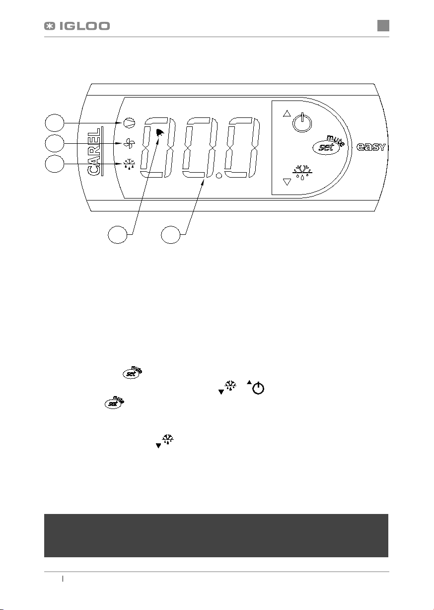
• Na panelu termostatu Rys.5/1 (str.4) ustawićtemperaturę(szczegóły obsługi na str.9 lub 10)
• Załączyćprzycisk oświetlenia wewnątrz szafy Rys.5/3 (str.4)
• Załączyćprzycisk obrotu stelaża Rys.5/4 (str.4) (dotyczy tylko szaf „OBR”)
B
A
• Pierwsze mycie urządzenia powinno byćwykonane po rozpakowaniu urządzenia i przed jego uruchomieniem. Urzą-
dzenie należy umyćwodąo temperaturze nieprzekraczającej 40ºC z dodatkiem neutralnych środków czyszczących.
Do mycia i czyszczenia urządzenia zabrania sięstosowania środków zawierających chlor i sód różnych odmian,
które niszcząwarstwęochronnąi elementy składowe urządzenia
!
Ewentualne pozostałości klejów czy silikonu
na elementach metalowych urządzenia usuwaćwyłącznie benzynąekstrakcyjną(nie dotyczy elementów z plastiku i
tworzyw sztucznych!). Nie wolno używaćinnych rozpuszczalników organicznych.
Podczas mycia urządzenia zabrania sięużywaćstrumienia wody. Urządzenie należy myć
przy użyciu wilgotnej ściereczki
Po zakończeniu instalacji urządzenia w miejscu docelowym należy pozostawićje w spoczynku, przez co
najmniej 2 godziny przed włączeniem (dotyczy urządzeńz agregatem wewnętrznym), aby poziom oleju
ustaliłsię, co zapobiegnie problemom z rozruchem agregatu chłodniczego!
OSTRZEŻENIE: Chronićprzed uszkodzeniem obwód chłodniczy!

4
pl
Instrukcja obsługi JOLA 4 www.igloo.pl
1
2
3
4
1 – Półka szklana
2 - Uchwyt mocowania półki
3 – Perforowana listwa stelaża
4 – Bumbon – silikonowy element
zabezpieczający półkęszklanąprzed
przesuwaniem się(bezwzględnie
należy przykleićgo do uchwytu
mocowania półki!!!)
1 – Panel termostatu (regulatora temperatury)
(szczegóły obsługi w Rozdziale 7 str.9 lub 10)
2 - Wyłącznik główny (załącza/wyłącza agregat urządzenia)
3 – Wyłącznik oświetlenia wewnętrznego
4 – Wyłącznik obrotu stelaża
Rys.3 Mocowanie uchwytu drzwi
Rys.4 Mocowanie półek szklanych
Rys.5 Panel sterowania
1
2 3 4
Stelażobrotowy uruchamiany jest za pomocąprzycisku wyłącznika
umieszczonego na panelu sterowania szafy. Każde otwarcie drzwi sza-
fy spowoduje, że obrót stelaża zostanie wstrzymany na czas otwar-
cia drzwi. Zamknięcie drzwi spowoduje ponowne włączenie ruchu
obrotowego stelaża.
4. EKSPLOATACJA
Temperatura chłodzonej przestrzeni i cykl pracy agregatu mogąulegaćwahaniom. Zależą one od wielu czynni-
ków m. in. od ilości i temperatury włożonych produktów oraz od temperatury otoczenia. Należy unikaćzbędnego
otwierania drzwi.Urządzenie należy ustawićw miejscu suchym, nienasłonecznionym, dobrze wentylowanym, za-
pewniającym dobrąwymianępowietrza (dystans pomiędzy ścianą, a urządzeniem min. 100 mm), z dala od źródeł
ciepła i urządzeńwymuszających przepływ powietrza (wentylatory sufitowe i przenośne, grzejniki nadmuchowe).
Urządzenie funkcjonuje poprawnie w środowisku, w którym temperatura zawiera sięw odpowiedniej klasie klima-
tycznej podanej na tabliczce znamionowej. Działanie urządzenia może ulec pogorszeniu, gdy przez dłuższy czas
funkcjonowaćbędzie w temperaturze wyższej lub niższej w stosunku do podanego przedziału.
NIE BLOKOWAĆOTWORÓW WENTYLACYJNYCH!!! Minimalna odległość pomiędzy otworami wen-
tylacyjnymi urządzenia, a innymi elementami wyposażenia (meblami) lub ścianami powinien wynosićok.
10 cm.

5
pl
Instrukcja obsługi JOLA 4www.igloo.pl
Uwagi i wskazówki
• Pierwsze zapełnienie przestrzeni chłodniczej dokonywaćpo uprzednim jej wychłodzeniu do temperatury pra-
cy. Zasada ta powinna byćtakże przestrzegana po dłuższej przerwie w eksploatacji
• Nie wstawiaćciepłych produktów do urządzeńchłodniczych
• Należy zapewnićrównomierne obciążenie półek i nie przekraczaćich maksymalnego obciążenia
• Nie blokowaćżadnych otworów wentylacyjnych, co mogłoby utrudnićcyrkulacjęschłodzonego powietrza.
Należy zapewnićrównieżprawidłowy obieg powietrza wokółurządzenia (w żadnym wypadku nie wolno za-
krywaćotworów wentylacyjnych agregatu!!!)
• Utrzymywaćskraplacz w czystości. Zanieczyszczenia mogąspowodowaćprzegrzanie sprężarki i w efekcie
doprowadzićdo awarii urządzenia, co nie jest objęte gwarancją!
• Wewnątrz komory do przechowywania produktów żywnościowych nie używaćprzyrządów elektrycznych
4.1. Regulacja temperatury
Obsługa termostatów (regulatorów temperatury) „Igloo” i „Carel” znajduje sięw rozdziale 7 (str. 9 i 10)
Podstawowym zadaniem termostatu jest sterowanie agregatem chłodniczym tak, aby uzyskaćzadanątemperaturęwe-
wnątrz urządzenia i utrzymywaćjąw określonych przedziałach. Wszystkie nastawy regulatora temperatury konieczne do
normalnego funkcjonowania urządzenia sąwprowadzone przez producenta. Użytkownik przed pierwszym uruchomie-
niem urządzenia powinien sprawdzići ewentualnie ustawićna panelu żądanątemperaturęwewnątrz urządzenia.
Cyfrowy wyświetlacz – wyświetla bieżącątemperaturęwewnątrz urządzenia
Niedozwolone jest ingerowanie w parametry systemowe termostatu, gdyżmoże to spowodowaćbardzo
poważne konsekwencje włącznie ze zniszczeniem urządzenia chłodniczego!
~10 cm
~10 cm
Rys.6 Otwory wentylacyjne urządzenia

6
pl
Instrukcja obsługi JOLA 4 www.igloo.pl
5. KONSERWACJA
5.1. Czyszczenie i konserwacja
Wszelkie czynności konserwacyjne należy prowadzićpo odłączeniu urządzenia od napięcia!
Chronićprzed uszkodzeniem lub zalaniem wodąinstalacjęelektryczną
Do czyszczenia urządzenia nie należy używaćstrumienia wody, a jedynie wilgotnej ściereczki
Nie należy stosowaćżadnych ostrych przedmiotów celem usuwania zabrudzeń!
Urządzenia wyposażone w kółka jezdne nie mogąbyćeksploatowane na nierównych powierzchniach!
Raz na miesiączaleca sięprzerwęw eksploatacji urządzenia celem oczyszczenia jego wnętrza, naturalnego odszronie-
nia parownika, oczyszczenia skraplacza i sprawdzeniu stanu uszczelek drzwi.
W celu przyspieszenia procesu odszraniania nie posługiwaćsięśrodkami mechanicznymi!
Skraplacz urządzenia należy utrzymywaćw czystości. Zanie-
czyszczenia utrudniająwymianęciepła, powodując m. in. wzrost
zużycia energii elektrycznej i mogąspowodowaćuszkodzenie
sprężarki agregatu.
Aby wyczyścićskraplacz należy ściągnąć wiatrownicęlewą, bocz-
nąunosząc jądelikatnie do góry. Lamele skraplacza czyścićza
pomocąmiękkiej szczotki lub pędzla. Przy mocnym zabrudzeniu
(zapchaniu lamel) skraplacza wskazane jest użycie odkurzacza
lub sprężonego azotu w celu odessania/ wydmuchania zabru-
dzeńznajdujących sięmiedzy lamelami.
Za uszkodzenia agregatu skraplającego powstałe w wyniku nieprzestrzegania czystości skraplacza pro-
ducent nie ponosi odpowiedzialności!
Uszczelkędrzwi należy czyścićwyłącznie czystąwodąbez dodatku środków myjących i pamiętaćo jej
dokładnym wysuszeniu. Uszczelka nie może miećkontaktu z substancjami tłustymi ani olejami!
Podczas czynności konserwujących należy sprawdzićczy drzwi zamykająsięwłaściwie.
Próba: umieścićkartkępapieru pomiędzy uszczelką, a obudowąi zamknąć drzwi. Papier powinien
stawiaćwyczuwalny opór przy próbie wyciągania
Rys.7 Czyszczenie skraplacza
Elementy urządzenia mogąkorodowaćprzy niewłaściwym użytkowaniu i konserwacji.
Należy przestrzegaćzasad:
• Nie dopuszczaćdo kontaktu powierzchni urządzenia z środkami zawierającymi chlor i/lub sodę
w różnych odmianach, które niszcząich warstwęochronnąi elementy składowe urządzenia
(dotyczy równieżróżnych gatunków stali nierdzewnej)

7
pl
Instrukcja obsługi JOLA 4www.igloo.pl
1 – Zapłonnik świetlówki
2 – Profil bazowy
3 – Oprawy świetlówki i zapłonnika
4 – Świetlówka
5 – Przeźroczysta osłona świetlówki
Rys.8 Wymiana świetlówki
2
54
1
3
Podczas czynności konserwujących należy uważać, aby nie uszkodzićtabliczki znamionowej urzą-
dzenia Rys.9 (str.8), która zawiera istotne informacje dla serwisantów oraz firm zajmujących sięusu-
waniem odpadów.
6. SERWIS
6.1. Identyfikacja i naprawa usterek
W przypadku wystąpienia jakichkolwiek trudności podczas uruchamiania urządzenia lub podczas jego eksploatacji należy
powrócićdo tych rozdziałów instrukcji obsługi, które wyjaśniająwykonywanąoperację. Ma to na celu upewnienie się, czy
urządzenie jest prawidłowo obsługiwane. Jeżeli trudności występująnadal, poniższe wskazówki pomogąw ich usunięciu.
Urządzenie nie pracuje...- Upewnićsię, czy:
• Urządzenie jest podłączone do sieci prądu elektrycznego
• Napięcie i częstotliwość w sieci sąodpowiednie z tymi, jakie zaleca producent (patrz tabliczka znamionowa)
• Włączony jest wyłącznik główny
• Termostat jest załączony (Dotyczy term. Igloo – Jeśli na wyświetlaczu wyświetlająsięjedynie dwie kropki – włącz termostat)
Urządzenie pracuje, oświetlenie nie świeci...- Upewnićsię, czy:
• Wyłącznik oświetlenia jest w pozycji załączonej
• Świetlówka lub zapłonnik w urządzeniu nie uległy spaleniu
Urządzenie nie osiąga odpowiedniej temperatury, oświetlenie świeci...- Upewnićsię, czy:
• Wyłącznik główny jest w pozycji załączonej
• Nastawa temperatury na termostacie jest odpowiednio ustawiona
• Termostat działa poprawnie
• Skraplacz nie jest zanieczyszczony, w razie potrzeby wyczyścić
• Temperatura otoczenia nie jest wyższa niż25ºC
• Minęło wystarczająco dużo czasu dla schłodzenia produktów
• Drzwiczki urządzenia zamykająsięwłaściwie i czy uszczelka przylega do korpusu urządzenia
• Otwory wentylacyjne urządzenia nie sązablokowane
(Dotyczy term. „IGLOO”) Termostat wyświetla C0 lub C1 lub C2 zamiast temperatury:
Sytuacja taka ma miejsce, jeżeli zostałuszkodzony jeden z czujników regulatora wówczas mogąpojawićsię
następujące komunikaty:
• C0 –uszkodzenie czujnika temperatury wewnątrz komory –wezwaćautoryzowany serwis
• C1 –uszkodzenie czujnika parownika - wezwaćautoryzowany serwis
• C2 –uszkodzenie czujnika alarmu skraplacza (lub uszkodzenie drugiego czujnika parownika) – wezwaćautoryzowany
serwis

8
pl
Instrukcja obsługi JOLA 4 www.igloo.pl
Odgłosy wydawane przez urządzenia pracujące sązjawiskiem normalnym. W urządzeniach znajdująsię
wentylatory, silniki i sprężarki, które włączająsięi wyłączająautomatycznie. Każda sprężarka wytwarza
pewien hałas podczas pracy. Dźwięki te wytwarzane sąprzez silnik agregatu oraz przez czynnik
chłodniczy przepływający w obwodzie. Zjawisko to jest cechątechnicznąurządzeńchłodniczych i
nie oznacza ich wadliwej pracy.
Osadzanie siępary wodnej na szybach urządzenia przy dużej wilgotności względnej powietrza
powyżej 60% jest zjawiskiem naturalnym i nie wymaga wzywania serwisu!
(Dotyczy term. „CAREL”) Termostat wyświetla E0 lub E1 lub L0 lub HI lub EE lub Ed lub DF zamiast temperatury:
• E0 -uszkodzenie czujnika temperatury wewnątrz komory- wezwaćautoryzowany serwis
• E1 -uszkodzenie czujnika parownika - wezwaćautoryzowany serwis
• L0 –alarm niskiej temperatury (niższej niżzadany zakres wewnątrz urządzenia) - wezwaćautoryzowany serwis
• HI - alarm wysokiej temperatury - wezwaćautoryzowany serwis
• EE -błąd wewnętrzny regulatora - wezwaćautoryzowany serwis
• Ed – przekroczenie max. czasu odszraniania
• DF – odszranianie w toku (to nie jest sygnałalarmowy)
(Dotyczy term. „IGLOO”) Urządzenie pracuje, włączona sygnalizacja dźwiękowa...- Upewnićsię, czy
• Skraplacz nie jest zanieczyszczony, w razie potrzeby wyczyścić
• Pracuje wentylator skraplacza
• Temperatura otoczenia nie przekracza 25ºC
Urządzenie pracuje zbyt głośno...- Upewnićsię, czy
• Urządzenie stoi stabilnie i czy jest prawidłowo wypoziomowane
• Przylegające do urządzenia meble nie drgająpodczas pracy sprężarki agregatu chłodniczego
Urządzenie pracuje, stelażnie obraca się...- Upewnićsię, czy:
• Wyłącznik obrotu stelaża jest w pozycji załączonej
• Drzwi szafy sązamknięte
6.2. Serwis
Jeśli po sprawdzeniu punktów opisanych w rozdziale 6.1 „Identyfikacja i naprawa usterek” urządzenie nadal nie działa
prawidłowo, należy skontaktowaćsięz Serwisem Technicznym firmy Igloo, podając dane z tabliczki znamionowej Rys.9
(str.8):
• Numer seryjny (NS)
• Datęprodukcji
• Typ (nazwa urządzenia)
oraz
• Datęzakupu urządzenia
• Opis problemu
• Dokładny adres i numer telefonu wraz
z numerem kierunkowym do Państwa
Powyższy rysunek przedstawia poglądowątabliczkę
znamionową, a dane w niej zawarte sądanymi przykła-
dowymi nieodnoszącymi siędo „Joli 4”!
Rys.9 Tabliczka znamionowa

9
pl
Instrukcja obsługi JOLA 4www.igloo.pl
Sprawdzanie nastawionej temperatury (wewnątrz urządzenia) – Naciskając przycisk „▲” lub „▼” jeden raz możemy
sprawdzićnastawionątemperaturę. Na wyświetlaczu pojawia sięnastawiona temperatura, przy której świeci sięczerwo-
na mrugająca kropka (dioda). Wyjście z podglądu następuje automatycznie po ok. 3 sekundach.
Obniżenie (lub podwyższenie) temperatury – naciskamy przycisk „▼” (lub „▲”) i na panelu pojawi sięustawiona tempe-
ratura. Naciskając przycisk „▼” obniżamy temperaturędo żądanej wartości. Wyjście z funkcji następuje automatycznie
po ok. 3 sek.
Ręczne odszranianie –przycisk nr 2 pozwala na włączenie cyklu odszraniania w dowolnym momencie pracy urządzenia
(niezależnie od funkcji automatycznego odszraniania); przycisk nie działa, gdy temperatura jest wyższa niżtemperatura
końca odszraniania
Zaleca się, aby użytkownik załączał/wyłączałagregat korzystając jedynie z wyłącznika głównego urzą-
dzenia, a nie z przycisku bezpośrednio na panelu termostatu. Załączenie wyłącznika głównego automa-
tycznie załącza termostat!
* Więcej na stronie www.igloo.pl
1 – Przycisk włącz/wyłącz chłodzenie
2 – Przycisk ręcznego odszraniania
3 – Kontrolka pracy agregatu i odszraniania
4 - Przycisk podglądu temp. na czujniku odszraniania
5 – Przycisk zmiany temp. do góry
6 – Przycisk zmiany temp. w dół
7. OBSŁUGA TERMOSTATU
7.1. Termostat „IGLOO”
Rys.10 Panel termostatu "Igloo"

10
pl
Instrukcja obsługi JOLA 4 www.igloo.pl
1
2
3
5
4
CO OZNACZAJĄDIODY NA WYŚWIETLACZU
Zapalona dioda 1 - Sprężarka: symbol jest widoczny, gdy sprężarka pracuje. Miga, gdy start sprężarki jest opóźniony
przez proceduręochronną. Miga w cyklu: dwa mignięcia – przerwa, gdy uruchomiony jest tryb pracy ciągłej.
Zapalona dioda 2 - Wentylator: symbol jest widoczny, gdy włączone sąwentylatory parownika. Miga, gdy start wentyla-
torów jest opóźniony poprzez zewnętrzne wyłączenie lub, podczas gdy inna procedura jest w toku.
Zapalona dioda 3 - Odszranianie: symbol jest widoczny, gdy włączona jest funkcja odszraniania. Miga, gdy start odszra-
niania jest opóźniony poprzez zewnętrzne wyłączenie lub podczas, gdy inna procedura jest w toku.
Zapalona dioda 4 - Alarm: symbol jest widoczny, gdy aktywny jest alarm
Zapalona dioda 5 – wyświetlana bieżąca temperatura wewnątrz urządzenia (po przecinku wyświetlane miejsca dzie-
siętne)
NASTAWA ŻĄDANEJ TEMPERATURY
- naciśnij przez 1 sekundę: wartość wodząca pojawi sięna ekranie;
- zwiększ lub zmniejsz wartość wodzącąużywając klawiszy i , ażosiągniesz pożądanąwartość;
- naciśnij ponownie w celu potwierdzenia nowej wartości punktu nastawy;
RĘCZNE WYMUSZENIE CYKLU ODSZRANIANIA
Odszranianie realizowane jest w sposób automatyczny. Można jednak w dowolnej chwili wymusićodszranianie poprzez
naciśnięcie i przytrzymanie przycisku przez minimum 5 sekund. Podczas ręcznego odszraniania miga dioda 1.
* Więcej na stronie www.alfaco.pl
7.2. Termostat „CAREL”
Rys.11 Panel termostatu "Carel"
UWAGA: W PRZYPADKU NIE ZASTOSOWANIA SIĘDO ZASAD ZAWARTYCH W NINIEJSZEJ INSTRUKCJI DO-
TYCZĄCYCH PODŁĄCZENIA I EKSPLOATACJI URZĄDZENIA, PRODUCENT ZASTRZEGA SOBIE PRAWO OD-
STĄPIENIA OD OBOWIĄZKÓW GWARANTA!!!
Informacje zawarte w tym dokumencie mogąbyćzmienione przez „IGLOO” bez powiadamiania użytkownika.
Kopiowanie niniejszej instrukcji bez zgody producenta jest zabronione.
Zdjęcia oraz rysunki mającharakter poglądowy i mogąsięróżnićod zakupionego urządzenia.

en
11
User manual JOLA 4www.igloo.pl
1. UNLOADING
The device should be transported in vertical position, and it should be properly secured and packed. The manufacturer
ships the device on a special wooden platform, secured with cardboard angle sections and foil.
2. PROPERTIES OF THE DEVICE
2.1. Purpose
“Jola 4” display case is a cooling device, used to display and short-term storing of confectionery products: cakes,
pastries, cookies, desserts, etc. in temperatures ranging between +4ºC and +8ºC with ambient temperature ran-
ging between +15ºC and +25ºC and relative air humidity of up to 60%.
2.2. Description of the device
“Jola 4” is a cooling display case with internal aggregate and forced air circulation. The case is also equipped with auto-
matic defrosting, automatic condensate evaporation and electronic thermostat optionally cooperating with temperature
recording module enabling to record and signal too low and too high temperature within the device. Glass shelves, rotating
or fixed, with height regulation, constitute the display part of the case.
Depending on the purpose of the case is available in stationary and mobile version. Our devices are made according to
modern technologies and have all certificates required by law.
This sign signifies information of particular meaning for user security and for proper device
exploitation.
User manual
Fig.1 Construction of the device 12
Fig.2 Mobile, wheel system 13
Fig.3 Fixing the door grip 14
Fig.4 Mounting glass shelves 14
Fig.5 Control panel 14
Fig.6 Ventilation holes of the device 15
Fig.7 Cleaning the condenser 16
Fig.8 Exchange of the fluorescent lamp 17
Fig.9 Data plate 18
Fig.10 „Igloo” thermostat control panel 19
Fig.11 „Carel” thermostat control panel 20
Contents List of Figures
List of tables
Table 1 Technical data 12
1. UNLOADING 11
2. PROPERTIES OF THE DEVICE 11
2.1. Purpose 11
2.2. Description of the device 11
2.3. Technical data 12
3. PREPARING THE DEVICE FOR EXPLOITATION 13
3.1. Requirements concerning the place of installation 13
3.2. Connection and actuation 13
4. EXPLOITATION 14
4.1. Temperature regulation 15
5. MAINTENANCE 16
5.1. Cleaning and maintenance 16
6. SERVICE 17
6.1. Fault identification and repair 17
6.2. Service 18
7. THERMOSTAT SERVICE 19
7.1. “IGLOO” thermostat 19
7.2. “CAREL” thermostat 20
en
JOLA 4

en
12 User manual JOLA 4 www.igloo.pl
1 – Glass shelf (rotating or fixed)
2 – Door grip
3 – Casing (metal/wooden/wooden Retro)
4 – Front wind frame (DO NOT BLOCK VENTILATION HOLES!!!)
5 – Door hinge
6 – Control panel (thermostat/ switches)
7 – Data plate
8 – Side, left wind frame (when removed allows access to condenser lamellas) – DO NOT BLOCK THE HOLES!!!
9 – Feet used for levelling the device
2.3. Technical data
Table 1 Technical data
Name of the device Rated voltage
[V/Hz]
Rated current
[A]
Rated lighting
power
[W]
Electric
energy
consumption
[kWh/24h]
Shelf load
[kg]
Weight of the
device
[kg]
JOLA 4/MAL 230/50 2,6 72 5,8 15 155
JOLA 4/DRE* 230/50 2,6 72 5,8 15 185
JOLA 4 OBR/MAL 230/50 2,6 72 5,8 10 160
JOLA 4 OBR/DRE* 230/50 2,6 72 5,8 10 190
Fig.1 Construction of the device
NS-069XXX
MASAxxx
NAPIECIEZNAM.xxx
MOCZN.OŒW.xxx
MOCGRZA£EK.xxx
NAPIECIEZNAM.xxx
KLASAURZADZ.xxx
TypNAZWAURZ¥DZENIA
PR¥DZNAM.xxx
1
2
3
5
6
7
48
9
* Also concerns the “RETRO” device

en
13
User manual JOLA 4www.igloo.pl
3. PREPARING THE DEVICE FOR EXPLOITATION
3.1. Requirements concerning the place of installation
• Verify whether the cross-section of feeding conduits is proper for the power consumption of the installed device
• It is forbidden to connect the device by means of extension cords or dividers
• The device should be connected to the separate, properly made electric circuit with plug-in socket with protecting
pin (according to PBUE /Regulations concerning Electric Equipment Construction/)
The device may be actuated solely after confirmation of the fire protection efficiency with results of measu-
res performed according to binding regulations!
3.2. Connection and actuation
• Unpack the device
• Place the display cabinet on an even basis, which is hard enough, and then level it with feet Fig.1/9 (p.12). In case of
moving devices it is necessary to use wheel blockade in order to immobilise them during exploitation Fig. 2 (p.13).
• If the user shall obtain a device partially disassembled to secure it during transportation, perform the following ope-
rations:
I. Screw the door grip Fig.3 (p.14)
II. Fix shelf grips in perforated frame strips Fig.4/2 (p.14) Depending on the version of the case the frame may be a
rotating frame or may be constantly fixed to the body of the device.
III. Stick bumpons (silicone elements protecting the glass shelf against shifting) on shelf grips Fig. 4/4 (p.14)
IV. Place glass shelves on fixed grips Fig.4/1 (p.14)
“Jola 4” is equipped with 5 regulated round or rectangular glass shelves (depending on the option of the case). The
case with rotating frame (“OBR”) is equipped with four upper glass shelves, and the fifth bottom shelf is in the form
of mirror.
A – mobile position
B – blocked position
Fig.2 Mobile, moving system
• Place the plug of the connecting cable directly in plug-in socket (it is forbidden to connect the device by means of
extension cords or dividers!)
• Turn the main switch on Fig. 5/2 (p.14), which will activate the thermostat, and then the aggregate of the device.
• Set the temperature on the thermostat panel Fig.5/1 (p.14) (service details on p.19 or 20)
• Turn the lighting switch inside the cabinet Fig.5/3 (p.14)
• Turn on the frame rotating switch Fig.5/4 (p.14) (concerns only “OBR” cases)
B
A
• The first cleaning of the device should be provide right after unpacking, and before turning it on. The unit should
be cleaned with water at a temperature not exceeding 40°C with a neutral detergent. For washing and cleaning
the equipment it is prohibited to use products containing chlorine and sodium varieties, which destroy the protecti-
ve layer and components of the device! Any residue of adhesives or silicone on metal elements should be remo-
ved only with extraction naphtha (not applicable to items made of plastic !). Do not use other organic solvents.
When cleaning the unit is prohibited to use water jet. The unit should be cleaned with a wet rag.
After installation of the device at the destination place it should be left to rest for at least 2 hours before
turning it on (for devices with built in compressor) to set the level of refrigerant in order to prevent problems
with starting up the aggregate.
WARNING: Keep out the cooling circuit from damage!

en
14 User manual JOLA 4 www.igloo.pl
1
2
3
4
1 – Glass shelf
2 – Shelf fixing grip
3 – Perforated frame strip
4 – Bumpon – silicone element protecting
the glass shelf against moving (it has
to be essentially glued to the shelf
fixing grip!!!)
1 – Thermostat panel (temperature regulator) (details of service in
Chapter No. 7 on p.19 or 20)
2 – Main switch (turns on/ off the aggregate of the device)
3 _ Switch of the internal illumination
4 – Switch of the frame rotation
Fig.3 Fixing the door grip
Fig.4 Mounting glass shelves
Fig.5 Control panel
1
2 3 4
The rotating frame is activated with the help of switch placed on case
control panel. Each opening of case doors stops the rotation of the
frame for the time when doors are open. Closing the door will once
again activate the movement of rotating frame.
4. EXPLOITATION
Temperature of cooled space and operating cycle of the aggregate may vary. They depend on numerous factors,
such as amount and temperature of products placed in the device and the ambient temperature. It is recommended
to avoid unnecessary opening of the doors.
The device should be placed in a dry place, not insolated and well ventilated, ensuring proper air circulation (min.
100 mm distance between the wall and the device), far from sources of heat and devices forcing the air circulation
(roof ad mobile ventilators, blowing heaters). The device operates properly in an environment, where temperature
falls within proper climate class stated on the data plate. The operation of the device may worsen, when it will operate
in temperature higher or lower than the one determined in the stated temperature range.
DO NOT BLOCK VENTILATION HOLES!!! Minimal distance between ventilation holes of the device and
other elements of the equipment (furniture) or walls should equal at least about 10 cm.

en
15
User manual JOLA 4www.igloo.pl
Remarks and indications
• After transporting the device, wait about 2 hours before its actuation.
• The first filling of the freezing space should be performed after its previous cooling to working temperature. This
principle should also be observed after longer pause in exploitation.
• Do not place hot products in cooling devices.
• It is necessary to ensure even load of the shelves and do not exceed their maximal load.
• Do not block any ventilation holes, which would hamper the cooled air circulation. It is necessary to ensure
proper airflow around the device (aggregate ventilation holes cannot be covered!!!!).
• Keep the condenser clean. Impurities may lead to overheating of the compressor and as a consequence may
result in damage of the device, which is not covered by warranty!
• Do not use electric devices inside grocery product storing chamber
• After closing the doors, do not try to use force to open them. Under pressure created inside the device is equ-
alled within 1-2 minutes, which enables free opening of the doors.
• Avoid unnecessary opening of the doors and leaving them open for a longer period of time.
4.1. Temperature regulation
“Igloo” and “Carel” thermostat (temperature regulators) service is described in chapter 7 (p.19 and 20)
The basic aim of a thermostat is to control the cooling aggregate to obtain the set temperature within the device and
maintain it within the determined temperature ranges. The producer enters all settings of temperature regulators required
for normal functioning of the device. Before primary actuation the user should control and possibly set the required tem-
perature inside the device on the control panel.
Digital display – displays the current temperature inside the device.
It is forbidden to interfere with systemic parameters of the thermostat, as this can lead to serious consequ-
ences, including the damage of the cooling device!
~10 cm
~10 cm
Fig.6 Ventilation holes of the device

en
16 User manual JOLA 4 www.igloo.pl
5. MAINTENANCE
5.1. Cleaning and maintenance
All maintenance services need to be performed after disconnecting the device from power supply!
Protect electric installation against any damage or water spillage
Do not use water stream to clean the device, only a wet cloth
Do not use any sharp objects to remove dirt!
Devices with wheels cannot be used on uneven surfaces!
It is recommended to make a break in the exploitation of the device once a month in order to clean its interior,
defrost the evaporator, clean the condenser and verify the condition of door seals.
Do not use mechanical agents to fasten the defrosting process!
It is essential to keep the condenser of the device clean. Dirt may hinder the heat exchange, causing mainly increase in
electric energy consumption and may cause damage of aggregate compressor.
In order to clean the condenser it is essential to remove the left side wind brace by slightly lifting it up. Clean condenser
lamellas with help of soft brush or paintbrush. If the condenser is extremely dirty (blocked lamellas) it is indicated to use
vacuum cleaner or compressed nitrogen to suck / blow the dirt from between lamellas.
Fig.7 Cleaning the condenser
Elements of device can corrode when improper used and maintenance. To avoid that please
follow the rules:
• Do not allow contact of the surface of the device with substances containing chlorine and / or baking
soda in different varieties, which destroy the protective layer and components of the device (also
includes various stainless steel)
The producer shall not be held responsible for damages of the condenser aggregate resulting from non-
observance of condenser cleanliness!
Door seal should be cleaned only with clean water, without addition of washing agents, and it should be
thoroughly dried. The seal cannot come in contact with greasy substances or oils!
During maintenance services it is necessary to check whether doors close in a proper manner.
Test: place a sheet of paper between the seal and the casing and close the door. The paper should
pose felt resistance during an attempt of pulling it out.

en
17
User manual JOLA 4www.igloo.pl
2
54
1
3
1 – Starter of the fluorescent lamp
2 – Base profile
3 – Casings of the fluorescent lamp and the starter
4 – Fluorescent lamp
5 – Transparent casing of the fluorescent lamp
Fig.8 Exchange of the fluorescent lamp
During maintenance services it is necessary to pay attention not to damage the data plate of the
device Fig.9 (p.18), which contains significant information for servicing organs and waste removal
companies.
6. SERVICE
6.1. Fault identification and repair
In case of any difficulties during actuation of the device or during its exploitation, please return to these chapters in this
manual, which explain the performed operation. This aims to ensure that the device is properly operated. If you still
experience difficulties, the following hints will help you solve the problem.
The device is not working... – Make sure that:
• The device is connected to the supply network
• Voltage and frequency in the network are compliant with those recommended by the producer 230V/50Hz
• The main switch is turned on
• Thermostat is switched on (Concerns the Igloo thermostat – If only two dots are displayed on the screen – turn on the
thermostat)
The device is operating, the lighting is switched off... – Make sure that:
• The lighting switch is on
• Fluorescent lamp or the starter of the device are not burnt
The device does not reach the proper temperature, the lighting is on...– Make sure that:
• The main switch is on
• Temperature setting on the thermostat is properly set
• The thermostat is operating properly
• Make sure that the condenser is not filthy, and clean the condenser when necessary
• Ambient temperature does not exceed 25ºC
• Enough time has passed for products to be cooled
• Door of the devices close properly and whether the seal adheres to the body of the device
• Ventilation holes of the device are not blocked
(This concerns the “IGLOO” thermostat) thermostat displays C0 or C1 or C2 instead of displaying temperature:
This situation shall occur, when one of temperature regulation sensors has been destroyed. The following messa-
ges may be displayed in such case:
• C0 – temperature sensors inside the chamber are damaged – call authorized service

en
18 User manual JOLA 4 www.igloo.pl
Noises made by the operating device are a normal phenomenon. The devices are equipped with venti-
lators, engines and compressors, which turn on and off automatically Each compressor makes certain
noises when operating. These sounds are made by the aggregate engine and by cooling agent
flowing through the circuit. This phenomenon constitutes a technical feature of cooling devices
and it does not signify their faulty work.
Steam precipitation on glasses of the device is a normal phenomenon in case of high relative air
humidity exceeding 60% and does not require calling the service!
• C1 – failure of evaporator sensor - call authorized service
• C2 – failure of condenser alarm sensors (or failure of second evaporator sensor) – call authorized service
(This concerns the “CAREL” thermostat) Thermostat displays E0 or E1 or L0 or HI or EE or Ed or DF instead of
temperature:
• E0 – temperature sensors inside the chamber are damaged – call authorized service
• E1 – failure of evaporator sensor - call authorized service
• L0 – low temperature alarm (lower than temperature range set within the device – call authorized service
• HI – high temperature alarm – call authorized service
• EE – internal defect of the regulator – call authorized service
• Ed – max. defrosting time exceeded
• DF – defrosting in progress (this is not an alarm signal)
(This concerns the “IGLOO” thermostat) The device is working, sound signalling is activated...– Make sure that:
• The condenser is clean, if necessary – clean the condenser
• Condenser ventilator is working properly
• Ambient temperature does not exceed 25ºC
The device is working too loud...– Make sure that:
• The device is standing stably and is properly levelled
• Furniture adjoining the device do not vibrate when the compressor is working
The device is working, the frame is not rotating…-Make sure that:
• The switch of the frame rotation is on
• Case doors are closed
6.2. Service
If after checking points described in chapter 6.1 ”Fault identification and repair” the device still does not work properly,
please contact Technical Service of the Igloo company, stating the data from the data plate Fig. 12 (p.18):
•Serial number (NS)
•Production date
•Type (name of the device)
and
•Date when the device was purchased
•Description of the problem
•Your exact address and telephone number (with the code number)
The above figure shows a demonstrative data plate
and the data stated on the plate are exemplary data,
which are not related with “Jola 4” device!
Fig.9 Data plate

en
19
User manual JOLA 4www.igloo.pl
Verification of adjusted temperature (inside the device) – By pressing “▲” or “▼” switch once we can verify the adjusted
temperature. The adjusted temperature shall be shown on the display with a visible red blinking spot (diode). The preview
shall finish automatically after about 3 seconds.
Lowering (or increasing) the temperature – press “▼” (or “▲”) switch and the adjusted temperature shall be visible on
control panel. By pressing the “▼” switch we decrease the temperature to the desired value. The preview shall finish
automatically after about 3 seconds.
Manual defrosting – switch No. 2 enables to initiate the defrosting cycle at any moment when the device is working (re-
gardless of the automatic defrosting function); the switch shall not operate when the temperature is higher than the final
defrosting temperature.
The user should switch on/ switch off the aggregate only by means of the main switch of the device, and
not by means of the direct switch on thermostat control panel. Switching on the main switch shall automa-
tically initiate the thermostat!
* Read more on www.igloo.pl
1 – Cooling on/off switch
2 – Manual defrosting switch
3 – Aggregate and defrosting operating control diode
4 – Temperature monitoring switch on defrosting sensor
5 – Temperature regulation switch (increase)
6 – Temperature regulation switch (decrease)
7. THERMOSTAT SERVICE
7.1. „IGLOO” thermostat
Fig.10 „Igloo” thermostat control panel

en
20 User manual JOLA 4 www.igloo.pl
1
2
3
5
4
WHAT DO DIODES ON CONTROL PANEL SIGNIFY
Diode 1 is on - Compressor: the symbol is visible when the compressor is working. It is blinking when compressor
actuation is delayed by security procedure. It blinks in the following cycle: two blinks – pause, when the constant working
mode is activated.
Diode 2 is on - Ventilator: the symbol is visible when evaporator ventilators are turned on. It blinks when the actuation
of the ventilators is delayed by external disengagement or when another procedure is in progress.
Diode 3 is on - Defrosting: the symbol is visible when the defrosting function is activated. It blinks when the actuation
is delayed by external disengagement or when another procedure is in progress.
Diode 4 is on - Alarm: the symbol is visible when the alarm is activated.
5 – current temperature inside the device is displayed (decimal places displayed after the comma)
SETTING THE DESIRED TEMPERATURE
- press for 1 second leading value shall be displayed on the screen;
- increase or decrease the leading value by means of and , switches, until the desired value shall be obtained
;
- press once again in order to confirm the new value of the setting point;
MANUAL INPUT OF THE DEFROSTING CYCLE
Defrosting shall be realised in an automatic mode. It is possible to force defrosting at any moment by pressing and holding
the switch for minimum 5 seconds. Diode No. 1 shall blink during manual defrosting.
* Read more on www.alfaco.pl
7.2. „CAREL” thermostat
Fig.11 „Carel” thermostat control panel
NOTE: IN CASE OF NOT OBSERVING THE PRINCIPLES ON CONNECTING AND USING THE DEVICE INCLU-
DED IN THIS MANUAL, THE PRODUCER SHALL RESERVE THE RIGHT TO RECEDE FROM OBLIGATIONS OF
THE GUARANTOR!!!
Information included in this document may be altered by “IGLOO” without noticing the user.
Copying the present manual without the consent of the producer is forbidden.
Images and drawings are of demonstrative character and may differ from the purchased device.
This manual suits for next models
6
Table of contents
Languages:
Other Igloo Refrigerator manuals