Ikelite TTL Underwater Housing 6171.10 Panasonic Lumix... User manual

TTL Underwater Housing
nstruction Manual
6171.10 Panasonic Lumix LX100
Thank you for your purchase of kelite equipment. Please read this
instruction manual completely before attempting to operate or dive
with this product. Please refer to the back page of this manual to
register your kelite product.

Table of Contents
Preparation ..................................................................P. 3
Specifications ..............................................................P. 4
What’s in the Box ........................................................P. 4
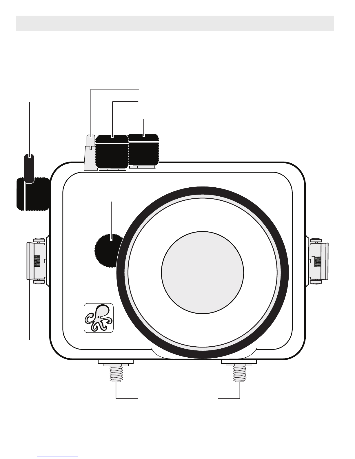
Parts of the Housing - Front View ..................................P. 5
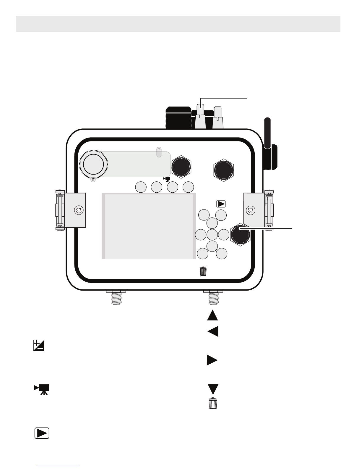
Parts of the Housing - Back View ..................................P. 6
Housing and Camera Setup ........................................P. 7
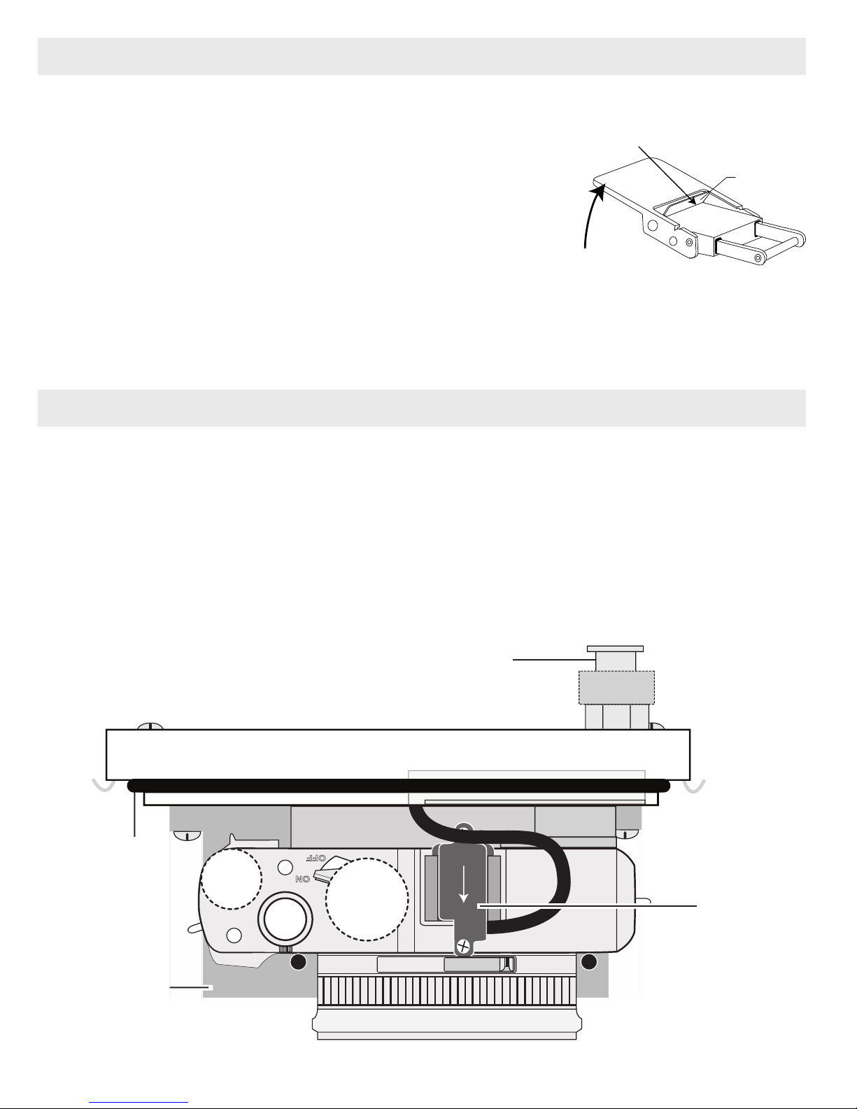
STEP 1 - Attach Tray and Handle to the Housing ..........P. 7
STEP 2 - nitial Camera Settings ....................................P. 8
STEP 3 - Opening the Housing ......................................P. 9
STEP 4 - Attach Hotshoe to Camera ..............................P. 9
STEP 5 - Attach Camera to Mounting Tray ....................P. 10
STEP 6 - Attach the Aperture Ring Gear to Lens ..........P. 11
STEP 7 - nstalling Camera in Housing ..........................P. 12
STEP 8 - Closing the Housing ........................................P. 12
STEP 9 - Final Housing Check ......................................P. 13
Strobe Compatibility ....................................................P. 13
kelite Housing Conversion Circuitry ..............................P. 14
Attaching a Sync Cord to the Housing ............................P. 14, 15
Attaching an kelite Strobe Arm to the Housing Handle..P. 15
Entering the Water ..........................................................P. 16
Recommended Accessories ......................................P. 16, 17
Maintenance ................................................................P. 18 - 21
Photo Tips ..................................................................P. 22
Troubleshooting ........................................................P. 23 - 25
2

3
Table of Contents - continued
Zoom Control ..................................................................P. 25
Spare Parts ..................................................................P. 26
Customer Support ......................................................P. 26
Limited Warranty ........................................................P. 26
Returning Products for Service ................................P. 27
Product Registration ..................................................Back Page
This product has been water pressure tested at the factory and is depth
rated to 200 ft (60 m). Thoroughly inspect and immerse the empty
housing completely in water before installing a camera. f any fogging
occurs or droplets of water enter the housing, do not install a camera.
Clean the main housing o-ring and retest to make sure that it is
watertight. Refer to the Troubleshooting section, page 23.
Please read your camera manual thoroughly to have a full
understanding of each camera function.
f you are new to underwater photography, be sure to read the Photo
Tips section, page 22.
Preparation

4
Controls ................................Controls for all camera functions except
................................................Diopter Adjustment Dial, Aspect Selector
................................................Switch, Front Control Ring, and
................................................Focus Selector Switch
Buoyancy ..............................Near neutral buoyancy in freshwater
Depth Rating..........................200 ft (60 m)
Strobe Connection................ kelite Digital TTL 5-pin Electrical
................................................Bulkhead plus TTL circuitry compatible with
................................................current model kelite DS strobes
Built-in Flash ........................None
Tray and Handle Weight ......11.5 oz (327 g)
Main O-Ring ..........................0110
Housing Dimensions ............7 x 6 x 6 in (18 x 15 x 15 cm)
................................................including projections
Housing Weight ....................4.7 lb (2.1 kg)
Flat Port Lens ........................Optical grade 3.9-inch glass
Specifications (no camera installed)
What’s in the Box
- Housing
- Waterproof Bulkhead Cap (on External Strobe connector)
- Tray with Quick Release Handle
- Port Cover
- Silicone Lubricant 1cc Tube
- Aperture Ring Gear

5
Parts of the Housing - Front View
Zoom Lever
Shutter
Button
Lens Port
External Tray Mounts
Lid Snap
Filter Button
ON/OFF
Housing controls are provided for all camera functions except t e Diopter
Adjustment Dial, Aspect Selector Switc , Front Control Ring, and Focus
Selector Switc
Aperture Ring

6
11
7
12
15
4
8 9
5
MENU
Fn3
6
10
13
123
16 17
Fn2 AE/FE
LOCK
Fn1 DISP
14
1. External Flash Connector
2. Shutter Speed Dial
3. Exposure Compensation Dial
4. Fn3 Button
5. Fn2 Button
6. Motion Picture Button
7. AF/AE Lock Button
8. Q. MENU Button
9. Playback Button
10. SO / UP
11. AF Mode / LEFT
12. ME U/SET
13. White Balance / R GHT
14. *Control Dial
15. Drive Mode / DOWN
16. Fn1/Delete Button
17. DISP. Display Button
iA Button
Parts of the Housing - Back View
*Control Dial: Note t at a small section of t e rubber disc is missing at t e end of t is
control. T is is normal and allows t e user to completely disengage t e control from t e
camera w en not in use. To disengage Control Dial from camera, rotate Dial to 6 o’clock
position. Rotate Control Dial W ite Dot to 12 o’clock position w en attac ing or
removing Housing Back from Housing Front.
Control Dial
White Dot

Using a 9/16” open/box end or socket Wrench (not supplied), firmly
tighten the External Tray to the Housing Base using the two 3/8-16 Nuts
supplied in the accessory package.
ote: Tray and Handle may be attached before or after the camera is
secured in the Housing. We recommend attaching it immediately to avoid
scratching table tops with the Tray Mounting Bolts.
External Tray & Handle
3/8-16 Nut
Wrench - not supplied
Housing and Camera Setup
STEP 1 - Attach Tray and Handle to the Housing
7
Tray Mounting Bolts

- Read your camera owner’s manual completely to familiarize yourself
with all the camera functions.
- nsert a fully charged camera battery and SD memory card.
- Turn camera on. Press “iA” Button to select “M” Manual shooting mode.
- Set Shutter speed to 1/60th second. For fast moving subjects, shutter
speed can be set to a maximum of 1/250th second when using a strobe.
Set aperture to F5.6, or F16 for macro photography (close-ups).
- Set SO to “200” and Aspect Ratio to 4:3 or other desired setting.
- In REC ME U:
Set Picture Size to “L”, AF to “AFS” AF Single, and AF Mode to “1-Area.”
Set Metering Mode to “Center Weighted.”
Set iDynamic and iResolution to “Standard” or other preferred setting.
Set Red-Eye Removal to “Off.”
Set Stabilizer based on your shooting habits and environment.
- I C ME U:
Set Shutter AF to “ON” and Half Press Release to “OFF.”
Set Quick AF to “ON” and Eye Sensor AF to “OFF.”
Set AF Assist Lamp to “OFF” and Focus/Release Priority to “FOCUS.”
Set Auto Review Duration Time to “5SEC.”
- I ME U:
Set Clock and Time. Format “ nitialize SD Card.”
- Set mage Quality to “L” 18M and mage Review to “8 sec.”
Set White Balance to “AWB.” For best results when not using a strobe,
use manual Custom White Balance and reset for each working
depth.
*All ot er camera functions not mentioned s ould be set to t e user
preference.
STEP 2 - Initial Camera Settings (before placing camera in housing)
Setup your camera for underwater use and t en adjust your settings once underwater.
8

9
STEP 3 - Opening the Housing
Lid Snaps have a Lock.
1. Push Lid Snap Locks forward and lift as shown.
Open opposing Lid Snaps simultaneously. Keep
pressure on the Lid Snaps so they do not fly
open quickly. Some Lid Snaps ave a lot of
spring tension once t ey go over center, so keep
a firm grip on eac Lid Snap. Lid Snaps may also
be opened one at a time.
2. Remove the Housing Back.
Push Forward Lid
Snap
Lock
Lift
STEP 4 - Attach Hotshoe to Camera
ON
Front
Ikelite
Panasonic
DMC-LX100
OFF
Diagram A
Hotshoe
Connector
Mounting Tray
Housing Back
O-ring
External Strobe Connector
& Waterproof Cap
(Do not remove underwater)
1. The Mounting Tray for the camera is secured to the housing back.
Position the camera above the Mounting Tray.
2. Slide and push the housing Hotshoe Connector forward into the Camera
Hotshoe Mount
until it stops,
Diagram A
. Make sure the Hotshoe is all
the way forward in the Mount. This should be done before the camera is
secured with the mounting bolt.

STEP 5 - Attach Camera to Mounting Tray
1. Using a coin or screwdriver (preferred), secure the camera with the Tray
Mounting Bolt which threads into the camera’s tripod socket, Diagram B.
CAUTIO :
Do not cross t read or overtig ten t e Tray Mounting Bolt as you may
damage t e camera tripod socket t reads.
2. * Control Dial “cut away.” Rotate control to match Diagram B below. This
allows for proper clearance when attaching the housing back to the
housing front.
10
Lumix
L
Tray Mounting Bolt
Aperture Ring
Bump-out
* Control Dial “cut away.” Rotate as s own w en attac ing ousing back to ousing
front. Control Dial W ite Dot will be in t e 12 o’clock position. W en not in use, rotate
Control Dial w ite dot to t e 6 o’clock position so “cut away” is over t e camera dial and
not contacting t e camera.
Diagram B
Housing
Back

11
Lumix
L
Aperture Ring Gear
(properly installed)
STEP 6 - Attach Aperture Ring Gear to Lens
1. Rotate camera Aperture Ring so the Bump-outs, Diagram B, Page 10,
line up between the Aperture Ring Gear
Foam Strips, Diagram C.
2. With the white dot at the 12 o’clock
position, gently slide the Aperture Ring
Gear over the camera Aperture Ring. The
camera’s Aperture Ring Bump-outs go
between the the Aperture Ring Gear foam
strips. The Gear is a “press fit” over the
lens. When properly installed, the Foam
Strips willl be flush with the Aperture Ring
Bump-outs, Diagram D.
3. Rotate Aperture Ring Gear back and forth to test function.
Foam Strip
White Dot
Diagram C
Diagram D

12
1. Pull out on each housing control until it stops. This will get the controls
out of the way for installation of the camera. Make sure the Movie
Button knob is pulled out and the control is facing toward the bottom of
the housing.
2. Remove camera lanyard from camera if attached.
3. Place the Housing Front face down in your lap.
4. Gently guide the Housing Back with camera attached into the Housing
Front at a slight angle so the Aperture Ring Gear and Housing Gear
engage properly. Visually check to see that the Gears are properly
engaged and test their function.
STEP 7 - Installing Camera in Housing
STEP 8 - Closing the Housing
1. Once the back is properly
installed, the o-ring should touch
the housing all the way around.
There should be an even gap on
each side of the housing between
the housing and the back.
2. Lift the lid snaps so they are
extended and place each lid snap
into the corresponding hook on
the housing back.
3. To close the housing, push down on
the opposing lid snaps simultaneously
until they snap into place. Be sure
they are down far enough to engage
the Lid Snap Lock. The o-ring seal
should now appear as a solid black
line from the back of the housing.
Housing Back
O-ring
Even gap on
all four sides
Lid Hook
Lid
Snap
Lid Snap Lock

STEP 9 - Final Housing Check
The clear housing permits instant visual inspection of the camera and
sealing surfaces as well as complete monitoring of controls and camera
LCD screens. This housing has been factory water pressure tested to
200 ft (60 m).
Once the housing is closed, recheck the o-ring seal. Double check the
gap between the housing back and the housing. t should be even all the
way around the housing.
Look through the clear plastic back at the o-ring. You should see a
darkened area or solid black line where the o-ring is compressed against
the housing back. f you do not see an even black compression seal all
the way around the back, open the lid snaps, reseat the housing back and
close the lid snaps. Visually check the seal again.
13
Strobe Compatibility
- AF35........................no
- DS50........................yes, above serial number 70000
- DS51........................yes
- DS125......................yes, above serial number 5000
- DS160, DS161 ........yes
- DS200......................yes, above serial number 7163
- Non- kelite ..............yes, manual flash exposure only

Ikelite Housing Conversion Circuitry
This small compact housing has kelite designed and patented
Conversion Circuitry built right in. The Conversion Circuitry provides real
TTL flash exposure when used with kelite DS series strobes. Once a
DS series strobe is attached to the External Strobe Connector, the
conversion circuitry is automatically powered after the strobe is turned
on. Once attached, turn the strobe on first before turning on the camera.
The circuitry cannot be powered up or used by non- kelite strobes,
however, non- kelite strobes can be fired manually with the correct cord.
Attaching a Sync Cord to the Housing - Diagram E, Page 15
14
The Housing Bulkhead Connector is designed to accept sync cords with
kelite 5 pin connector fittings.
1. Lightly lubricate the Sync Cord O-ring. Use ONLY kelite lubricant
(supplied with housing).
2. Remove Bulkhead Cap from Housing Bulkhead.
3. Line up the Sync Cord Pins with the corresponding Bulkhead
Receptacles. Gently insert Sync Cord into Bulkhead. DO NOT force this
installation. If t e Sync Cord does not seat properly inside t e Bulk ead,
t en t e Pins and Receptacles are improperly aligned (repeat Step 3).
4. Tighten the Knurled Nut snugly using your ndex finger and thumb. DO
NOT use pliers or other tools to tighten the Knurled Nut.
- Always remove the Sync Cord from your Housing when not in use and
replace the Bulkhead Cap.

To attach an kelite Arm to your
Housing Handle, depress the
spring-loaded Handle Push
Button until it stops. Gently slide
the pronged end of the kelite Arm
into the hole in the top of the
Handle as shown, Diagram F.
When the kelite Arm is properly
seated, the Handle Push Button
will return to its starting position.
kelite Arm
Handle Push
Button
Housing Handle
Attaching an Ikelite Strobe Arm to the Housing Handle
15
Diagram F
Attaching a Sync Cord to the Housing - Diagram E
Housing
Bulkhead
Bulkhead
Cap
Sync Cord O-ring
Sync Cord Pin
Knurled Nut
kelite TTL
Sync Cord
Diagram E

16
As soon as you enter the water, take a moment and check to see that
the housing is properly sealed. We recommend you first water test the
housing with no camera inside to assure a safe and watertight
environment.
Next, check to see if there are any bubbles on the face of the lens port.
f there are, take your finger and remove them. f there are bubbles on
the lens port they can produce soft focus spots in your photos or video.
Entering the Water
Recommended Accessories
External Color Correcting UR/Pro Filters
(Blue Water or Green Water)
Color filters such as the UR-Pro Filter replace
some of the reds, oranges and more natural
tones that would otherwise be lost underwater.
Effective in relatively shallow, sunny conditions,
and available for tropical blue water and green
water settings. For optimum results use in
combination with custom (manual) white
balance.
For available light use only. Not recommended
when using external strobes.
UR-Pro Filter Lens Port
WD-4 Wide-Angle Conversion Dome 6430.4
The removeable WD-4 corrects light refraction underwater,
restoring the camera’s original angle of coverage. Approximately
3/4 of the camera's zoom range from the camera’s widest angle
setting can be used with the dome in place. Slight vignetting may
occur at camera’s widest angle setting.

External Macro Adaptor 9306.82
Allows attachment of 67mm threaded macro lenses from non
and Epoque. NOT for use with 67mm threaded wide-angle lenses.
ote: Other than the 6430.4 and 9306.82, no other accessory lenses or
adaptors can be used with this housing.
Recommended Accessories - continued
Tray + Dual Handles 9523.64
Add stability and gripping point(s) for comfortable use of the housing.
Add a second strobe to eliminate shadows and evenly light your
subjects.
DS161 Strobe, Sync Cord + Ball Arm Mark II Kit
The Panasonic LX100 camera does not feature a built-in flash. We
recommend a DS161 Strobe Kit to combine power with wide angle
coverage to adequately light your subjects. The DS161 quality of light is
exceptional due to a round flash tube and custom powder coated
reflector designed specifically to deliver the softest, most even coverage
possible. Add a second DS161 to eliminate shadows and provide
balanced lighting.
Video Lighting
External video lights such as the 2101 Vega Video + Photo Light add
color when using the video/movie mode of your camera. Primary video
lights are specially color balanced to provide natural tones.
Additional Accessories
- 2602.3 Quick Release Handle Kit for GoPro
- Gamma LED Flashlight
A full range of accessories are available to support your housing. Please
visit www.ikelite.com to see the most current information about
recommended accessories for your housing.
17

Maintenance
kelite provides silicone lubricant with the housing. We recommend you use
only kelite lubricant on kelite products. Other brands may cause the main
housing o-ring to swell and not seal properly.
Use only enough lubricant to lightly cover the main housing o-ring or
lubricate a sticky control. Wipe off any excess lubricant with a clean
cloth. Lubricant is not a sealant; it is used to reduce friction. Excessive
lubricant can collect sand and dirt which may interfere with proper
sealing.
CAUTIO :
ever use spray lubricants as the propellant ingredient can cause
the plastic housing to crack or o-rings to swell.
Treat the glass in the lens port as a camera lens. After use, rinse and
gently dry the outside lens port to avoid water spotting. To clean, use a
mild soap solution or lens cleaner. t is NOT necessary to remove the
Port for cleaning. Do not rinse inside the Port.
Do not use alcohol or window cleaner on the Lens Port.
Lens Port
Lubricant
18

Your kelite Digital Housing should be given the same care and attention
as your other photographic equipment. n addition to normal
maintenance, we recommend that the housing be returned to kelite
periodically to be checked and pressure tested.
-Do ot leave the camera and housing in direct sunlight for prolonged
periods. Heat may damage the camera.
-Do ot ship the camera in the housing.
- Before using the housing, always check the tightness of the set screw
in each control knob. Check each control gland penetrating the housing
to make sure they are tight. There is a slight chance that either could
vibrate loose during travel.
- Keep the main housing o-ring clean and lightly lubricated. To lubricate,
remove the o-ring from the back. Put a small amount of lkelite lubricant
on your fingers. Pull the o-ring through your fingers to apply a thin
coating of lubricant. Only apply enough lubricant to make the o-ring feel
slick. Do ot stretch the o-ring. This light coating of lubricant will help
to keep the o-ring from drying out and will help to show a dark sealing
line when the housing back is properly sealed.
- Keep the area where the o-ring fits and the sealing surface of the
housing clean.
- Rinse the housing exterior thoroughly in freshwater after each saltwater
use. Depress push buttons repeatedly in freshwater to eliminate trapped
saltwater. Dry with a soft cloth. Dry lens port to eliminate water spotting.
After several uses in saltwater, soak the housing exterior in a mild soap
solution; rinse and dry before storing. When storing the housing, remove
the back o-ring, lightly lubricate, and place in a plastic bag. Place the
plastic bag with o-ring inside the housing for safe keeping.
- f removing a housing push button, Do ot re-use the E-clip. Contact
kelite for replacement E-clips (part 0319.12).
- Leave lid snaps in the open position when not using the housing for
extended periods.
Housing Maintenance
19

20
Ikelite controls are designed to provide years of reliable service wit
minimal maintenance.
- Push button controls normally require no maintenance other than rinsing
in freshwater after saltwater use. Depress each push button in
freshwater several times to eliminate trapped saltwater. f a push button
control becomes difficult to push or if it sticks when depressed, soak the
housing in luke warm freshwater. After a few minutes, operate the push
button. f this does not correct the problem, return the housing to kelite
for maintenance. f you are on a trip and unable to return the housing
immediately, a push button may be lubricated by pressing and holding
the push button all the way in. Then, use your finger or other small
non-metal object to place a small amount of lube at the base of the shaft
inside the housing. Press and release the push button several times until
the lube is worked up into the o-ring.
After completing this procedure, close
the housing and submerge it in water
without the camera i nside. Check the
control for watertightness.
Control Maintenance
Diagram G
Apply kelite Lube here
Table of contents