Illuminite Illumipod 18 IP Optic RGB User manual

Ilumipod 18 IP Optic Series
User Manual
Ilumipod18IPOpticRGB
Ilumipod18IPOpticVW

Edition Notes
Ilumipod 18 IP Optic Series User Manual Rev. 08
Edition Notes
The Ilumipod 18 IP Optic Series User Manual Rev. 08 covers the description, safety precautions,
installation, programming, operation, and maintenance of all the Ilumipod 18 IP Optic Series.
ILUMINARC
®
released this edition of the Ilumipod 18 IP Optic Series User Manual Rev. 08 in
August 2011.
Trademarks
The ILUMINARC
®
logo, the ILUMINARC
®
name and all other trademarks in this document
related to services or products by ILUMINARC
®
are trademarks owned or licensed by
ILUMINARC
®
, its affiliates or subsidiaries. Any other product names, logos, brands, company
names, or trademarks featured or referred to within this document are the property of their
respective trademark holders.
Copyright Notice
The entire content of this document, except where applicable and unless otherwise noted, is solely
owned by ILUMINARC
®
, a wholly owned trademark of CHAUVET & Sons Inc.
© Copyright 2011 ILUMINARC®.
All rights reserved.
Electronically published by ILUMINARC
®
in the United States of America.
Manual Usage
ILUMINARC
®
authorizes its customers to download and print this manual for professional
information purposes only. ILUMINARC
®
expressly prohibits the usage, copy, storage,
distribution, modification, or printing of this manual or its content for any other purpose without
its written consent.
Document Printing
For better results, print this document in color, on letter size paper (8.5 x 11 inches), double sided.
If using A4 paper (210 x 297 mm), configure your printer to scale the content of this document to
A4 paper.
Intended Audience
Any person in charge of installing, operating and/or maintaining the Ilumipod 18 IP Optic Series
should read the Guide that shipped with it and this manual in their entirety before installing,
operating, or maintaining this product.
Disclaimer
ILUMINARC
®
believes that the information contained in this manual is accurate in all respects.
However, ILUMINARC
®
assumes no responsibility for any error or omissions in this document.
ILUMINARC
®
reserves the right to revise this document and to make changes from time to time
in the content hereof without obligation of ILUMINARC
®
to notify any person or company of
such revision or changes. This does not constitute in any way a commitment by ILUMINARC
®
to
make such changes. ILUMINARC
®
may issue a revision of this manual or a new edition of it to
incorporate such changes.
Document Revision
The Ilumipod 18 IP Optic Series User Manual Rev. 08 supersedes all previous versions of this
manual. Please discard any older versions of this manual you may have, whether in printed or
electronic format, and replace them with this version.

Table of Contents
Ilumipod 18 IP Optic Series User Manual Rev. 08 i
Table of Contents
1. Introduction......................................................................................................1
What Is in the Box........................................................................................................ 1
Unpacking Instructions................................................................................................. 1
Text Conventions ......................................................................................................... 1
Safety Notes................................................................................................................. 2
Personal Safety...................................................................................................................2
Mounting and Installation.....................................................................................................2
Power and Wiring................................................................................................................2
Operation.............................................................................................................................2
2. Product Description ........................................................................................3
Common Features........................................................................................................ 3
Ilumipod 18 IP Optic SpectraWhite™ Features...................................................................3
Ilumipod 18 IP Optic RGB Features ....................................................................................3
Product Overview......................................................................................................... 4
Product Dimensions..................................................................................................... 5
3. Installation........................................................................................................6
AC Power ..................................................................................................................... 6
Input Voltage and Frequency...............................................................................................6
Power Consumption............................................................................................................6
Power Wiring.......................................................................................................................6
Signal Wiring .......................................................................................................................6
External Wiring............................................................................................................. 6
Power Distribution ...............................................................................................................7
Signal Distribution................................................................................................................7
Controllers.................................................................................................................... 8
DMX Controller....................................................................................................................8
ILUMICON...........................................................................................................................8
Ilumicode.............................................................................................................................9
Mounting..................................................................................................................... 10
Orientation.........................................................................................................................10
Rigging..............................................................................................................................10
Procedure..........................................................................................................................10
4. Operation........................................................................................................11
Ilumicode.................................................................................................................... 11
Ilumicode Panel Description..............................................................................................11
Menu Map .................................................................................................................. 11
SpectraWhite™ Functions Menu Map...............................................................................11
RGB Functions Menu Map ................................................................................................12
Programming.............................................................................................................. 13
DMX Personality................................................................................................................13
DMX Starting Address.......................................................................................................13
Dimmer..............................................................................................................................13
ILUMICON Control ............................................................................................................14
Static Color........................................................................................................................14
Color Calibration................................................................................................................14
Color..................................................................................................................................14
Reset.................................................................................................................................14
DMX Values ............................................................................................................... 15
ARC 1................................................................................................................................15
ARC 1 + D.........................................................................................................................15
ARC FULL.........................................................................................................................15
VW.....................................................................................................................................16
VW + D..............................................................................................................................16
SOLID................................................................................................................................16

Table of Contents
ii Ilumipod 18 IP Optic Series User Manual Rev. 08
5. Technical Information ...................................................................................17
Product Maintenance ................................................................................................. 17
Product Repairs.......................................................................................................... 17
Troubleshooting Guide............................................................................................... 18
Photometrics .............................................................................................................. 19
LED Disclaimer........................................................................................................... 22
LED Life.............................................................................................................................22
LED Binning.......................................................................................................................22
Color Rendering Index (CRI).............................................................................................22
Returns Procedure..................................................................................................... 23
Claims......................................................................................................................... 23
Contact Us.................................................................................................................. 23
Technical Specifications............................................................................................. 24
Ilumipod 18 IP Optic RGB .................................................................................................24
Ilumipod 18 IP Optic VW ...................................................................................................25
Introduction
Ilumipod 18 IP Optic Series User Manual Rev. 08 1
1. Introduction
This icon
indicates useful,
although non-
critical information.
This icon
indicates
important
installation or
configuration information.
Failure to comply with this
information may prevent
the product from
functioning correctly.
This icon
indicates critical
installation,
configuration, or operation
information. Failure to
comply with this
information may render
the product partially or
completely inoperative,
damage third-party
equipment, or cause harm
to the user
The term “DMX”
used throughout
this document
refers to the USITT
DMX512-A transmission
protocol.
What Is in the Box
One Ilumipod 18 IP Optic product (RGB or VW)
Warranty Card
Quick Reference Guide
Unpacking Instructions
Immediately upon receiving a product from ILUMINARC
®
, carefully unpack the carton. Check
the contents of the box to ensure that all parts are included and in good condition. If any part
appears damaged from shipping, or if the carton shows signs of mishandling, see the Claims
section in the Technical Information chapter.
Text Conventions
Convention Meaning
1~512 A range of values in the text
50/60 A set of mutually exclusive values in the text
“ILUMICON UM” The name of another publication or manual
<SET> A button on the products control panel
Settings A product function or a menu option
MENU > Settings A sequence of menu options
1~10 A range of menu values from which to choose in a menu
Yes/No A set of two mutually exclusive menu options in a menu
ON A unique value to enter or select in a menu
Introduction
2 Ilumipod 18 IP Optic Series User Manual Rev. 08
There are no
user serviceable
parts inside this
product. Any reference to
servicing it you may find
from now on in this User
Manual will only apply to
properly ILUMINARC
®
certified technicians. Do
not open the housing or
attempt any repairs
unless you are Certified to
do so.
Please refer to all
applicable local
codes and
regulations for the proper
installation of this product.
Keep this manual
for future
consultation. If
you sell this product to
another user, make sure
that they also receive this
manual.
In the unlikely
event that your
Ilumipod 18 IP
Optic Series may require
service, please contact
ILUMINARC
®
Technical
Support.
Safety Notes
Please read all the following safety notes carefully because they include important information
on how to install, use, and maintain this product safely.
Personal Safety
Avoid direct eye exposure to the light source while the product is on.
Always disconnect this product from its power source before servicing.
Always connect this product to a grounded circuit to avoid the risk of electrocution.
Do not touch this product’s housing when operating because it may be very hot.
Mounting and Installation
The Ilumipod 18 IP Optic Series are for outdoor use and can work while submerged in
up to 1 m of water (IP67). However, do not submerge deeper than 1m for more than (30)
thirty minutes.
Make sure there are no flammable materials close to this product while operating.
When hanging this product, always secure it to a fastening device using a safety cable
(not provided).
Power and Wiring
Always make sure that you are connecting this product to the proper voltage, as per the
specifications in this manual or on the product’s sticker.
Never connect this product to a dimmer pack.
Make sure that the power input cable is not cracked, crimped, or damaged.
Operation
The maximum ambient temperature (Ta) is 104° F (40° C). Do not operate this product
at a higher temperature.
In case of a serious operating problem, stop using this product immediately!

Installation
Ilumipod 18 IP Optic Series User Manual Rev. 08 3
2. Product Description
Other than their
LED configuration
and programming
features, these
two products share the
same dimensions, as well
as the installation, wiring,
and troubleshooting
procedures.
The lenses in
these two
products are non-
changeable.
Therefore, make sure to
use the right product
order code for the desired
lens angle.
The Ilumipod 18 IP Optic Series includes two products: Ilumipod 18 IP Optic RGB and
Ilumipod 18 IP Optic VW.
Common Features
Remotely addressable DMX-512 LED wash light
IP67 ingress protection
IP67 stainless steel gland nuts for cable entry
Humidity controlling gore valve
Cast aluminum housing
ILUMICON compatible
Five distinct dimming curves
Ilumipod 18 IP Optic VW SpectraWhite™ Features
Operating modes:
1-channel: Dimmer
2-channel: Warm white, cool white
3-channel: Warm white, cool white, dimmer
18 x 1 W (350 mA) Warm White and Cool White LEDs
Installed (non-changeable) optical system:
30lenses Product order code: 11018010
Ilumipod 18 IP Optic RGB Features
Operating modes:
3-channel: RGB control
4-channel: RGB, dimmer
7-channel: RGB, dimmer, macro, strobe, dimming speed
High power 1 W (350 mA) Red, Green, and Blue LEDs
Ilumicode compatible
Blackout/static/dimmer/strobe/pulse
Installed (non-changeable) optical system:
15lenses Product order code: 11018001
30º lenses Product order code: 11018004

Installation
4 Ilumipod 18 IP Optic Series User Manual Rev. 08
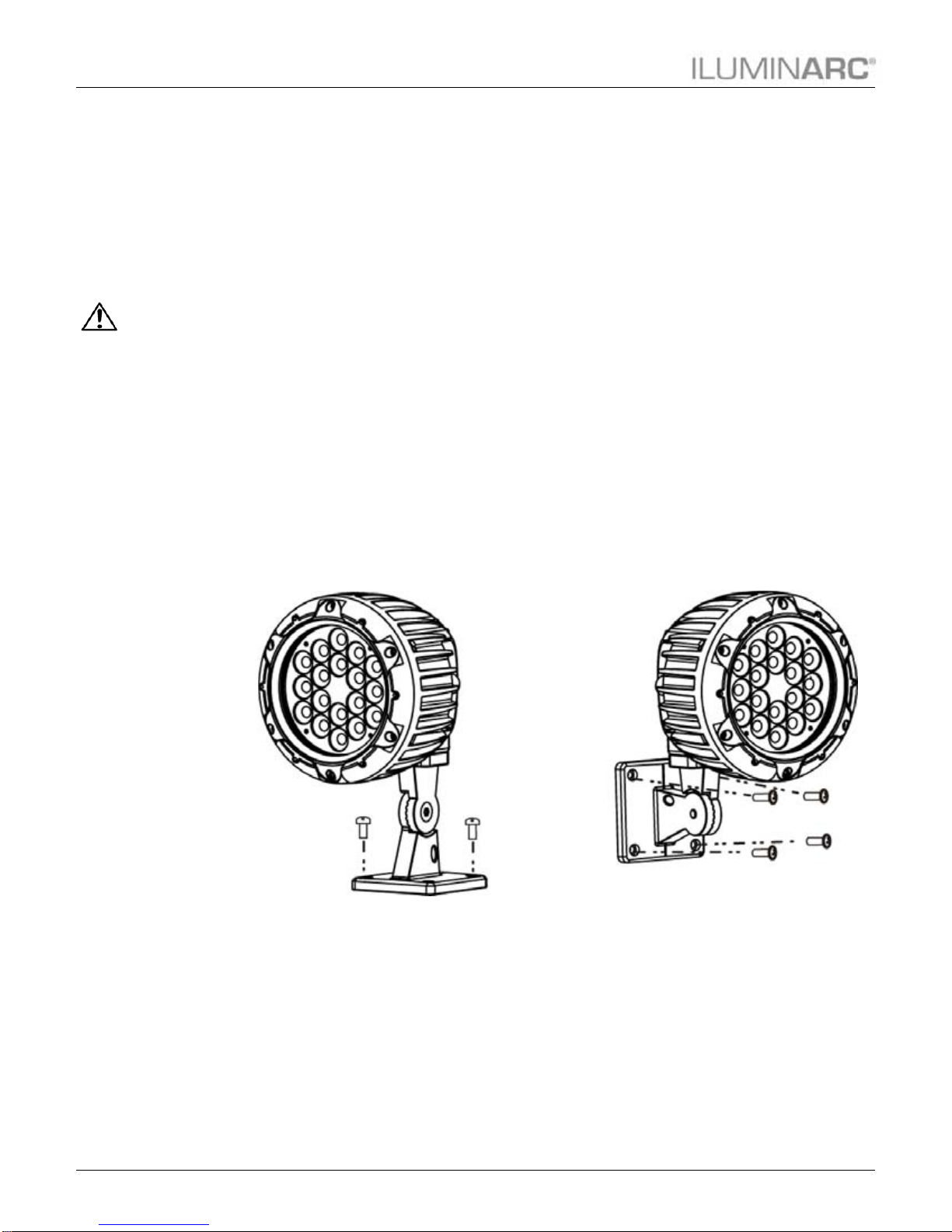
Product Overview
Mounting
Bracket
Gore Valve
Power In
Bracket
Adjustment
Cable tie
location
Safety cable
attachment Front of
product
Installation
Ilumipod 18 IP Optic Series User Manual Rev. 08 5
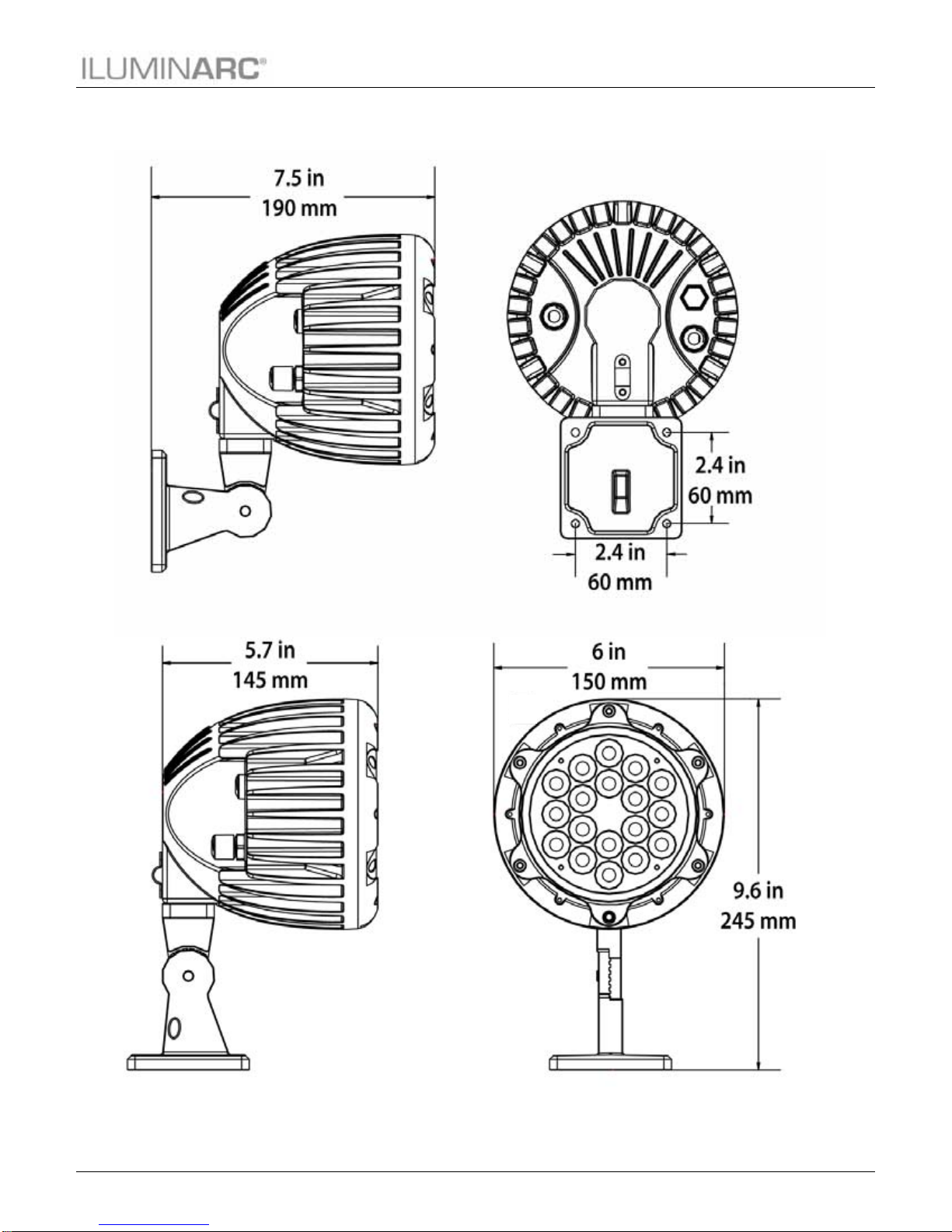
Product Dimensions

Installation
6 Ilumipod 18 IP Optic Series User Manual Rev. 08
3. Installation
Always connect
the Ilumipod 18
IP Optic Series to
a protected circuit with an
appropriate electrical
ground to avoid the risk of
electrocution or fire.
Never connect
the Ilumipod 18
IP Optic Series to
a rheostat (variable
resistor) or dimmer circuit,
even if the rheostat or
dimmer channel serves
only as a 0 to 100%
switch.
Make sure to
connect the 18 IP
Optic Series
product to a power line
with the proper voltage
and frequency, as per the
specifications in this
manual or on the
product’s sticker.
The listed
current rating
indicates the
maximum current draw
during normal operation.
The signal cable
must match or
exceed the
electrical characteristics
of the Belden® 9841
cable for EIA RS-485
applications. You may
also use CAT5, 5e, or
CAT6 LAN cable.
If you choose to
bury the power or
signal distribution
boxes, make sure that
they are IP67 rated or
greater.
AC Power
Input Voltage and Frequency
The products in the Ilumipod 18 IP Optic Series have an auto-ranging power supply with an
input voltage range of 100~240 VAC, 50/60 Hz.
Power Consumption
To determine the power requirements for the Ilumipod 18 IP Optic Series, see the label
affixed to the side of the product. Alternatively, you may refer to the corresponding
specifications chart in the Technical Information chapter of this manual.
The listed current rating indicates the maximum current draw during normal operation.
Power Wiring
To provide AC power for any of the Ilumipod 18 IP Optic Series, you can connect the bare-
ended IP67 rated power cable from the product to an IP67 rated power connector or use an
IP67 rated junction box. In this case, make sure to use IP67 rated conduit or direct buried
cable (DBC)
Connection Wire (US) Wire (Europe)
Live Black Brown
Neutral White Blue
Ground Green/Yellow Green/Yellow
AC Power Input Wiring
Signal Wiring
To provide signal for any of the Ilumipod 18 IP Optic Series, You can connect the bare-
ended IP67 rated signal cable from the product to two IP67 rated signal connectors (DMX in
and DMX Out) or use an IP67 rated junction box. In this case, make sure to use IP67 rated
conduit.
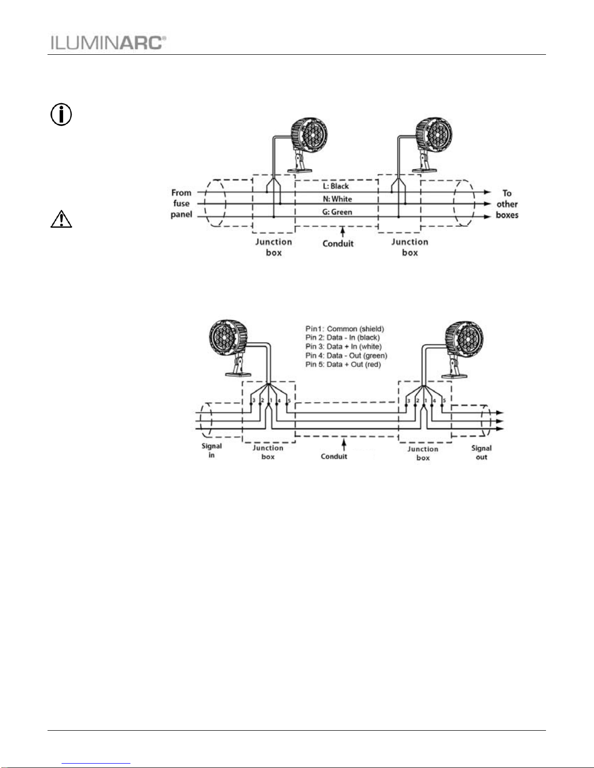
External Wiring
You must run AC power and signal wires from the respective AC and signal distribution boxes
into each of the Ilumipod 18 IP Optic Series products.
Installation
Ilumipod 18 IP Optic Series User Manual Rev. 08 7
Always keep the
power cables
away from the
signal cables by
running them in different
conduits and using
separate distribution
boxes.
Make sure to use
power and signal
cables with the
indicated outer diameters
to ensure that the
corresponding gland nut
makes full contact with
the cable’s external
insulation. This is required
to keep the products IP67
rating when fully adjusted.
Power Distribution
Connect the bare-ended power cable from the product to a power distribution box as
indicated below.
Signal Distribution
Connect the bare-ended signal cable from the product to a signal distribution box as
indicated below.
Installation
8 Ilumipod 18 IP Optic Series User Manual Rev. 08
If you have not
configured the
DMX starting
address and DMX
mode for each product,
they will all use their
default values. This
means that all products
will operate in unison.
Refer to the
Operation chapter
to learn how to
enable the
Ilumipod 18 IP Optic RGB
to operate with the
ILUMICON controller.
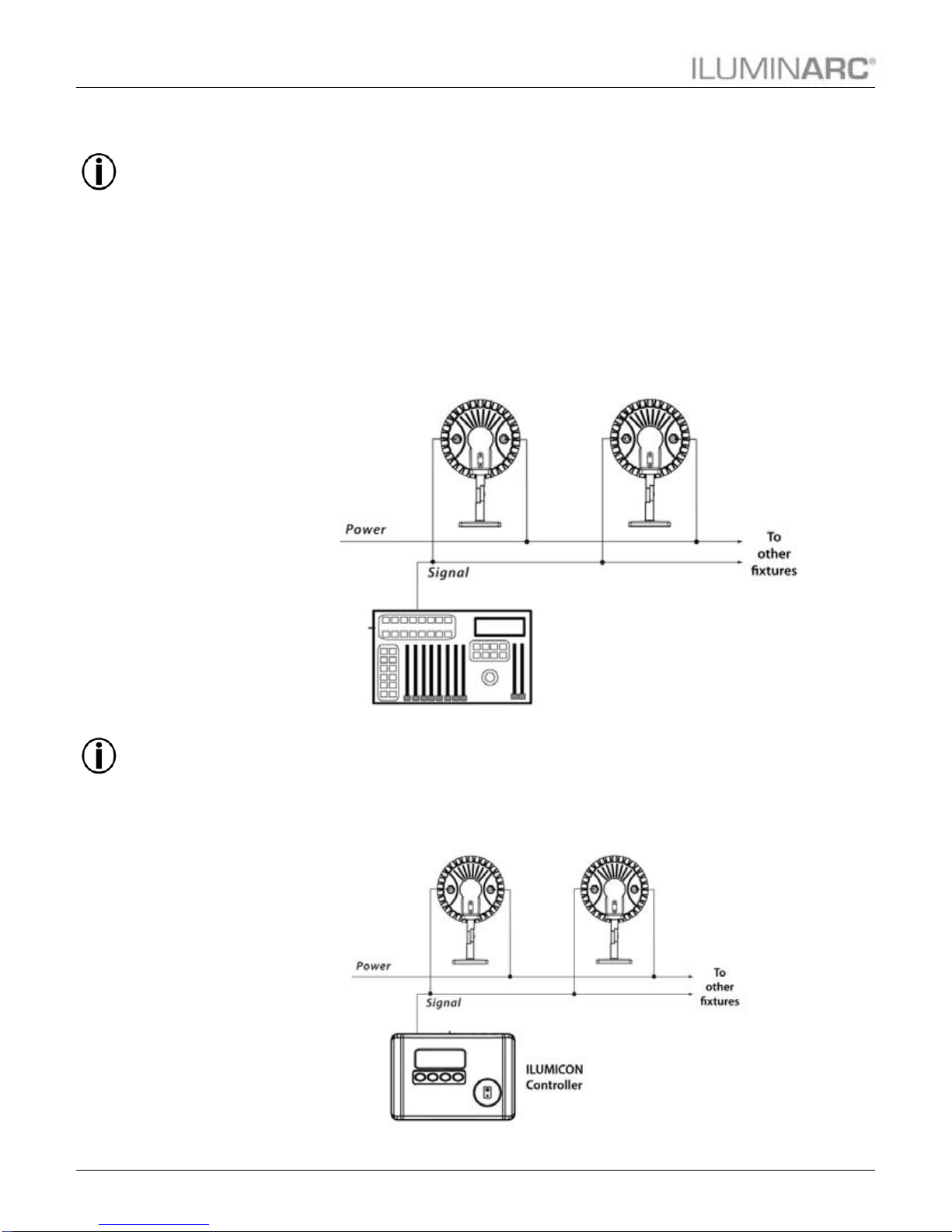
Controllers
The products in the Ilumipod 18 IP Optic Series can operate with a standard DMX controller or
the Ilumicode controller. The sections below will show you how to connect these products to
the corresponding controllers. The instructions to operate these products with each of the above
controllers are in the Operation chapter of this manual.
DMX Controller
The Ilumipod 18 IP Optic Series can work with a standard DMX controller. The channel
assignments will depend on the chosen personality (see the corresponding Menu Map on
pages 11and 12) and the DMX address assigned to each product (see Programming on page
13).
The figure below illustrates how to connect the DMX controller to the Ilumipod 18 IP Optic
Series products.
ILUMICON
The Ilumipod 18 IP Optic RGB can also work with the ILUMICON controller instead of a
standard DMX controller. Please refer to the ILUMICON User Manual to learn how to use
this controller with the Ilumipod 18 IP Optic Series product.
The figure below illustrates how to connect the ILUMICON controller to the Ilumipod 18 IP
Optic Series.
DMX 512-A
Controller

Installation
Ilumipod 18 IP Optic Series User Manual Rev. 08 9
To assign
individual DMX
addresses to
each product, you
must connect the
Ilumicode controller to
each product, individually.
ILUMINARC®
suggests that you
connect no more
than 20 products
in this mode and keep the
total distance to less than
60 m (197 ft). Otherwise,
you might need to use an
optically isolated signal
amplifier.
Ilumicode
The Ilumipod 18 IP uses the Ilumicode addresser for configuration purposes. The diagram
below shows how to connect the Ilumicode to this product.
Note that this connection will control multiple products at the same time, all having the
same DMX address.
ILUMICODE
Addresser
Installation
10 Ilumipod 18 IP Optic Series User Manual Rev. 08
Make sure to
mount this
product away
from any flammable
material as indicated in
the Safety Notes.
Mounting
Before mounting this product, read and follow the safety recommendations indicated in the
Safety Notes section (page 2 of this manual).
Orientation
Always mount this product in a safe position making sure there is adequate room around it
for ventilation, configuration, and maintenance.
Rigging
The Ilumipod 18 IP Optic Series consist of a cast aluminum mounting bracket with four (4)
5mm screw holes. ILUMINARC
®
recommends following the general guidelines below
when mounting the Ilumipod 18 IP Optic Series products.
When selecting an installation location, consider ease of access to the product for
operation, programming adjustments, and routine maintenance.
Never mount the product in places where restricted ventilation may affect it.
Make sure that the location where you are mounting the product can support its weight.
Please see the Technical Specifications section of this manual for the weight requirement
of this product.
Procedure
The Ilumipod 18 IP Optic Series come with cast aluminum mounting brackets which you
can attach to a flat mounting surface. These brackets also serve as floor or wall mount
supports. You will have to use four mounting points per product.
Technical Information
Ilumipod 18 IP Optic Series User Manual Rev. 08 11
4. Operation
When you scroll
through the
menu levels, you
will see many of
them that do not
correspond with this menu
map. These levels are for
RGB products only.
If you scroll after
STRB, you will
see the RED,
GREN, BLUE,
and AMBE colors.
Disreguard them as they
do not work with the VW
products.
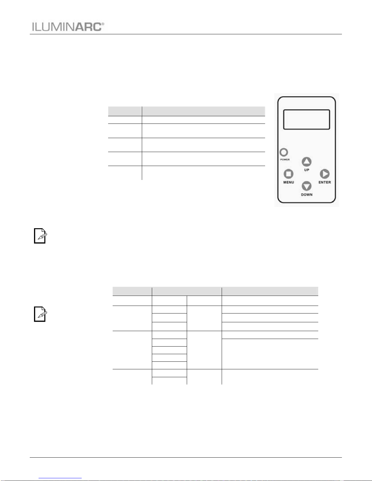
Ilumicode
The products in the Ilumipod 18 IP Optic Series use an external controller, the Ilumicode
addresser, to change their configuration.
Ilumicode Panel Description
Menu Map
The products in the Ilumipod 18 IP Optic Series have distinct menu maps based on the colors
they produce, whether RGB or White. The Ilumicode addresser controls the functions for both
types of products.
SpectraWhite™ Functions Menu Map
This menu map shows you which parameters of the Ilumicode controller correspond to the
Ilumipod 18 IP Optic Series VW product.
Main Level Programming Levels Description
DMX 001~512 N/A Sets the DMX starting address
PERSON
VW
N/A
3-channel: SpectraWhite control
VW+D 4-channel: SpectraWhite control + dimmer
SOLID 1-channel: dimmer
DIMMER
OFF
N/A
Dimmer work in linear mode
DIM 1
Dimmer works in non-linear mode, from fast to
slow.
DIM 2
DIM 3
DIM 4
STATIC COOL 0~255 Configures the static color and effect
WARM
Button Function
<MENU> Exits from the current menu or function
<ENTER> Enables the currently displayed menu or sets the
currently selected value into the selected function
<UP> Navigates upwards through the menu list and increases
the numeric value when in a function
<DOWN> Navigates downwards through the menu list and
decreases the numeric value when in a function
<POWER> Turns the unit on. The unit will turn off automatically
after 30 seconds of inactivity.

Technical Information
12 Ilumipod 18 IP Optic Series User Manual Rev. 08
When you scroll
through the
menu levels, you
will see many of
them that do not
correspond with this menu
map. These levels are for
SpectraWhite products
only.
If you scroll after
STRB, you will
see the AMBE,
COOL and
WARM colors. Disreguard
them as they do not work
with the RGB products.
RGB Functions Menu Map
Main Level Programming Levels Description
DMX 001~512 N/A Sets the DMX starting address
PERSON
ARC 1
N/A
3-channel: RGB control
ARC 1 + D 4-channel: RGB control + dimmer
ARC FULL 7-channel: RGB control, dimmer, color macro,
strobe, dimmer speed
REMOTE Allows using the ILUMICON unit
SOLID 1-channel: dimmer
CALIB WHITE (1~11) RED
GREN
BLUE 0~255
Determines the white balance for the color
macros
RGBTOW Determines the white balance when RGBTOW
is active
DIMMER
OFF
N/A
Dimmer work in linear mode
DIM 1
Dimmer works in non-linear mode, from fast to
slow.
DIM 2
DIM 3
DIM 4
STATIC
RED
0~255 Configures the static color and effect
GREN
BLUE
STRB
SETTINGS COLOR
OFF Maximum output, unbalanced white
RGBTOW White output is as per CALIB > RGBTOW
settings
UC
Output matches that of product’s previous
versions
RESET NO/YES Resets unit to factory default settings
1.

Technical Information
Ilumipod 18 IP Optic Series User Manual Rev. 08 13
Make sure to
press <ENTER>
after selecting an
option. Otherwise, the
product will not save the
new setting. In this case,
the Ilumicode’s display
will show “SEND…”
The DMX Starting
Address setting
works with all but
the REMOTE
personality.
Programming
Carry out all the programming procedures indicated below from the control panel. Refer to the
Menu Map in pages 11 and 12 to learn how the menu options relate to each other.
Use <ENTER> and <MENU> to change levels in the Menu Map. This is equivalent to move
right and left respectively. Use <UP> and <DOWN> to move vertically within the Menu Map
options.
DMX Personality
1. Go to PERSON and select any DMX personality that matches the product with
which you are working (ignore any other options).
18 IP RGB 18 IP VW
ARC1
ARC+D
ARC FULL
SOLID SOLID
VW
VW+D
2. Make sure to rearrange the DMX addresses of all products in the current DMX
universe to avoid address overlapping.
DMX Starting Address
(All Ilumipod 18 IP Optic Series)
1. Go to DMX.
2. Select a starting DMX address (001~512).
Dimmer
(All Ilumipod 18 IP Optic Series)
1. Go to DIMMER.
2. Select a dimmer curve (OFF or DIM1~4).
DIMMER Description
OFF Dimmer curve is linear with fader
DIM1 Non-linear (fastest)
DIM2 Non-linear (fast)
DIM3 Non-linear (slow)
DIM4 Non-linear (slowest)

Technical Information
14 Ilumipod 18 IP Optic Series User Manual Rev. 08
Do not connect
any other
controller to the
product(s) when using the
ILUMICON controller.
WHITE 1~11 define the
white color
shown when
selecting a value
201~255 in
channel 5for the ARC
FULL personality.
RGBTOW defines the
white color shown
when the COLOR
value is set to
RGBTOW.
ILUMICON Control
(Only for 18 IP OPTIC RGB)
1. Go to PERSON.
2. Select the REMOTE personality.
Static Color
(Only for 18 IP OPTIC RGB)
1. Go to STATIC.
2. Select a color (RED, GREN, or BLUE).
3. Select a color value (000~255).
4. Select STRB.
5. Select a strobe frequency (0~20).
(Only for 18 IP OPTIC VW)
1. Go to STATIC.
2. Select a color (COOL or WARM).
3. Select a color value (000~255).
Color Calibration
(Only for 18 IP OPTIC RGB)
1. Go to CALIB.
2. Select a white color (WHITE 1~11) or RGBTOW.
3. Select an RGB color (RED, GREN, or BLUE).
4. Select a color value (0~255).
5. Repeat steps 3and 4for the other RGB colors to obtain a white color.
6. Repeat steps 2to 5for the other white colors.
Color
(Only for 18 IP OPTIC RGB)
1. Go to SETTINGS > COLOR.
2. Select the color method (OFF, RGBTOW, or UC).
Color Description
OFF When the RGB faders are all at “255”, the output is at its
maximum.
RGBTOW When the RGB faders are all at “255”, the output is the
selected white color (see Color Calibration).
UC When the RGB faders are all at “255”, the output matches the
same color output of previous versions of this product.
Reset
1. Go to SETTINGS > RESET TO FACTORY SETTINGS.
2. Select an option (YES/NO).
Technical Information
Ilumipod 18 IP Optic Series User Manual Rev. 08 15
DMX Values
ARC 1
Channel Function Value Percent/Setting
1 Red 000 255 0 ~ 100%
2 Green 000 255 0 ~ 100%
3 Blue 000 255 0 ~ 100%
ARC 1 + D
Channel Function Value Percent/Setting
1 Dimmer 000 255 0 ~ 100%
2 Red 000 255 0 ~ 100%
3 Green 000 255 0 ~ 100%
4 Blue 000 255 0 ~ 100%
ARC FULL
Channel Function Value Percent/Setting
1 Dimmer 000 255 0 ~ 100%
2 Red 000 255 0 ~ 100%
3 Green 000 255 0 ~ 100%
4 Blue 000 255 0 ~ 100%
5 Color Macro + White Balance
000 010
011 030
031 050
051 070
071 090
091 110
111 130
131 150
151 170
171 200
201 205
206 210
211 215
216 220
221 225
226 230
231 235
236 240
241 245
246 250
251 255
No Function
Red 100% Green Up Blue 0%
Red Down Green 100% Blue 0%
Red 0% Green 100% Blue Up
Red 0% Green Down Blue 100%
Red Up Green 0% Blue 100%
Red 100% Green 0% Blue Down
Red 100% Green Up Blue Up
Red Down Green Down Blue 100%
Red 100% Green 100% Blue 100%
White 1: 3,200 K
White 2: 3,400 K
White 3: 4,200 K
White 4: 4,900 K
White 5: 5,600 K
White 6: 5,900 K
White 7: 6,500 K
White 8: 7,200 K
White 9: 8,000 K
White 10: 8,500 K
White 11: 10,000 K
6 Strobe 000 004
005 255 No Function
0 ~ 20 Hz
7 Dimming Speed
000 009
010 029
030 069
070 129
130 189
190 255
Dimmer is set by Ilumicode
OFF (Dimmer is linear)
DIM1 (Fastest dimmer curve)
DIM2
DIM3
DIM4 (Slowest dimmer curve)

Technical Information
16 Ilumipod 18 IP Optic Series User Manual Rev. 08
VW
Channel Function Value Percent/Setting
1 Warm White 000 255 0 ~ 100%
2 Cool White 000 255 0 ~ 100%
VW + D
Channel Function Value Percent/Setting
1 Dimmer 000 255 0 ~ 100%
2 Warm White 000 255 0 ~ 100%
3 Cool White 000 255 0 ~ 100%
SOLID
Channel Function Value Percent/Setting
1 Dimmer 000 255 0 ~ 100%
Table of contents
Popular Light Fixture manuals by other brands


Cameo
Cameo CLPSTMINICOB30W user manual

HUBBELL LIGHTING
HUBBELL LIGHTING Prescolite MD8LED Series instruction sheet

POLUX
POLUX FUNNY DEL78-Y-RGB operating manual

EuroLite
EuroLite Flexilight quick start guide

BION TECHNOLOGIES
BION TECHNOLOGIES linea m eco pure White user manual

BAZZ
BAZZ WFDISK400W instructions