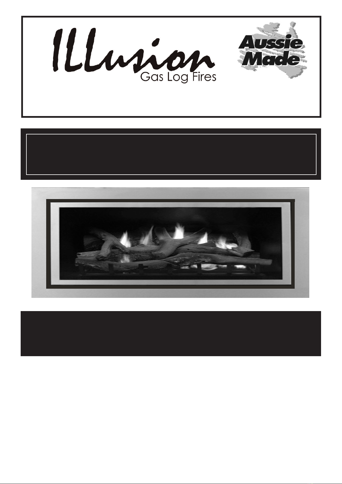
Illusion Aussie Made LCSII-LUMINAR Series User manual
1
LCSII-LUMINAR SERIES OCT 2015
Your new ILLusion LUMINAR Series Gas Log Fire was designed and manufactured in Australia.
THE LUMINAR RANGE CAN BE INSTALLED IN SUITABLY CONSTRUCTED TIMBER OR METAL
ENCLOSURES OR EXISTING FIREPLACES AS PER THE MANUFACTURERS INSTRUCTIONS. PLEASE
READ AND UNDERSTAND THE INSTALLATION INSTRUCTIONS BEFORE COMMENCING TO INSTALL
These appliances have been tested and approved in accordance with Australian Standards
for installation and operation as described in this manual and have been Certied by IAPMO OCEANA
WARNING:
All Illusion Gas Log Appliances MUST be installed and serviced by an authorised technician.
Unauthorised installation, service or maintenance may cause a hazardous situation.
OWNERS INSTRUCTION & INSTALLATION MANUAL. PLEASE KEEP FOR FUTURE REFERENCE
HEAD OFFICE 145 SOUTH GIPPSLAND HWY DANDENONG STH. VICTORIA AUSTRALIA 3175
PH: 03 9793 7520 FAX: 03 9793 7530 Email sales@illusionres.com.au
www.illusionres.com.au
MODELS: LCSII - LUMINAR SERIES
THIS GAS LOG FIRE IS SUPPLIED WITH A PRIMARY GUARD FOR YOUR PROTECTION.
THE PRIMARY GUARD MUST BE FITTED WHEN THE UNIT IS OPERATING
THE GLASS FRONT OF THE APPLIANCE IS EXTREMELY HOT WHEN THE UNIT IS RUNNING AND
SEVERE BURNS MAY RESULT THROUGH CONTACT WITH THE GLASS IF THE PRIMARY GUARD IS
NOT FITTED. ADDITIONALLY A SECONDARY FIRE SCREEN MAY BE APPROPRIATE WHEN SMALL
CHILDREN OR THE INFIRM ARE IN THE VICINITY OF THE APPLIANCE.

2
LCSII-LUMINAR SERIES OCT 2015
Australian Made Gas Log Fires
Your new ILLusion Luminar Series Gas Log Fireplace is the latest from Australias best loved Gas Log
Fireplace mnanufacturer. The combination of innovative features designed for Australian conditions and a genuine
open re appearance with the safety of a full ceramic glass front ensures this appliance is the Ultimate in Gas Log
Fireplaces.
The ILLusion Luminar Gas Log Fireplace provides you with continuous warmth, and the traditional charm of an open
re, without the hard work generally associated with a wood fuelled appliance.
Safe and economical, you can rest easy knowing that every ILLusion Gas Log Fireplace has been fully tested and
approved to Australian Standards.
NOTE: ILLUSION Luminar SERIES GAS LOG FIREPLACES ARE DESIGNED TO BE INSTALLED IN A
SUITABLY CONSTRUCTED WALL, FIREPLACE FACADE OR CHIMNEY. THESE UNITS MUST ONLY
BE INSTALLED BY AN AUTHORISED INSTALLER IN ACCORDANCE WITH AUSTRALIAN STANDARDS.
TABLE OF CONTENTS
PAGE DESCRIPTION
3 DIMENSIONS ALL LUMINAR MODELS
4. INSTALLATION INSTRUCTIONS
5. LUMINAR INBUILT INSTALLATION
6. LUMINAR STAND ALONE INSTALLATION
7. SPECIFICATIONS / CONNECTIONS / ABNORMAL OPERATION
8. LIGHTING INSTRUCTIONS
9. CONTROL IDENTIFICATION-PRIMARY GUARD AND DOOR REMOVAL
10. INSTALLER NOTES & SAFETY INFORMATION
11. FITTING THE LOGS
12. FITTING THE LOGS
13. FITTING THE PEBBLES
14 FITTING THE PEBBLES
15 PRESSURE TESTING
16. MAINTENANCE AND SERVICING
17. INSTALLATION OF FASCIAS AND TRIMS
18 THERMOSTATICALLY CONTROLLED FAN
19. REMOTE CONTROLLER
20. TROUBLESHOOTING
21. ILLUSION CONTACT DETAILS

3
LCSII-LUMINAR SERIES OCT 2015
Australian Made Gas Log Fires
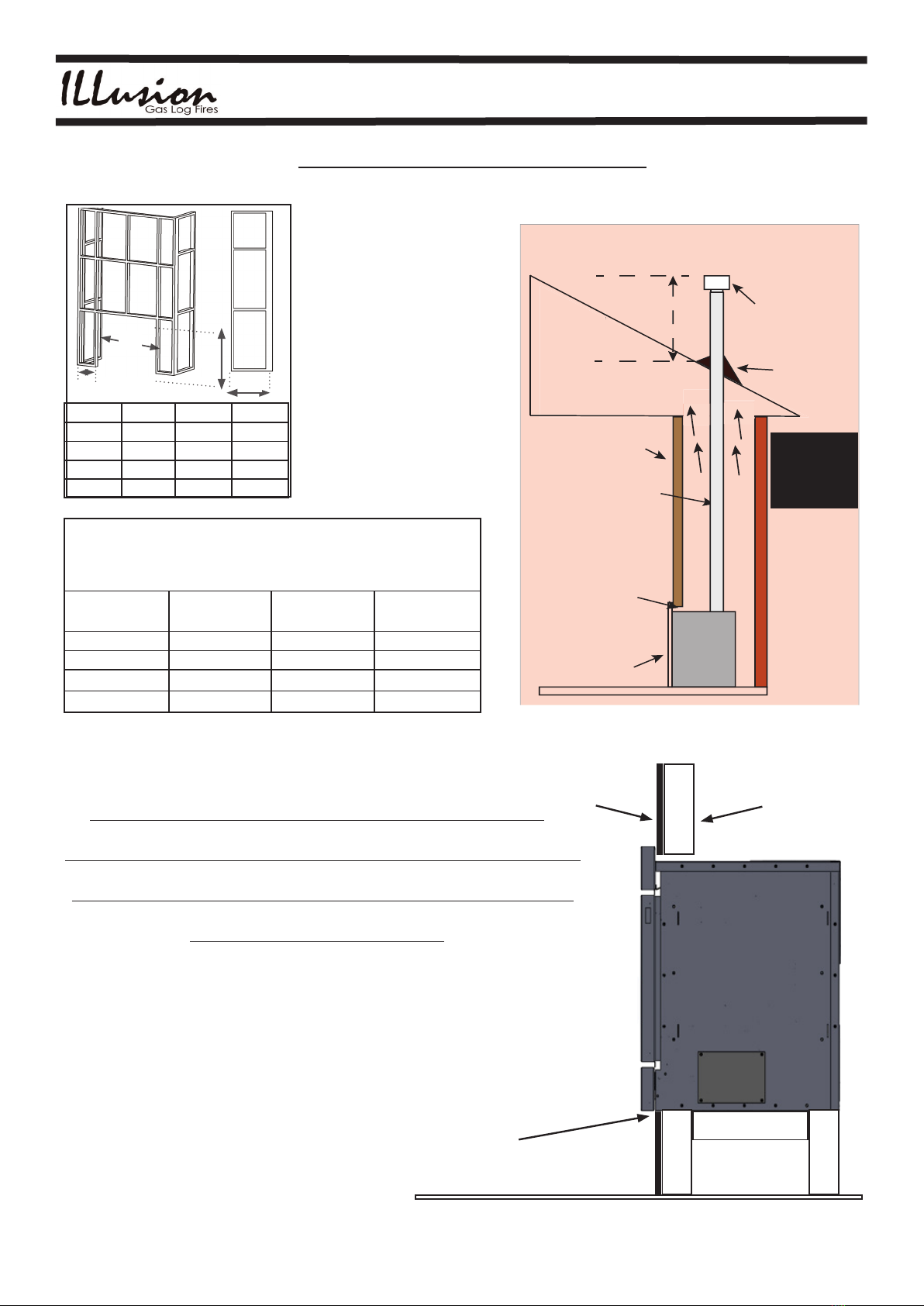
DIMENSIONS Luminar Inbuilt ALL DIMENSIONS IN MILLIMETRES
External dimensions for all Luminar Inbuilt Gas Log Fires (All dimensions in millimeters)
Luminar MODEL Width(A) Height (B) Height of Rear
Casing (C)
Depth Of Rear
Casing (D)
Width Of Rear
Casing (E)
Depth to Flue Centre
from Fascia Front -
Vertical Flue model (F)
LC-1000i 845 (Fascia) 525 (Fascia) 490 415 685 320
LC-2000i 945 (Fascia) 565 (Fascia) 535 415 785 320
LC-3000i 1045 (Fascia) 610 (Fascia) 575 415 885 320
LC-4000i 1410 (Fascia) 595 (Fascia) 570 415 1250 320
DIMENSIONS Luminar Stand Alone
External dimensions for all Luminar STAND ALONE Gas Log Fires (All dimensions in millimeters)
Luminar MODEL Width(A) Height (B) Height of Rear
Casing (C)
Depth (D)
LC-1000F Width 845
Height 725 (Inc.Pedestal)
n/a 470 (Overall)
LC-2000F Width 945
Height 745 (Inc. Pedestal)
n/a 470 (Overall)
LC-3000F Width1045
Height 785 (Inc. Pedestal)
n/a 470 (Overall)
(A)
(A)
(B)
(C)
(E)
(F)
(A)
(B)
(C)
(D)
IMPORTANT
The installation of any ILLusion Gas Log Appliance must be performed only by authorised personnel and in accordance with the
manufacturer’s installation instructions, local gas tting regulations, municipal building codes, electrical wiring regulations, AS
5601 Gas Installations and any other statutory regulations.Please read these instructions carefully before proceeding.
PRIOR TO INSTALLATION
It is highly recommended that the installation of any ILLusion Gas Log appliance is planned on paper before installation begins.
This will ensure correct performance of the unit and eliminate potential problems.
Your ILLusion sales representative can advise on the best position to maximize the performance of the appliance.
In most cases, an Authorised ILLusion Installer can be arranged to install the unit, however if this is not possible, a suitably
qualied gas tter must be used. These appliances are not designed to be installed by the homeowner.

4
LCSII-LUMINAR SERIES OCT 2015
Australian Made Gas Log Fires
INSTALLATION INSTRUCTIONS
NOTE THAT THIS GAS APPLIANCE MAY ONLY BE INSTALLED BY AN AUTHORISED
PERSON. CONTACT YOUR DEALER TO ARRANGE INSTALLATION.
INSTALLATION PROCEDURE
INSTALLERS CHECKLIST
1. IMPORTANT: BEFORE COMMENCING THE INSTALLATION, ESTABLISH THE OPTIMAL POSITION
FOR THE APPLIANCE WITH REGARD TO:
CLEARANCE FROM COMBUSTIBLE MATERIALS, POSSIBLE OBSTRUCTIONS WITHIN THE ROOF CAVITY
OR CHIMNEY, ACCESSIBILITY FOR FUTURE SERVICING, ETC:
2. APPLIANCE & COMPONENT INSPECTION
Remove the APPLIANCE CARTON and other packaging. Inspect the appliance thoroughly to ensure it has not
been damaged in transit. Set aside the carton containing the log kit. Check to see that the correct kit is supplied.
Open the FLUE KIT carton and check to see all components are supplied including the ue lengths, outer casing,
mounting brackets & gas cowl. Ensure that the correct ue kit for your model has been supplied.
IMPORTANT:
THE MINIMUM FLUE DIMENSIONS REQUIRED FOR THESE UNITS ARE AS FOLLOWS:
MINIMUM DIAMETER OF ACTIVE FLUE ALL MODELS IS 100MM. A STAINLESS STEEL
FLUE PIPE IS USED FOR THE FIRST LENGTH OF ACTIVE FLUE PIPE. GALVANISED FLUE
PIPE IS USED FOR SUBSEQUENT LENGTHS . THE MINIMUM OVERALL HEIGHT OF THE
FLUE SYSTEM WHEN INSTALLED IS 2.7 METRES (VERTICAL FLUE EXIT MODELS) (NOT
INCLUDING GAS COWL ASSEMBLY) THE RECOMMENDED MAXIMUM FLUE HEIGHT IS
4.5 METRES (VERTICAL FLUE EXIT MODELS)
ONLY THE APPROVED GAS COWL ASSEMBLY AS TESTED WITH THE APPLIANCE MAY
BE USED WITH THESE APPLIANCES.
NOTE: These appliances are designed to be installed with a vertical ue for maximum
performance. FLASHING (IF REQUIRED) IS NOT INCLUDED AND MUST BE SUPPLIED BY THE
INSTALLER.
3. POSITION THE HEATER.
(ASSUMES THAT AREA IS READY FOR THE UNIT.)
Place the heater in the required position as determined in section 1 (above).
Determine where the gas supply will be accessed.
Mark the gas pipe entry point on the wall or oor, (See DIMENSIONS page 3) and cut the hole(s).
NOTE: It is highly recommended that a gas supply shut off valve be tted to the gas inlet pipe outside the building
in an easily accessed position to enable the gas to be shut off in an emergency. This also makes it possible to keep
the gas supply connected to the rest of the home whilst tting the pipe to the back of the heater prior to connecting
gas to the appliance.
5
LCSII-LUMINAR SERIES OCT 2015
Australian Made Gas Log Fires
All dimensions for the Illusion Luminar series of Gas Log Fires are correct at the time of printing. It is always advisable to
check dimensions and clearances with your Illusion dealer before commencing installation thus avoiding potential
problems during the installation.
Plaster cut out sizes. (Suits Standard fascia)
IMPORTANT: If an inbuilt unit is installed at oor level, or up to 600mm
from the underside of the appliance door, a hearth should be used for a
distance of 400mm in front of the appliance. The appliance should be
installed 600mm or more from the oor if no hearth is used.
Luminar Model PLASTER CUTOUT
HEIGHT (MUST BE
ACCURATE)
PLASTER CUTOUT
WIDTH
MIN. DEPTH OF
FRAMEOUT
1000 510mm 705mm 450mm
2000 555mm 805mm 450mm
3000 595mm 905mm 450mm
4000 590mm 1270mm 450mm
The Illusion Luminar Gas Log Fires
have been designed for simple
installation through an existing
wall (external or internal). They
can also be installed into a
purpose built enclosure or an
existing suitably large chimney.
The diagram at left shows an
example of an enclosure which
would attach to an existing
internal wall. The enclosure
can be plastered or faced
with a variety of materials
including tiles or stone and other
decorative masonary products.
The enclosure should be a
minimum of 300mm wider than
the hole cut out. Check with
your dealer for more detailed
information.
B1
C1
Minimum
Width of
Frameout
A1
Model A1 B1 C1
1000 765mm 540mm 440mm
2000 865mm 585mm 440mm
3000 965mm 635mm 440mm
4000 1330mm 620mm 440mm
Horizontal
or Vertical
Flue
Luminar
Gas Log
Fire
Stud Wall
Flue Pipe
100mm
(4”)
Active &
152mm
(6”)
Outer
Approved
Vertical
Flue Cowl
Flashing
(Supplied
by
Installer)
Minimum
500mm
from flue cowl
exit to roof
penetration
EXAMPLE VERTICAL AND HORIZONTAL
INSTALL VERSIONS
Appliance
Fascia
ALL LUMINAR GAS
LOG FIRES MUST BE
INSTALLED IN
ACCORDANCE WITH
AS-NZS 5601
CURRENT EDITION
Minimum
distance
from flue
case outer
pipe to
combustible
materials is
10mm
Minimum distance from top
of unit to any combustible
framing is 50mm.
Minimum distance from rear
of unit to any combustible
material is 10mm.
Minimum distance from side
of unit to any combustible
material is 50mm
p
pe
Clear path to vent
air to ceiling
INBUILT CLEARANCES
LUMINAR INBUILT INSTALLATION
IMPORTANT!
The plaster cut out must be
straight and accurate, especially
at the bottom. There is no overlap
of the fascia at the bottom so the
bottom plaster edge must be cut
carefully. It is recommended that
a plaster trim strip be tted.
INSTALLER INFORMATION
READ THIS BEFORE CUTTING
ANY HOLES IN PLASTER OR
OTHER WALLS
FASCIA
PLASTER
LUMINAR
INBUILT
WALL STUD
300mm
min

6
LCSII-LUMINAR SERIES OCT 2015
Australian Made Gas Log Fires
The Illusion Luminar STAND ALONE Gas Log Fires have been designed
for simple installation with the approved balanced ue provided. The
miniumum
ue height is 2.7m, the maximum recommended ue height is 4.5m Most
installations will use the standard ue height of 3.6m
Illusion Luminar gas log res must only be installed by an authorised
gastter.
Stand Alone Clearances
The diagrams below show examples of stand alone Luminar installs
with respect to clearances from combustible materials ie: walls. The
minimum distance from the REAR of all Luminar Stand Alone models
to any combustible surface is 10mm. The minimum distance from the
SIDES of all Luminar Stand Alone models is 100mm.
The minimum distance from the REAR CORNERS to combustible walls
in a 45 degree corner install is 10mm.
(A)
(A)
(B)
(C)
Example Corner Install (ALL LUMINAR Stand Alone)
50mm REAR WALL (ALL LUMINAR Stand Alone)
50mm
50mm
(Min.)
50mm
(Min.)
Vertical
Flue
LUMINAR
Gas Log
Fire
Flue Pipe
100mm
(4”)
Active &
152mm
(6”)
Outer
Approved
Vertical
Flue Cowl
Flashing
(Supplied
by
Installer)
Minimum
500mm
from flue cowl
exit to roof
penetration
TYPICAL FLUE INSTALLATION
Appliance
Fascia
ALL LUMINAR GAS
LOG FIRES MUST BE
INSTALLED IN
ACCORDANCE WITH
AS-NZS 5601
CURRENT EDITION
Minimum
distance
from flue
case outer
pipe to
combustible
materials is
10mm
Minimum
distance
from top of
unit to any
combustible
framing is
50mm
Minimum
distance
from
combustible
rear wall to
the back of
the unit is
10mm
LUMINAR STAND ALONE INSTALLATION
All dimensions for the Illusion Luminar series of Gas Log Fires are correct at the time of printing. It is always
advisable to check dimensions and clearances with your Illusion dealer before commencing installation
thus avoiding potential problems during the installation.
IMPORTANT NOTE TO INSTALLER
Caution: Check the appliance before leaving.
Check that logs or pebbles are correctly located. Incorrect location of logs or pebbles
will affect combustion and may cause sooting.
Check the gas pressure.
Light the appliance and check for ame abnormalities on both high and low ame
settings. Flames should not lift off the burner ports. Allow the unit about 5 minutes to
warm up then if the ames are lifting from the burner ports it may be necessary to
adjust the gas pressure on the gas valve.
7
LCSII-LUMINAR SERIES OCT 2015
Australian Made Gas Log Fires
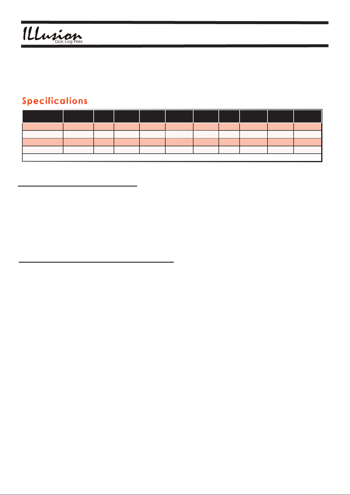
Specifications
MODEL GAS TYPE MJH INJECTOR
SIZE
PRESSURE
HIGH
PRESSURE
LOW
GAS TYPE MJH INJECTOR
SIZE
PRESSURE
HIGH
PRESSURE
LOW
Luminar LC-1000 NAT 20 2.1 .85 .39 LPG 16 1.3 1.8 1.23
Luminar LC-2000 NAT 26 2.35 .85 .40 LPG 25 1.6 1.6 1.10
Luminar LC-3000 NAT 32 2.6 .90 .47 LPG 30 1.8 1.6 0.65
Luminar LC-4000 NAT 39 3.05 .75 .30 LPG 39 2.0 1.7 0.77
ELECTRICAL COMPONENTS CONFORM TO AS 3100 240V 50HZ 60 WATTS
The dimensions, capacities, ratings etc quoted here are correct at the time of writing but may be subject to change.
Please check with your dealer before commencing any building works or installations of these appliances.
Manufactured by Illusion Australia Pty. Ltd. 145 Sth. Gippsland Hwy Dandenong
Sth. 3175 Victoria Australia
Phone: 613 9793 7520 Fax: 613 9793 7530
NATURAL Gas Connection
The connection is made using gas pipes with Rp1/2 ISO 7 threading. Torque: 25Nm
If, alternatively, anges are used, rst screw the pipes on to the anges and then the
anges to the valve. Recommended torque for the ange xing screws: 3Nm.
It is recommended that an Approved and certied shutoff valve be tted between the incoming gas line and
the appliance to enable the gas supply to the appliance to be shut off independantly from the mains gas
supply.
Caution: Af ter making the connections, check gas tightness.C H ECK AND SET APPROPRIATE GAS PRESSURE
USING ABOVE CHART FOR NATURAL GAS ONLY
THE FOLLOWING INDICATES SITUATIONS OF ABNORMAL OPERATION OF THE APPLIANCE.
WHEN THE APPLIANCE IS OPERATING :
1. The ames appear excessively large and / or sooting occurs on the logs.
2. You can smell gas.
3. The ame pattern is inconsistent and appears to be lifting off the burner.
4. You can smell the products of the ue within the room in which the appliance is installed. (May be an
indication of a blocked ue)
If any of the above situations occur, turn the appliance off, and contact your supplier or installer
immediately. If you can smell gas, turn the gas off at the mains and call the appropriate authority.
Always call from outside the building from a neighbors, or with a mobile phone.
ABNORMAL OPERATION
LIQUID PROPANE Gas Connection
The connection is made using gas pipes with Rp1/2 ISO 7 threading. Torque: 25Nm
If, alternatively, anges are used, rst screw the pipes on to the anges and then the
anges to the valve. Recommended torque for the ange xing screws: 3Nm.
It is recommended that an Approved and Certied shutoff valve be tted between the incoming gas line
and the appliance to enable the gas supply to the appliance to be shut off independantly from the mains gas
supply.
Caution: After making the connections, check gas tightness. CHECK GAS PRESSURE USING ABOVE CHART
FOR LIQUID PROPANE GAS ONLY.
8
LCSII-LUMINAR SERIES OCT 2015
Australian Made Gas Log Fires
LIGHTING INSTRUCTIONS
CAUTION: HOT WHILE OPERATING.
DO NOT TOUCH. KEEP CLOTHING, CHILDREN AND FURNITURE AWAY.
KEEP BURNER AND CONTROL COMPARTMENT CLEAN AND FREE FROM LINT, DUST ETC.
This appliance shall be installed only by authorised personnel and in accordance with the manufacturer’s installation
instructions, local gas tting regulations, municipal building codes, electrical wiring regulations, AS 5601/AG 601 - Gas
Installations and any other statutory regulations.NEVER ATTEMPT TO LIGHT THE APPLIANCE IF YOU CAN SMELL
GAS. IF IN DOUBT, CONTACT YOUR GAS SUPPLIER, APPLIANCE INSTALLER AND OR ILLusion SERVICE
DEPARTMENT FROM A NEIGHBOURS HOME. IF YOU CAN SMELL GAS, DO NOT USE MOBILE PHONES OR
ANY ELECTRICAL APPLIANCE, OR ELECTRIC SWITCH IN THE BUILDING.
This appliance incorporates a live fuel effect, which is designed to operate with luminous ames and may exhibit slight
carbon deposition.
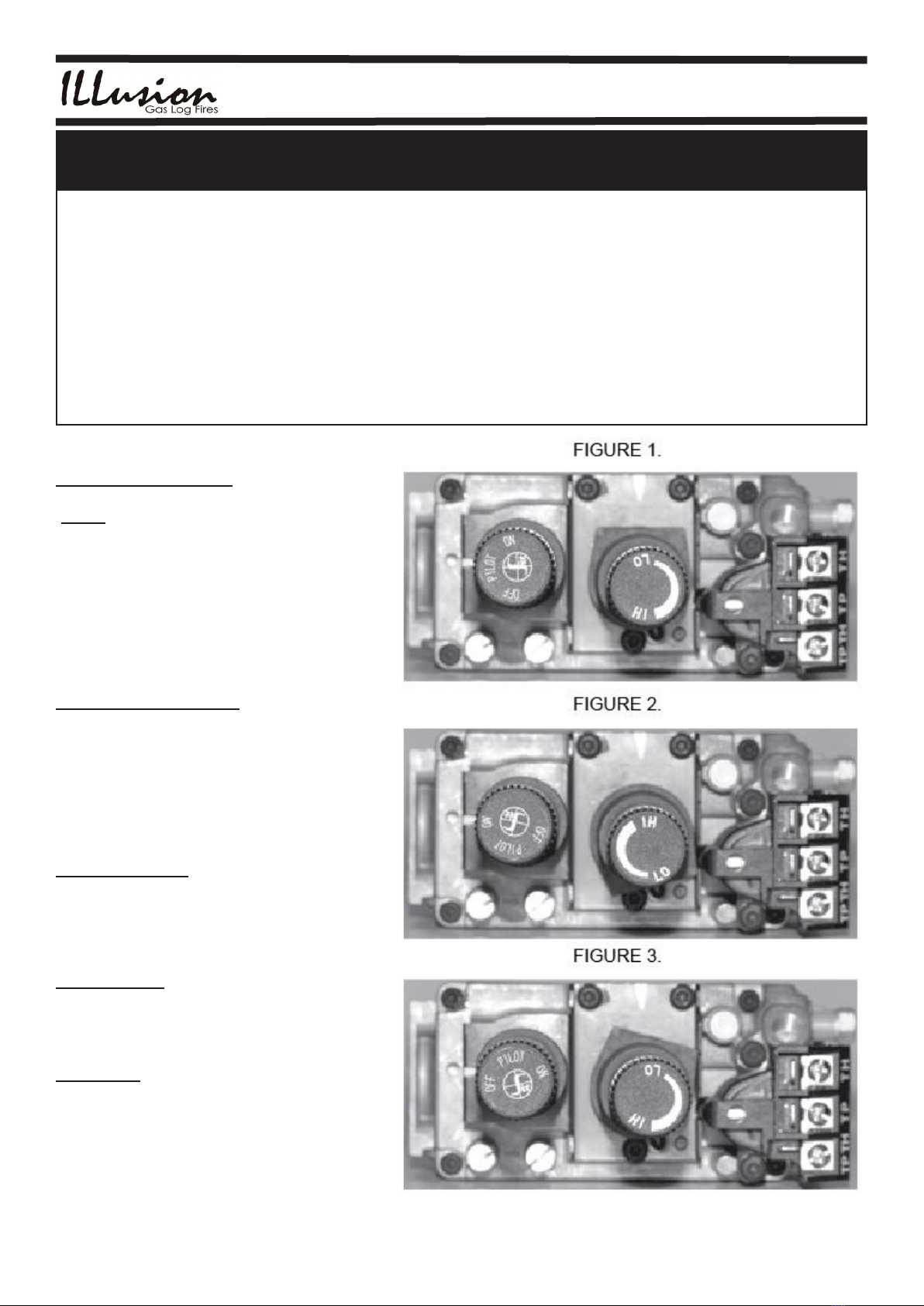
PILOT FLAME IGNITION
Depress and turn the control knob to the
“PILOT” position.
Depress the button and ignite the pilot ame
(by pressing the red igniter button) while
keeping the knob fully depressed for a
few seconds. (Fig. 1).
Release the knob slowly and check that the
pilot ame stays lit. If it goes out, repeat the
ignition operation.
MAIN BURNER IGNITION
Turn the HI-LO control knob to HI.
Depress and turn the control knob to the
“ON” position. (Fig. 2)
When the automatic solenoid valve is
energized, gas passage to the main burner
is opened.
PILOT POSITION
To keep the main burner closed and the pilot
ame lit, depress and turn the control knob
to the “PILOT” position.
TURNING OFF.
Depress and turning the control knob to the
“OFF” position Fig. 3)
CAUTION:
The restart interlock device prevents ignition
of the appliance until the ame failure has
stopped gas ow. At the end of this period
it is possible to carry out the re-ignition
operation.

9
LCSII-LUMINAR SERIES OCT 2015
Australian Made Gas Log Fires
PRESS
TO
IGNITE
DO NOT OPERATE THIS APPLIANCE BEFORE
READING THE INSTRUCTION BOOKLET
DO NOT PLACE ARTICLES ON OR AGAINST
THIS APPLIANCE
DO NOT STORE CHEMICALS OR FLAMMABLE
MATERIALS OR SPRAY AEROSOLS NEAR
THIS APPLIANCE
DO NOT OPERATE WITH PANELS, COVERS OR
GUARDS REMOVED FROM THIS APPLIANCE
CERTIFICATION NO.
GMK10350
ELECTRICAL COMPONENTS
CONFORM TO AS 3100
240V 50HZ 60 WATTS
PILOT TEMPERATURE
Fan
Low
Fan
High
To replace batteries in remote receiver,
first remove the 2 screws below & lift off
receiver box cover. Unclip battery box cover
& remove batteries. Replace batteries & re program
remote receiver.
MODEL
1000 - HIGH 1000 - TURNDOWN
GAS TYPE
NOM. HOURLY GAS CONSUMPTION
MANIFOLD PRESSURE
INJECTOR SIZE
NAT NAT
20Mjh 13.5Mjh
.85kPa .39kPa
2.1mm
PRIMARILY A DECORATIVE APPLIANCE, NOT CERTIFIED AS A SPACE HEATER
1000 Series Gas Log Fire
Luminar
AS-4558
PART # IL-LUM-1000
C
M
Y
CM
MY
CY
CMY
K
LUMINAR 1000 LABEL.pdf 1 9/11/2015 9:39:12 AM
CONTROL IDENTIFICATION
GAS OFF
PILOT ON
& MAIN GAS ON
FAN CONTROL
SWITCH
PUSH BUTTON
PIEZO IGNITER
REMOTE
CONTROL SWITCH
FLAME CONTROL
HI - LO
SPECIFICATIONS
NOTE: LPG VERSIONS SHOW
SPECIFICATIONS FOR LPG APPLIANCES
PRIMARY GUARD
THIS GAS LOG FIRE IS SUPPLIED WITH A PRIMARY GUARD FOR YOUR PROTECTION.
THE PRIMARY GUARD MUST BE FITTED WHEN THE UNIT IS OPERATING
THE GLASS FRONT OF THE APPLIANCE IS EXTREMELY HOT WHEN THE UNIT IS RUNNING AND
SEVERE BURNS MAY RESULT THROUGH CONTACT WITH THE GLASS IF THE PRIMARY GUARD
IS NOT FITTED. ADDITIONALLY A SECONDARY FIRE SCREEN MAY BE APPROPRIATE WHEN
SMALL CHILDREN OR THE INFIRM ARE IN THE VICINITY OF THE APPLIANCE.
REMOVAL FOR SERVICING.
To remove the primary guard and door trim or to access the Main Door for removal, simply lift the trim
guard upwards than out towards you. It has 4 tabs which lock into 4 slots. To replace it, t the bottom tabs
into the slots rst, then the top tabs into the top slots and push down to lock into place. (HINT Make sure
the door Allen head bolts above and below the door are tight before trying to remove or replace the door
trim guard. This will make it much easier to to remove or re-t)
DOOR REMOVAL
To remove the Main door to access the gas components for servicing, rst remove the door trim guard as
above.
Make sure the door Allen head bolts above and below the door are tight before trying to remove the door
trim. Then lift the door guard trim at the base out towards youas explained above.
Now remove the four Allen head bolts bolts that secure the door, Remove the door and set aside.
SIZE IS 450 X 70mm PART #IL-LUM-COMMON DOOR LABEL
FANROCKER SWITCH
FASCIA ROCKER
SWITCH
A
HIGH
LOW
BLACKTO
HIGH
BROWNFROM
LOOMTO LOW
BLACK
BROWN
NOTE:WHITE WIRE NOT USED
WIRING DIAGRAM LUMINAR WITH REMOTE
BROWNFROM POWER
LEAD TO ACTIVE “A”
OVERTEMPERATURE
CUTOUTSWITCH
BROWN
CONNECTTO TPTH AND TH
ONTHE GAS VALVE
LEARN
FMRECEIVER BOX
FANROCKER SWITCH
A
HIGH
LOW
BLACKTO
HIGH
BROWNFROM
LOOMTO LOW
BLACK
BROWN
NOTE:WHITE WIRE NOT USED
WIRING DIAGRAM LUMINAR NO REMOTE
BROWNFROM POWER
LEAD TO ACTIVE “A”
BROWN
FASCIA ROCKER
SWITCH
OVERTEMPERATURE
CUTOUTSWITCH
CONNECTTO
TPTHAND TH ON
THEGAS VALVE
C
M
Y
CM
MY
CY
CMY
K
LUMINAR LIGHTING INSTRUCTIONS LABEL.pdf 1 29/10/2015 12:28:37 PM
LIGHTING INSTRUCTIONS WIRING DIAGRAM & WARNING LABELS
MODEL
1000 - HIGH 1000 - TURNDOWN
GAS TYPE
NOM. HOURLY GAS CONSUMPTION
MANIFOLD PRESSURE
INJECTOR SIZE
LPGL PG
16Mjh 10.9Mjh
1.80kPa .77kPa
1.3mm

10
LCSII-LUMINAR SERIES OCT 2015
Australian Made Gas Log Fires
1. These appliances must be installed in accordance with the regulations, municipal building codes and
AS 5601 ‘GAS INSTALLATIONS’
2. Only an Authorised person should install the appliance.
3. This appliance should be inspected prior to installation and the dealer contacted if any problems arise.
4. This appliance must be installed with an approved ue system, which terminates outside the building.
A ue system must never terminate within the roof cavity.
5. The unit should be checked periodically for lint. The fan area especially is prone to lint build up during
normal operation. Keep the area around the appliance clean and free from lint.
6. Only persons familiar with the operation of the unit should use the heater.
7. Do not modify or adjust the heater. Always contact your ILLusion dealer if any problems arise.
8. Annual service by an Authorised service person will ensure trouble free operation for many years.
9. This Gas heater is not designed to burn solid fuels. NEVER use paper, wood or any other fuel in this
appliance.
10. Keep the immediate area around the heater free from any combustible materials: i.e.: aerosols, or other
ammables.
11. If you smell gas whilst the unit is operating, immediately shut down the unit and turn the gas off at the
supply shut off valve, or the main meter. Contact Illusion or your local gastter.
DO NOT ATTEMPT ANY REPAIRS ON THE HEATER YOURSELF. ONLY AN AUTHORISED GASFITTER MAY REPAIR OR
ADJUST THE HEATER ACCORDING TO THE MANUFACTURERS INSTRUCTIONS.
PAINT CURING
SOME SURFACES OF YOUR ILLUSION GAS APPLIANCE HAVE BEEN FINISHED WITH HEAT RESISTANT
PAINT. OTHER SURFACES ARE POWDER COATED. PLEASE NOTE THAT THE INITIAL FIRING OF THE
UNIT MAY PRODUCE SOME SMOKE AND ODOUR AS THE PAINT ON THE FIREBOX CURES. TO ENABLE
CURING, THE UNIT MUST BE RUN ON LOW WITH THE FAN ON LOW FOR APPROX. 3 - 4 HOURS. IT IS
ADVISABLE TO KEEP WINDOWS AND DOORS OPEN DURING THIS PERIOD IF POSSIBLE.
SAFETY INFORMATION
DO NOT PLACE ARTICLES ON OR AGAINST THIS APPLIANCE.
DO NOT USE OR STORE FLAMMABLE MATERIALS NEAR THIS
APPLIANCE.
DO NOT SPRAY AEROSOLS IN THE VICINITY OF THIS APPLIANCE
WHILE IT IS IN OPERATION.
CERTIFIED UNDER AS 4558 - NOT CERTIFIED AS A SPACE
HEATER.

11
LCSII-LUMINAR SERIES OCT 2015
Australian Made Gas Log Fires
WHEN INSTALLING LOGS, ENSURE THAT BURNER HOLES ARE NOT BLOCKED.
Obsructing any of the burner holes may result in poor performance and can cause sooting to occur.
CAUTION: LOGS ARE FRAGILE. PLEASE TAKE CARE WHEN INSTALLING
WARNING: DO NOT USE LOGS OTHER THAN THOSE SUPPLIED BY THE MANUFACTURER
OR A HAZARDOUS SITUATION MAY RESULT.
Fit the logs as shown in the photos below. Always start at the rear, then the middle, then the front. The logs
have holes to correspond with the pins near the burners.
6
1 2 3
4 5
Luminar 1000
1 2 3
4 5
Luminar 2000
Fit the large rear number 1 log rst. Fit the long number 2 log next on
the middle row
Next t either the lhs (number 3) or
rhs (number 4) log to the front. Fit the remaining log over the pins
and the logset is complete!
Empty rebox with door removed
ready to t the logs.
Empty rebox with door removed
ready to t the logs. Fit the rear number 1 log rst. Fit the number 2 log next on the
left hand side middle row
Fit the number 3 log next on the
rhs of the middle row. Now t the number 4 log on the lhs
of the front row Finally, t the number 5 log on the
rhs of the front row to complete
the logset.
FITTING INSTRUCTIONS FOR LOGS
NEVER FIT LOGS OR PEBBLES OTHER THAN THOSE SUPPLIED WITH THE APPLIANCE OR A HAZARDOUS SITUATION
MAY RESULT. BROKEN OR DAMAGED LOGS OR PEBBLES MUST BE REPLACED WITH THE CORRECT PART.
CONTACT YOUR NEAREST ILLUSION DEALER FOR MORE INFORMATION.

12
LCSII-LUMINAR SERIES OCT 2015
Australian Made Gas Log Fires
1 2 3
4 5
Luminar 3000
1 2 3
Luminar 4000
Fit the large rear number 1 log rst. Fit the number 2 log next on the lhs
of the middle row
Next t the number 3 log to the rhs
of the middle row Now t the number 4 log to the lhs
of the front row
Empty rebox with door removed
ready to t the logs.
Empty rebox with door removed
ready to t the logs. Fit the rear number 1 log rst. Fit the number 2 log next on the
rhs rear
6
4 5
Fit the number 3 log next on the lhs
of the middle row. Now t the number 4 log 2nd from
the left on the middle row Finally, t the number 5 log 3rd
from the left on the middle row
FITTING INSTRUCTIONS FOR LOGS (CONT.)
6
Finally, t the number 5 log on the
rhs of the front row to complete
the logset.
9
78
Fit the number 6 log next on the lhs
of the front row. Now t the number 7 log in the
middle of the front row Finally, t the number 8 log on the
rhs of the front row to complete
the logset.
13
LCSII-LUMINAR SERIES OCT 2015
Australian Made Gas Log Fires
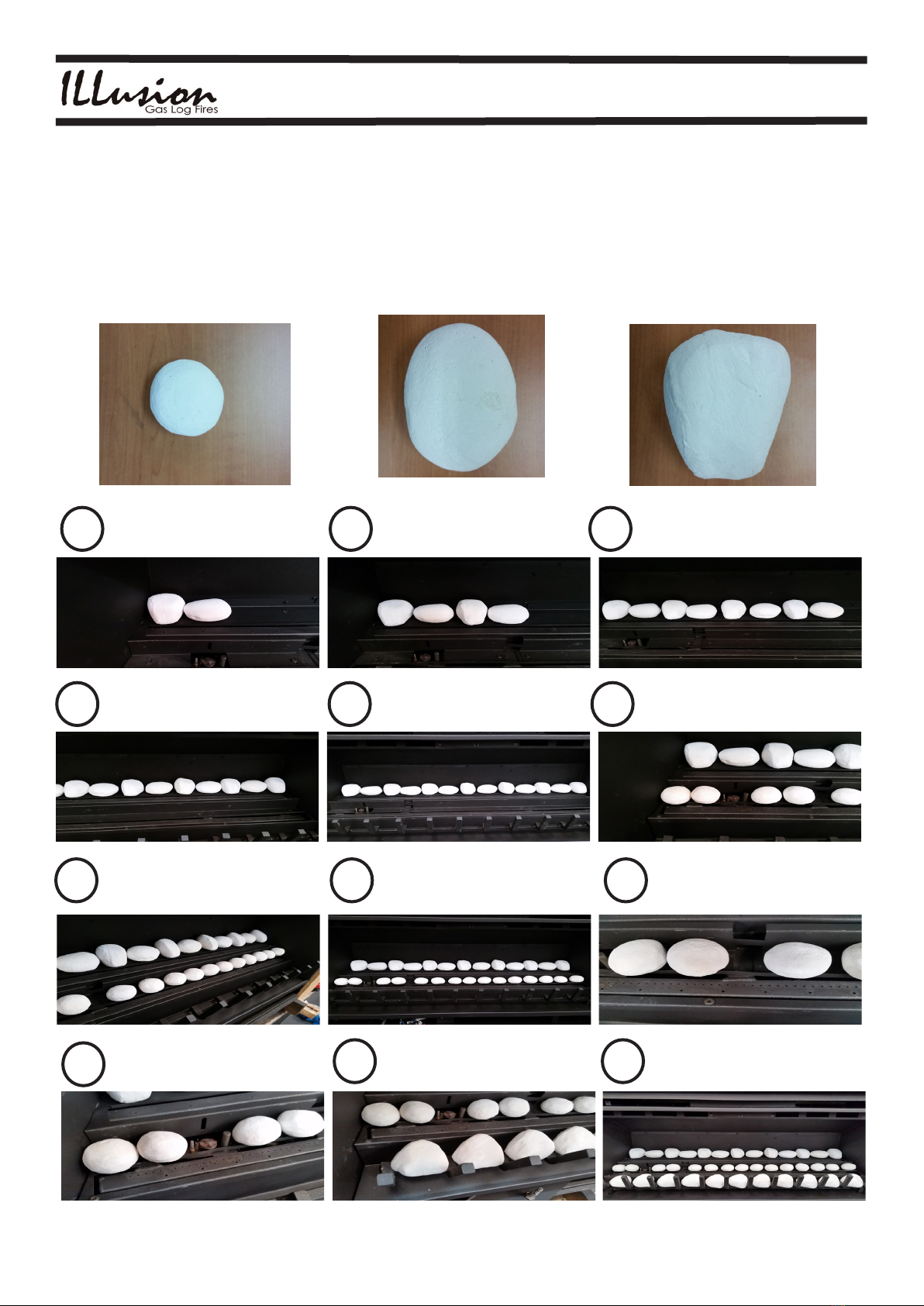
FITTING THE PEBBLES - LUMINAR
1 2 3
4 5 6
789
11
10
COMPLETED PEBBLES
12
Start at the back row left, tting one
of the large irregular pebbles rst,
then one large oval shaped pebble,
altenating as you go.
Make sure to keep the pebbles
clear of the burner ports and
continue alternating between the
irregular and oval pebbles.
The completed back row should
contain 7 of the irregular shaped
pebbles and 6 of the oval pebbles.
Don’t worry too much about
spacing between the pebbles yet.
They can be adjusted once all of
the pebbles have been tted.
Check as you go to ensure the
burner ports are not obstructed by
the pebbles.
The middle row consists of the
smaller oval pebbles. Fit 2 from the
left side before the igniter, then 2
after the igniter as shown below.
Continue tting the small oval
pebbles across the middle row.
The completed middle row (below)
contains 15 small oval pebbles.
Check that the ignition crossover
point (See below) and burner ports
are not obstructed.
Adjust the spacing of the small
pebbles in the middle row until
they are relatively evenly spaced.
Keep the ignition area clear.
Start the bottom row, tting the
large irregular pebbles between
the bars on the grate.
Continue tting the large irregular
pebbles. The completed bottom
row contains 11of the large
irregular pebbles.
There a 3 types of Pebbles supplied, SMALL ROUND, LARGE OVAL, LARGE
IRREGULAR. (See Images)
WARNING: DO NOT USE PEBBLES OTHER THAN THOSE SUPPLIED BY THE
MANUFACTURER OR A HAZARDOUS SITUATION MAY RESULT. WHEN INSTALLING
PEBBLES, ENSURE THAT THE BURNER HOLES ARE NOT OBSTRUCTED.
Obstructing any of the burner holes may result in poor performance.
SMALL
ROUND LARGE
OVAL
LARGE
IRREGULAR

14
LCSII-LUMINAR SERIES OCT 2015
Australian Made Gas Log Fires
S.I.T GAS VALVE: MODEL 820 NOVA mV
IMPORTANT: IF THE APPLIANCE CANNOT BE ADJUSTED TO OPERATE CORRECTLY, CONTACT YOUR
SUPPLIER AND DO NOT OPERATE THE APPLIANCE UNTIL THE PROBLEM IS RECTIFIED.
PRESSURE TESTING:
ENSURE THE HEATER IS ISOLATED FROM THE GAS SUPPLY BY CLOSING THE MANUAL SHUTOFF VALVE DURING
ANY PRESSURE TESTING.
THE GAS VALVE REGULATOR CONTROLS MANIFOLD PRESSURE AND SHOULD BE CHECKED AT THE PRESSURE
TEST POINT. (SEE BELOW)
NOTE: BOTH INLET AND MANIFOLD PRESSURES SHOULD BE CHECKED USING THE VALVE PRESSURE PORTS ON
THE GAS VALVE.
PROCEDURE: TURN VALVE TO “OFF” POSITION.
LOOSEN INLET PRESSURE POINT (5)
ATTACH MANOMETER TO INLET PRESSURE POINT (5)
LIGHT THE PILOT (SEE LIGHTING INSTRUCTIONS)
TURN VALVE TO “ON”
THE PRESSURE SETTING MUST BE WITHIN THE LIMITS SPECIFIED ON THE
COMPLIANCE PLATE LOCATED ON THE INSIDE OF THE CONTROL DOOR.
1. GAS COCK KNOB
2. HIGH LOW ADJUSTMENT
3. PILOT BURNER ADJUSTMENT
4. THERMOCOUPLE CONNECTION POINT
5. OUTLET PRESSURE POINT
6. INLET PRESSURE POINT
PRESSURE TESTING
7. PILOT OUTLET
8. MAIN GAS OUTLET
9. MAIN GAS INLET
10. THERMO ELECTRIC SWITCH

15
LCSII-LUMINAR SERIES OCT 2015
Australian Made Gas Log Fires
MAINTENANCE
ANNUAL SERVICE SHOULD BE PERFORMED ONLY BY AN AUTHORISED
ILLusion INSTALLER OR GAS FITTER.
1) Clean the burner and control compartment of lint and house dust by brushing and
Vacuuming at least once a year. When cleaning the logs, use a soft clean brush as
the logs are fragile and easily damaged.
During the annual service the burner should be inspected and cleaned.
2) When unit is cold, wipe surfaces with a damp cloth. Do not use abrasive cleaners.
Parts of the appliance are painted with a heat resistant paint. To retouch, refer to
manufacturer.
3) Check the ames periodically. The ames should be steady and not lifting off the burner
holes. The logs should not have any sooting (black areas). If there is a problem, call an
authorised gas tter or your local dealer.
4) The appliance and ue system must be inspected by an authorised person before using and
at least annually. The burner should be inspected and cleaned if required.
5) Keep the area near the appliance clear and free from combustible materials, gasoline
aerosols, and other ammable vapours and liquids
Replacing Logs
The unit should never be used if the logs, coals or rocks are broken. Always turn the gas valve off before
servicing and allow the unit to cool before handling any parts. Remove logs carefully.
Any parts should only be replaced by an Authorised person.
Note: Improper positioning of logs/coals/rocks may create soot build up and carbon monoxide, which will
affect appliance performance. Improper or altered positioning may void your warranty.
FAN ROCKER SWITCH
FASCIA ROCKER
SWITCH
A
HIGH
LOW
BLACK TO
HIGH
BROWN FROM
LOOM TO LOW
BLACK
BROWN
NOTE: WHITE WIRE NOT USED
WIRING DIAGRAM LUMINAR WITH REMOTE
BROWN FROM POWER
LEAD TO ACTIVE “A”
OVER TEMPERATURE
CUTOUT SWITCH
BROWN
CONNECT TO TPTH AND TH
ON THE GAS VALVE
LEARN
FM RECEIVER BOX
FAN ROCKER SWITCH
A
HIGH
LOW
BLACK TO
HIGH
BROWN FROM
LOOM TO LOW
BLACK
BROWN
NOTE: WHITE WIRE NOT USED
WIRING DIAGRAM LUMINAR NO REMOTE
BROWN FROM POWER
LEAD TO ACTIVE “A”
BROWN
FASCIA ROCKER
SWITCH
OVER TEMPERATURE
CUTOUT SWITCH
CONNECT TO
TPTH AND TH ON
THE GAS VALVE
WIRING DIAGRAM

16
LCSII-LUMINAR SERIES OCT 2015
Australian Made Gas Log Fires
Your new Gas Log Fire is tted with a THERMOSTATICALLY CONTROLLED fan.
EXPLANATION
What this means is that other than initially setting the fan to the desired position,ie: Low or High, it
will no longer be necessary to turn the fan on or off whilst the unit is operating.
STARTUP
The new thermo switch will automatically turn the fan on when the heater has reached a
predetermined temperature. This will usually be 5 to 10 minutes after the heater is turned on.
It is important that the owner knows that there is nothing wrong with the heater, in fact it is much
more convenient and energy saving method of operating the fan.
SHUT DOWN
It will also shut down the fan 5 to 10 minutes after the heater is turned off, once the rebox has
cooled sufciently.
REMOTE CONTROLLER OPTION
The above features apply even if the unit is tted with a new OPTIONAL remote controller. If
the remote control is used to turn the appliance on, the fan will startup when the unit reaches
temperature (5 to 10 minutes). If the remote controller is used to turn the heater off, the fan will
shut down when the heater has cooled. (5 to 10 minutes). If the remote control is set to turn off the
appliance at a specied time, the fan will continue to operate until the rebox has cooled, again
usually 5 to 10 minutes. The fans speeds can still be adjusted manually (Hi or Low) whilst the unit
is operating.
THERMOSTATICALLY CONTROLLED FAN

17
LCSII-LUMINAR SERIES OCT 2015
Australian Made Gas Log Fires
OPTIONAL PROFLAME GTM REMOTE CONTROL
REFER TO THE PROLAME INSTRUCTION MANUAL SUPPLIED
REMOTE CONTROL-SUPPLY VOLTAGE - 4.5V (3 X 1.5 AAA BATTERIES
RECEIVER SUPPLY VOLTAGE- 6.0V (4 X 1.5V AA BATTERIES)
TURN OFF THE MAIN GAS SUPPLY DURING INSTALLATION OR MAINTENANCE OF THE RECEIVER.
ON/OFF BUTTON
UP/DOWN ARROW KEY
MODE KEY
PRESS THE SET BUTTON TO SET THE
TEMPERATURE
BATTERIES
THIS REMOTE HAND UNIT USES 3 ‘AAA’ BATTERIES THAT CAN BE CHANGED BY REMOVING THE REAR
ACCESS COVER.
THERMOSTAT KEY

18
LCSII-LUMINAR SERIES OCT 2015
Australian Made Gas Log Fires
TROUBLESHOOTING
SYMPTOM. •The pilot ame goes out.
POSSIBLE CAUSE. •First check that the gas is on, usually with another appliance such as a
gas stove.
•The pilot sensor (Thermocouple) may be faulty.
SOLUTION. • Contact your Dealer.
SYMPTOM. •The main burner ame goes out, but the pilot ame stays on
POSSIBLE CAUSE. •If the unit has a remote control, check that temperature setting is appropriate.
•The gas valve sensor (Thermopile) may be faulty.
•***Sometimes, tting of other new appliances such as Instantaneous hot water
systems, (after the heater has been installed) can affect the performance
of the heater, particulary if the mains piping is undersized. In this case it may
be necessary to have the mains piping re-sized. Contact your Dealer if you
suspect this may be the case.
SOLUTION •Turn off the timer function if active. Relight the re. If symptoms
persist contact your Dealer.
SYMPTOM. •The heater turns off after about 30 minutes
POSSIBLE CAUSE. •Check that the timer function is not active
SOLUTION •The gas valve sensor (Thermopile) may be faulty. Contact your Dealer.
SYMPTOM. •The logs have a build up of black soot in some areas.
POSSIBLE CAUSE. •Usually indicates incorrect positioning of logs if the unit has just been installed.
If the unit has been installed for some time, the inspirator may require cleaning.
Contact your Dealer.
SOLUTION •Re-position the logs as per instructions (See Contents)
SYMPTOM. •The unit rattles when the fan is on.
POSSIBLE CAUSE. •Fan may need cleaning. Fan may be unbalanced.
SOLUTION •If more than 12 months old general maintenance may be required,
contact your Dealer
SYMPTOM. •There is a strong odour and some smoke coming from the unit when on.
POSSIBLE CAUSE. •This usually only happens when the unit is lit for the rst time.
SOLUTION •Refer to PAINT CURING . (See Contents)
SYMPTOM. •The unit will not light beyond pilot ame.
POSSIBLE CAUSE. •(A)The pilot, on-off button is not in position.
•(B)The remote control is not switched to ON
•(C)The batteries in the remote control are at.
•(D)The pilot ame is not reaching the thermopile. Gas pressure may be too low
SOLUTION •(A) Make sure the on off button on the unit is turning to HIGH.
•(B) Press the ON button on the remote control
•(C) Replace the batteries in the remote control.
•(D) (See above***)

19
LCSII-LUMINAR SERIES OCT 2015
Australian Made Gas Log Fires

LCSII-LUMINAR SERIES OCT 2015
Australian Made Gas Log Fires
ILLusion- Australian Made Gas Log Fires
Illusion Gas Log Fires Dealer Contact List
DANDENONG – NEW SUPERSTORE
145 South Gippsland Hwy, Dandenong
Phone: (03) 9793 7520
EPPING
Shop 12/560 High St. VIC. 3076
Phone: (03) 8401 4225
BALLARAT
845 Howitt St. Wendouree VIC .3355
Phone: (03) 5338 2586
ADELAIDE
355 Main North Rd. Eneld, SA. 5084
Phone: (08) 8359 8300
GEELONG
320 Melborne Rd. North Geelong, Vic. 3215
Phone: 1300 966 343
Call our Head Ofce on (03) 9793 7520
Faxes should be sent to (03) 9793 6816
Manufactured by
Illusion Australia Pty Ltd
Head Ofce and Showroom
145 Sth. Gippsland Hwy. Dandenong Sth. Victoria 3175 Australia
Telephone: +61 3 9793 7520 Fax: +61 3 9793 6816
email: service@Illusionres.com.au
www.Illusionres.com.au
Illusion Australia Pty Ltd reserves the right to alter specications contained in this publication.
Illusion Australia Pty. Ltd. admits no responsibility for printing errors or omissions within this publication.
Copyright© Illusion Australia Pty. Ltd. 2015
HOBART
88 Grove Rd. Glenorchy, Tas. 7010
Phone: (03) 6272 1476
LAUNCESTON
63 Holbrook St. Invermay, Tas. 7248
Phone: (03) 6333 0858
Call our Head Ofce on (03) 9793 7520
Faxes should be sent to (03) 9793 6816
Other Illusion Indoor Fireplace manuals


Popular Indoor Fireplace manuals by other brands

MCZ
MCZ FORMA WOOD 75 DX-SX Use and installation manual

SimpliFire
SimpliFire SF-BI30-E owner's manual

Sonnenkonig
Sonnenkonig MALA user manual

Regency
Regency Horizon HZ54E-NG Owners & installation manual

Town & Country Fireplaces
Town & Country Fireplaces TC30 Black Diamond Installation and operating instructions

Heatilator
Heatilator HEIR36H Owners manual care and operation

Flavel
Flavel Linear Pebble FRDPU0MN User instructions

St. Croix
St. Croix PEPIN installation manual

Jetmaster
Jetmaster UNIVERSAL Installation & operation instructions

Element4
Element4 Lucius 140 R User and installation manual

Costway
Costway FP10046US user manual

Pacific energy
Pacific energy Series A installation manual


