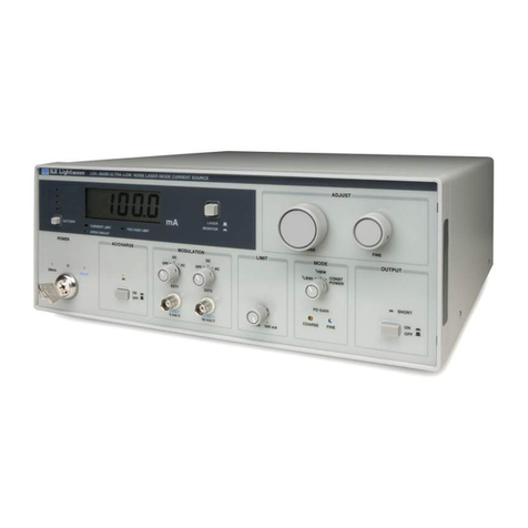
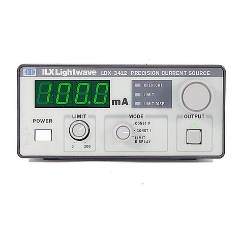
ILX Lightwave LDX-3207 User manual

-~
ARTISAN
®
~I
TECHNOLOGY
GROUP
Your definitive source
for
quality
pre-owned
equipment.
Artisan Technology
Group
Full-service,
independent
repair
center
with
experienced
engineers
and
technicians
on staff.
We
buy
your
excess,
underutilized,
and
idle
equipment
along
with
credit
for
buybacks
and
trade-ins
.
Custom
engineering
so
your
equipment
works
exactly as
you
specify.
•
Critical
and
expedited
services
•
Leasing
/
Rentals/
Demos
• In
stock/
Ready-to-ship
•
!TAR-certified
secure
asset
solutions
Expert
team
ITrust
guarantee
I
100%
satisfaction
All
tr
ademarks,
br
a
nd
names, a
nd
br
a
nd
s a
pp
earing here
in
are
th
e property of
th
e
ir
r
es
pecti
ve
ow
ner
s.
Find the Newport / ILX Lightwave LDX-3207B at our website: Click HERE

INSTRUCTION
WAL
MODEL
LDX-3207
PREC
l
SION
CURRENT
SOURCE
August 8, 1986
1986,
ILX
Lightwave Corporation
Bozeman, Montana, U.S.A.
406/586-1244
Artisan Technology Group - Quality Instrumentation ... Guaranteed | (888) 88-SOURCE | www.artisantg.com

WARRANTY
ILX LICHTMVE CORPORATICN warrants this instrument to be free from defects
in material and workmanship for a period of one year from date of
shipment. During the warranty period, we will repair or replace the unit
at our option, without charge-.
Limitation
This warranty does not apply to fuses, lamps, or batteries or to defects
caused by abuse, rnodif ication or use of the product for which
it
was not
intended.
This warranty
iq
in lieu of al
1
other warranties, expressed or imp1ied
including any implied warranty of merchantabiItity or fitness for any
particular purpose. ILX LIGHTWAVE CORPORATIW shall not be liable for any
incidental, special or consequential damages.
If a problem occurs, notify ILX LIGHTWAVE CORPORATICN, describing as
thoroughly as possible the nature of the problem including the model and
serial number. You will be given prompt attention regarding servicing or
return instructions.
Returning an Instrument
Before returning an instrument, obtain a return authorization number from
the factory. The instrument should be shipped in the original packing
carton or one that will provide equal protection. Shipping damage
is
not
covered by this warranty. Send the instrument, transportation pre-paid to
the factory, referencing the return authorization number. Repai rs wi
l l
be
made and the instrument will be returned, transportation pre-paid. Repairs
are warranted for the remainder of the original warranty or for
90
days,
whichever
is
greater.
Claims
for
Shipping Damage
When the instrument
is
received by the puchaser,
it
should immediately be
inspected for damage to the instrument or shortages on the packing
list.
If the instrument
is
damaged, a claim should be filed with the carrier. A
quotation for estimated costs of repair can be obtained from the factory.
Negotiation and settlement with the carrier must be accomplished by the
customer
.
Artisan Technology Group - Quality Instrumentation ... Guaranteed | (888) 88-SOURCE | www.artisantg.com

TABLE OF
CONTENTS
..................................
GENERAL INFORMATION
1
1.1
INTROCUCTICN
.....................................
1
.................................
1.2 PROCUCT OVERVI
EN
1
....................
1.3 AVAILABLE OPTICNS AND ACCESSORIES
1
...................................
1.4 SPECIFICATIONS 2
1.5 YOUR COMMENTS
...................................
3
OPERATION
...........................................
4
2.1 INSTALLATION
.....................................
4
2.2 AC Power Considerations
..........................
4
2.3 TiIt-Foot Adjustments
............................
4
..................................
2.4 Rack Mount
i
ng 4
2.5 LDX-3207 FAMILIAR1ZATICN
...........................
4
....................................
2.6 Front Panel 4
..............................
2.7 Power-Up Seque.nce. 6
.........................
2.8 Current Limit Adjustment 6
........................
2.9 Output Cur rent Adjustment 6
2.10 Output Connectors
...............................
7
2.11 Output Off/On Button
............................
7
2.12 ModuIation/AnaIogControl Port
.....................
8
................................
2.13 Fault Indicators 8
2.14 GPlB Rernote/Local Switch
.........................
9
2.15 Rear Panel
.....................................
9
2.16 WARM-UP
AND
ENVIRONMENTAL CCNSIDERATICNS
..............
9
2.17 OPERATING INSTRUCTICNS
.............................
9
2.18 Connecting toYourDevice
........................
9
........................
2.19 Grounding Consideration
r.
10
.......................
2.20 General Operating Procedure
11
REMOTE
PROCRAMMIM;
...................................
11
3.1 INTROUXTICN
.....................................
I1
.....................................
3.2 CAPABILITIES
11
........................
3.3 PREPARATICN FOR BUS CCNTROL
11
.......................
3.4 REMOTE PROCRAMMING PROCEWRE 13
.......................
3.5 DEVICE-DEPENDENT COMMAND SET 13
3.6 B1 (Beep Comnand)
...............................
14
3.7 Cn (Current Set Command)
.........................
14
3.8 GO (Get Instrument Status Comnand)
.................
14
3.9 On (Output Off/On Comnand)
.......................
15
3.10 INPUT SYNTAX
.....................................
15
....................................
3.11
CUTPUT
SYNTAX 16
................................
3.12 INTERFACE MESSAGES 16
.................................
3.13 EXAMPLE PROGRAMS 16
..................................
THEORY
OF OPERATION
24
4.1 OVERVIEW
........................................
24
............................
4.2 INTERNAL POWER SUPPLIES 24
...................................
4.3 CURRENT XWRCE 26
4.4 PRECISICNCURRENT SINK
.............................
26
4.5 OUTPUTOFF/CN SWITCH
..............................
27
Artisan Technology Group - Quality Instrumentation ... Guaranteed | (888) 88-SOURCE | www.artisantg.com

................
4.6
MOCULATICNflOLTAGE CCNTROL INPUT PORT
27
..........................
4.7
GPIB/I
EEE-488
BUS
CONTROL
27
MAIHTENANCE .........................................29
........................................
5.1
OVERVIW
29
......................................
5.2
CALIBRATICN
29
...........................
5.3
Recomnended Equipment
29
.........................
5.4
Environmental Conditions
29
.......................................
5.5
Wa rm.Up
30
..........................
5.6
Calibration Adjustments
30
.................................
5.7
FUSE REPLACEMENT
31
.............................
5.8
LINE VOLTAGE SELECTICN
31
......................................
5.9
DISASSEMBLY
32
.................
OPTIONAL MODEL
1205/I
EEE-488
INTERFACE
33
6.1
OVERVIEW
........................................
33
6.2
SPECIFICATIONS,
...................................
33
6.3
INSTALLATICN
.....................................
34
6.4
MAINTENANCE
......................................
35
6.5
CALIBRATICN
......................................
36
...................................
SCHEMATIC DIGRAMS
39
7.1
MAIN CIRCUIT BOARDCaPONENT LAYOUT
..................
40
............
7.2
FRONT-PANEL CIRCUIT BOARD COMPONENT LAYOUT
41
.....
7.3
MAIN CIRCUIT BOARD ANALOC SECTICN SCHEMATIC DIAGRAM
42
....
7.4
MAIN CIRCUIT BOARD DIGITAL SECTICN SCHEMATIC DIAGRAM
43
7.5
MAIN CIRCUIT BOARD POWER SUPPLl ES SCHEMATIC DIAGRAM
.....
44
...........
7.6
FRONT-PANEL CIRCUIT BOARD SCHEMATIC DIAGRAM
45
Artisan Technology Group - Quality Instrumentation ... Guaranteed | (888) 88-SOURCE | www.artisantg.com

CHAPTER
1
GENERAL
INFORMATlaY
This manual contains operation and maintenance information for the
LDX-3207 Precision Current Source and optional Model 1205 GPIB/IEEE-
488 Interface. If you want to get started right away you may want
to skip to Chapters 2 and 3 which cover Operation and Remote
Programming.
1.2
.PROOUCT
OVERVI
EW
The LDX-3207
is
a precision current source optimized for driving
laser diodes and LEDs with an output range of 0 to 200
mA
and a
compl iance voltage of 5 volts. Multiple bui
l
t-in protection
features ensure that the supply output
is
transient free and
bounded under all conditions. The output level of the 3207
is
controllable in three modes: (1) manually via a 10-turn precision
control knob, (2) through an analog voltage control/rnodulation port,
and (3) remotely via the optional model 1205 GPIB/IEEE-488
Interface.
Features of the LDX-3207 include:
Intuitive front panel layout
Highly visible green LED display
Display resolution of 0.1
rnA
Fully independent, precision current limit control
CC
-
100
KHz
voltage control/rnodulation port
"
Safe output off/on switch
Audible and visual fault condition indicators
1.3
AVAl LABLE OPTIONS
AND
ACCESSOR1ES
Opt ions and accessories avai lable for the LDX-3207 include the
following:
DESCKlPT lCN
CPIB/IEEE Interface
MODEL NUMBER
Rack mount
f
l
ange kit 31
0
Rack mount, 1/2 width
filler panel kit
Enclosure interlocking kit 339
Artisan Technology Group - Quality Instrumentation ... Guaranteed | (888) 88-SOURCE | www.artisantg.com

The
1205
interface permits GPlB
bus
control of the
LDX-3207
making
possible many automated test and measurement appl ications. For
more information on this interface option see Chapter
3
on Remote
Programning.
The LDX-3207 enclosure
is
a half-width, rack mountable module
designed to be rack mounted either by itself or interlocked with
other ILX Lightwave, X-series enclosure modules. The 300 series
accessories
l
i
sted above make possible rack mounting and
interlocking of these enclosure modules.
OUT
PUT
CUTPUT CURRENT
RASE
:
COMPLIANCE VOLTAGE:
TEMPERATURE COEFFICIENT:
NO1
SE
AND
Rl
PPLE
(Q
100nt4 output):
DlSPLAY
TYPE
:
MAX
I
MUM
R
EADI
NG
:
ACCWACY (2
5
C
)
:
TEMPERATURE COEFFICIENT:
CURRENT L
l
M
l
T
RANG
E
:
ACCURACY
:
0 to 200 mA, floating.
>
5
volts.
<
100 PPM/C ambient.
<
0.01
%
rms, typical.
3-1/2 digit LED display.
199.9 mA.
+/-
0.1 m4.
<
100 ppm/C.
0 to 200 mA.
+/-
1.0 mA, independent of output
compl iance voltage.
Cur rent
l
imit adjustment does not interfere with normal
output operation (a dumny load
is
not required). Current
l
imit setting takes precedence in al
l
modes of operation.
MCCULAT
l
CN /MILTAGE CCNTROL
INPUT: Differential input.
TRANSFER FUVCTICN: 100 mA/V.
TRANSFER FLNCTICN ERROR:
<
1%
BMIDTH
(3db, lout
=
50
inA
P-P):
CC
to 100
KHz.
IEEE-488
BUS
IMPLEMENTATION (with optional model 1205 interface).
GENERAL
:
Implements talker/l istener
f
unctions.
INTERFACE MESSAGES: REN,DCL, LLO, GTL, SDC
Artisan Technology Group - Quality Instrumentation ... Guaranteed | (888) 88-SOURCE | www.artisantg.com

DEVICE
DEPENDENT
COMMND
STRUCTURE:
Command
00,Ol Funct ion
Switch output: O=off, l=on
Set output current
to
nnn.nnn
nt4.
Beep.
Get error status.
I
SOLATICN: Instrument is optical Iy isolated
f
rom
IEEE-488
bus.
CONTROL RESOLUTION: 12 bi
t
s
(0.05
m4).
CCNTROL ACCURACY:
+/-
0.1
mA.
GENERAL
POWER REQUIREMENTS:
SIZE:
TEMPERATURE WE:
WARMUP
:
COW
ECTORS
:
1.5
YOUR
COMM
WTS
105-125V or 210-250V (jumper
selectable), 50-60
Hz.
88
mm
x
21
mm
x
269
mn
(3.46'
x
8.36'
x
10.6')
0
to
50
C
operating,
-40
to
70
C
storage.
1 hour to rated accuracy.
Output, binding post (isolated
from chassis ground), modulation
input, BNC (differential input).
Our goal is to make the best laser diode instrumentation available
anywhere. To achieve this end we need your ideas and comnents on
ways we can improve our products.
We
invite you to contact us at
any
time
with your suggestions.
Artisan Technology Group - Quality Instrumentation ... Guaranteed | (888) 88-SOURCE | www.artisantg.com

CHAPTER
2
OPERATION
2.1 INSTALLATION
2.2
AC
Power Considerations
The LDX-3207 can be configured to operate at line voltages ranging
from 105-125
VAC
or 210-250
VAC.
Normally, this
is
done at the
factory and need not be changed before operating the instrument.
However, check to be sure that the voltage printed on the rear
panel of the instrument matches the power-line voltage in your
area. Refer to Chapter
5
(Maintenance) if
it
is
necessary to
reconfigure the input voltage range.
To avoid electrica
l
shock
hazard, connect
the instrument only to properly earth-
grounded, 3-prong receptacles. Failure to
observe this precaution can result in severe
injury or death in the event of an internal
ma
l
function.
2.3 Ti
l
t-Foot Adjustment
The LOX-3207
is
supplied with special, extendable front legs. The
front of the instrument can be tilted up for better viewing by
rotating the legs domward until they snap into the down and
position.
2.4 Rack Mounting
The LDX-3207 may be rack mounted singly by instal
I
ing a rack
ocked
mount
flange on one side of the enclosure and a 1/2 width filler panel on
the other side. Alternatively, two X-series enclosures can be
interlocked side-by-side and then rack mounted as a unit by using a
pair of rack mount flanges. Detailed mounting instructions are
supplied with all rack mount accessory kits. Refer to Section
1.3
for applicable rack mount accessory part numbers.
2.6 Front Panel
Figure 2.1 shows the layout of features on the front panel.
Generally you wi
l
l
find the LDX-3207 controls and features to be
simple and intuitively easy to use. However
,
the fo
l
lowing
paragraphs provide descriptions of each front panel feature.
Artisan Technology Group - Quality Instrumentation ... Guaranteed | (888) 88-SOURCE | www.artisantg.com

AUDIBLE TONES:
Repeating
1
second tone indicates current
limit condition.
Single
3
second tone indicates that
an
open
circuit condition has occurred.
INSTRUMENT STATUS INDICATORS:
OPEN CKT
Output is an open c~rcuitor requires greater
than
5
volt compliance.
LIMIT
Output is in current limit mode.
LIMIT DlSP
Display is reading the current limit settmg.
DISPLAY MAINOUTPUT
ADJUSTMENT KNOB
PUSH
TO
VIEW
OUTPUT
TERMINALS
GPIB/IEEE-488 VOLTAGE CONTROL
REMOTE MODE INPUT PORT
INDICATOR AND
LOCAL SWITCH
Artisan Technology Group - Quality Instrumentation ... Guaranteed | (888) 88-SOURCE | www.artisantg.com

2.7
Power-Up Sequence
With the
LDX-3207
properly connected to an
AC
power source,
pressing the KWER off/on switch causes the unit to initiate
its
power-up sequence. During this sequence the audible fault
indicatior (beeper) will sound momentarily and the display may
briefly indicate a non-zero reading. However, during this period
the output terminals are unconditionally shorted and the output
.
off/on switch
is
inhibited for several seconds preventing current
from leaving the output terminals. After approximately two seconds
the disply should read 0.0
mA.
2.8 Cur rent Limit Adjustment
The front panel LlMlT control setting determines the maximum output
current for all modes of operation.. This current limit
.is
set by
rotating the LlMlT knob to the desired value. The current limit
setting can be estimated by observing position of the knob indicator
line relative to the 0 and 200
m.4
markings or determined precisely
by momentarily depressing the knob. Once the LlMlT knob has been
depressed, the display wil
l
read the current limit setting for
approximately
5
seconds. During this 5 second interval the LlMlT
DlSP (limit display) indicator remains on.
The current limit setting
is
independent of the voltage drop of the
device connected to the output of the 3207 and therefore no dumny
load
is
required for precise adjustment of the current limit.
Furthermore, since the current limit circuitry
is
fully independent
of the main current control, the current limit can be adjusted
safely even v~hilethe output
is
active.
2.9 Output Current Adjustment
Primary output current control
is
provided by the large knob
located on the front panel of the LDX-3207. This knob
is
connected
to a precision 10-turn potentiometer and can easily be used to
achieve a setting resolution of 0.05
nt4
(or 0.02
mA
with some care).
Depending on whether the 3207
is
in LOCAL or REMOTE mode, the
output current
is
also affected by any control voltage applied to
the MOD input connector and comnands sent to the optional
CPIB/IEEE-488 interface (when installed). Under a
l
l
modes of
operation the output current
is
unconditionally limited to the value
set by the LlMlT adjustment.
Local Mode
-
When initially turned on the LDX-3207
is
in LOCAL
mode. In this operating mode the output current
is
determined by the setting of the main output current
adjustment knob and any control signal applied to the MOD
input connector. The control level generated by the control
knob
is
summed with the control signal applied to the
MOD
input. In effect the control knob acts as a
DC
bias. (offset)
adjustment to the signal applied to the
MOD
input.
Remote Mode
-
When the model 1205 CPIB/IEEE-488 interf-ace
is
installed, the LDX-3207 may be operated in REMOTE mode. This
Artisan Technology Group - Quality Instrumentation ... Guaranteed | (888) 88-SOURCE | www.artisantg.com

mode o,f operation
is
activated in response to commands sent
to the
3207
via the interface. Once in REMOTE mode, the
output cur rent level
is
determined by appropriate commands
sent over the CPIB/IEEE-488 bus. For example, the cmand
'CSO.01'
will cause the output of the
3207
to go to
50.01
m4
to within the control accuracy of the interface. In this mode
of operation the main current adjustment knob and MOD input
are disabled. The
3207
may be returned to
LOCAL
mode by
rnomentari ly pressing the
LOCAL
button. For more information
on the REMOTE mode of operation refer to Chapter
3.
2.10
Output Connectors
The front panel output connectors supplied with the
LDX-3207
are
two standard binding posts on
0.75
inch centers. Current flows out
of the red connector and returns via the black connector. These
output connectors are fully floating with respect to the chassis
ground.
2.11
Output Off/On Button
The output off/on switch
is
located just to the left of the output
terminals and
is
used to turn the output of the
3207
off and on.
When the output
is
active, the
LED
indicator just above the button
is
lit
indicating that current
is
flowing from the positive to
negative terminals. The off/on button has a toggling action: if the
ouput
is
off, pressing
it
will cause the ouptut to come on, and vice
versa.
When the ouptut
is
off, a low impedence shunt
is
active across the
output terminals. In this state
it
is
safe to connect or remove
sensitive devices from the
3207
even though power supply itself
is
on. Turning the output on initiates a slow turn-on sequence that
takes a few seconds to complete. During this period, the impedence
of the internal shunt slowly increases diverting current through
the output terminals.
When the
3207
is
first turned on, the off/on button
is
inhibited for
several seconds. This forces the internal, low impedence shunt to
remain active across the output terminals until the
3207
control
circui
ts
are stabiIized. Additionally, there are two other
conditions that wi
l
l
automatical ly cause the output to reset to the
off state:
Power Drop-outs
-
,K
line power drop-outs lasting more than
about
10
msec wi II trigger an internal power monitor and
cause the output to switch unconditional ly to the off state.
This sequence
is
also initiated when the
3207
is
switched off
or unp
l
ugged.
Open Circuit
-
If the compliance voltage of the externally
connected circuit exceeds about
6
volts, the output
is
switched to the off state and OPEN
CKT
indicator
is
activated.
Most commonly this occurs when the output off/on button
is
pressed without a load attached. (See also Section
2.13)
Artisan Technology Group - Quality Instrumentation ... Guaranteed | (888) 88-SOURCE | www.artisantg.com

If either of these conditions occur, the output
may
be turned on
again
by
simply
pressing the front-panel output off/on switch.
2.12 Modulation/Analog Control Port
The modulation/analog control port provides a means of modulating
the output current of the LDX-3207 with
a
3 db bandwidth of
DC
through 100
KHz.
Input connection
is
provided by an isolated BNC
connector designated MOD on the front panel. This connector
provides a true differential input and need not use the same ground
and the output terminals. The only restriction
is
that the control
signal applied to the MOD connector should be within approximately
12 volts of the output terminals.
Modulation/Analog Control Port
(MOD Input)
TRANSFER FLNCTICN 100 mA/vo
l
t
CCNTROL BANDWIDTH
(3
db) 100
KHz
INPUT IMPEDENCE 1,000 ohms
INPUT POLAR
l
TY center pin, POSITIVE
she1
I,
NEGATIVE
Any control signal applied to the MOD input sumned with the control
signal due to the main current control knob setting. The transfer
function of the modulation/vol tage control input
is
+I00 mA/vol
t
with the center pin of the input
f3NC
connector being positive with
respect to the shell. Thus, with the main current control knob set
to 100
m4
and
a
0.5 volt input present at the MOD input, the
resulting current output would be 150
m4.
The MOD input, like the main current control knob,
is
disabled when
the 3207
is
in REMOTE mode.
2.13 Fault Indicators
The LDX-3207 has two visual front-panel fault indicators, OPEN CKT
and LIMIT, and an audible tone that are used to identify open
circuit and current limit conditions.
OPEN CKT indicates that the cmpliance voltage required at
the 3207 output terminals has exceeded approximately
6
volts.
Most comnonly this happens when there ii'no load attached to
the output or the load becomes disconnected when the output
is
active. When an OPEN CKT condition occurs, the 3207
outputs
is
automatically turned off, the OPEN CKT indicator
latches on, and a tone sounds for approximately
3
seconds.
The OPEN CKT indicator wil
I
remain on until the o~iput
is
turned on again either manually or via the CPIB/IEEE-488
interface.
LIMIT indicates that 3207 output
is
being limited to the
setting of the front panel LlMlT knob. When a LlMlT condition
occurs, the LlMlT indicator
is
lit
and a tone
is
repeatedly
Artisan Technology Group - Quality Instrumentation ... Guaranteed | (888) 88-SOURCE | www.artisantg.com

sounded. Due to the unique design of the 3207, the LlMlT
indicators are operative even while the ouput
is
off.
If the 3207
is
repetitively driven' into the current limit mode by a
time varying signal applied to the MOD input, the LlMlT indicator
will light and a tone will sound. The tone may sound continuous or
intermittent depending on the frequency of the modulation signal.
With the 1205 interface installed, the status of both the OPEN
CKT
and LlMlT indicators may be read back over the CPIB/IEEE-488 bus.
For more information on this feature see Chapter 3.
2.14 CPlB Remote/Local switch
The GPlB LOCAL switch
is
used to return the LDX-3207 to local
control after
it
has been put in REMOTE mode via the
CPIB/IEEE-488 bus. In REMOTE mode, both the main current
control knob and the MOD input are disabled and the 3207 output
may be controlled only via the CPIB/IEEE-488 bus. This control
mode
is
available only when the optional model 1205 CPIB/lEEE-488
interface
is
installed. For more information see Chapter
3.
2.15 Rear Panel
The rear panel contains the AC power input connector, fuse holder,
9-pin D-connector, and serial number sticker. When the optional
model 1205 CPIB/IEEE-488 interface
is
installed, the rear pane.1
additionally contains the standard GPIB/IEEE-488 bus connector and
address selecto'r switch. Output current
is
available at the 9-pin
D-
connector, j
104.
With the 3154 Photodiode Feedback module
i~siaJ\t$,
-
1104
.is
util.ized for the photodiode input signal
is
utilized in a LDS-7000 system configuration,
flOaf
a\!;
contains an interlock which will disable the current output unless
defeated. See Section 2.18 for detailed information. For
information on the fuse replacement see Section 5.7. For
information regarding programming in preparation for using the
CPIB/lEEE-488 interface see Section 3.3.
2.1
6
WARM-UP AND ENVIRONMENTAL CONSIDERATIONS
The LDX-3207 should be operated at an ambient temperature between
0 and 50 degrees centigrade. Storage temperatures should be in the
range -40 to 70 C. In order to achieve rated accuracy the LDX-3207
-
should be allowed to warm up for about 1 hour before use.
2.17
OPERATING INSTRUCTIONS
2.18 Connecting to Your Device
When connecting laser diodes and other sensitive devices to the
LDX-3207 we recommend that the 3207 should be powered-up with
the output off. In this condition a low impedence shunt is active
across the output terminals. When disconnecting devices
it
is
only
necessary to turn the output off.
Artisan Technology Group - Quality Instrumentation ... Guaranteed | (888) 88-SOURCE | www.artisantg.com

Svstem Interlock and Photodiode Feedback
The 9-pin connector (J104) on the rear panel contains the current
supply output and earth ground. With the 3154 Photodiode Feedback
module installed, the photodiode signal
is
input at the connector.
When the LDX-3207
is
part of a system, then an interlock
is
incorporated at j104 and
is
defeated by internal wiring located
inside the hood of the supplied interconnect cable. In standard
units the interlock
is
internally defeated. If the interlock feature
is
required, please contact ILX Lightwave for information.
When the interlock function
is
to be utilized, th-en a switch must be
wired across pins 1.and 2 of 1104. To do this, open the cable hood
located at the end which connects to 1104. The connections are
made across pins
1
and 2 of the cable connector. When the desired
wiring has been installed, replace the hood on the cable. The
switch must be electrically isolated from all other circuits including
earth ground. Refer to Fig. 2.2 for more information. For detail on
the 3154 Photodiode Feedback module, please refer to the enclosed
manual.
2.19 Grounding Considerations
he
outputs of the LDX-3207 are iso1ate.d from chassis ground
allowing either output terminal to be grounded at the user's option.
2.20 General Operating Procedure
The LDX-3207 can be operated in several modes. The following
operating procedure
is
applicable to most common usage.
1. Plug the 3207 into an AC power source supplying the correct
voltage and frequency for your unit (refer to the rear panel serial
number sticker for the correct ratings).
2. Turn on the 3207 and allow one hour warm-up period for rated
accuracy operation.
3. Momentarily depress the LIMIT knob and then adjust
it
to the
ma.ximum current that you wish to source.
4. With the output off, make the necessary external circuit
connections. Double check to ensure that the correct polarity has
been observed when connecting to laser diodes and other devices
sensitive to being reverse biased.
5.
Switch the output on and adjust the current to the desired DC
level using the main current setting knob.
6.
As needed, connect the modulation/control signal to the MOD
input.
At any time during the operation of the 3207, the output current
limit setting may be viewed by momentarily depressing the LIMIT
Artisan Technology Group - Quality Instrumentation ... Guaranteed | (888) 88-SOURCE | www.artisantg.com

Interlock
(-1
--
Interlock
(+)
Earth Ground
itor Photodiode
(-)
itor Photodiode
(+)
Laser Anode
(RED)
Laser Cathode
(
BLAC
K)
LDX-3207 D-Connector Pinout (j104)
Fig.
2.2
Artisan Technology Group - Quality Instrumentation ... Guaranteed | (888) 88-SOURCE | www.artisantg.com

CHAPTER
3
REMOTE
PROGRAMMING
3.1
INTRODUCTION
When properly installed, the model 1205 GPIB/IEEE-488 interface turns the
LDX-3207 into a programable current source for use with the
IEEE
Standard
488-1978 interface bus. This arrangement permits the LDX-3207 to be
controlled by most computers and makes possible a wide variety of
automated test and measurement appl ications.
To implement IEEE-488 bus control you wi ll general
l
y need to have an
I
EEE-
488 interface adapter in your host computer. These adapters along with
appropriate software are readily avai lable frorn several manufacturers and
for most popular computers. This manual assumes that you. have a basic
knowledge of the CPIB/IEEE-488 interface bus and
its
use for instrument
control. However, if you need application assistance feel free to call ILX
Lightwave at the number listed at the front of this manual.
<
3.2
CAPABILITIES
The model 1205 CPIB/IEEE-488 interface provides control of the LDX-3207
output current level with 12 bit (0.05
m4)
resolution as we1
l
as control
over the output off/on switch and audible tone. In addition, the
instrument status (OPEN CKT, LIMIT,
C(\1,
REMOTE) can be read back over the
bus. Other features include:
A
sinple and predictable comnand set
35 msec comand throughput
Full loc
al/remote capability including LOCAL LOCKCUT
In addition to
supports the fol several device dependent comnands the 1205 interface
lowing interface messsages: REN, EL, LLO, CTL and
SIX.
3.3
PREPARATION
FOR
BUS CONTROL
Once the 1205 interface has been properly installed in the LDX-3207 (see
Section 6.3), the following steps should be taken to prepare the instrument
for bus control:
1.
Turn off the power to the LDX-3207 and set the GPIB/IEEE-488
interface address switch as shown in Figure
3.1.
The
address
you
choose should be different from that of any other instrument
connected to the bus.
2. Plug the GPIB/lEEE-488 bus cable into the LDX-3207 rear panel
connector and secure
it
with the plug-mounted screws.
3.
Turn on the instrument.
Artisan Technology Group - Quality Instrumentation ... Guaranteed | (888) 88-SOURCE | www.artisantg.com

SWITCH POSITIONS
ADDRESS 1
2
3
4
.5
Fipure3.1. Bus Address Selector Switch Settings
Artisan Technology Group - Quality Instrumentation ... Guaranteed | (888) 88-SOURCE | www.artisantg.com

3.4
REMOTE
PROCRAMM
ING
PROCEDURE
In general the LDX-3207/1205
is
programmed by simply sending it an ASCII
string of characters that
is
comprised of one or more commands. A simple
example would be:
'01C50.2' In this example the 3207 output
is
turned on and
the current set to 50.2
mA.
On receiving this comnand string the 3207
is
placed in remote mode, the
slow turn-on sequence
is
initiated (if the output
is
not already on), and
the current level
is
comnanded to go to 50.2
mA.
In order to insure that the 3207 has successfully executed these
instructions
it
may be desirable to read back the status of the instrument.
Thi
s
can be accomp
l
i
shed us
i
ng the GO comnand:
'GO
'
Loads the instrument status into the interface
output buffer.
Transmission of this comnand should be fol lowed by execution of an
instruction to read ASCII data from the interface. The interface will
respond by sending
a
string of five ASCll characters that indicate whether
or not the last cormand was understood and the status of the f ront panel
indicators: OPEN CM, LIMIT,
CN,
REMOTE. For example, the string 00011
indicates that the previous comnand was understood and executed and that
the instrument
is
operating normal ly in remote mode with the output on.
The
GO
comnand
is
described fully in Section 3.7.
3.5
DEVICE DEPWENT COMMAND SET
The complete LDX-3207/1205 device-dependent comnand set
is
sumnar ized in
Table 3.1 below. Each of the listed commands
is
described fully in
Sections 3.6 through 3.9.
On receiving any of the device dependent comnands the LDX-3207/1205
is
placed in REMOTE mode.
TABLE 3.1
LDX-3207/1205 DEVICE-DEPENDENT COMMAND SET
B1 Triggers the audible tone in the LDX-3207
Cn Sets the output current of the LDX-3207
GO Loads the instrument status into the interface
output buffer
On Turns the LDX-3207 output off or -on
Artisan Technology Group - Quality Instrumentation ... Guaranteed | (888) 88-SOURCE | www.artisantg.com

3.6
I31
(Beep
Comnand)
On receiving the
61
comnand the audible tone in the 3207
is
triggered. The
duration of the tone
is
approximately
3
seconds.
3.7
Cn (Current Set Comnand)
The Cn comnand
is
used to set the output current of the LDX-3207 over the
GPIB/IEEE-488 bus. The numeric field 'n' following the comnand letter 'C'
may be formatted in a number of ways. The examples in Figure 3.2
illustrate both correctly and incorrectly formatted comnands.
CORRECT INCORRECT
C50 CB50
C123.11 C%lOO
Figure 3.2. Cn Comnand Format Examples
Note that the numeric field itself must be an integer or decimal number
that has a value in the range of 0 to 200.
Upon receiving
a
correctly formatted Cn comnand, the LDX-3207 wi
ll
switch
to remote mode (if
it
was previously in local mode) and produce an output
current equal to the value of the numeric field in milliamps. That
is,
the
comnand C25 will result in an output of 25.0 milliamps. If the Cn cmand
is incorrectly formatted, the LDX-3207 will
still
switch to remote mode (if
it
was previously in local mode) but the remote mode output level wil
l
remain at its previously set level. Additional Iy, the software comnand
error flag
is
set whenever a comnand
is
received that cannot be
-
interpreted. This error flag may be read using the GO comnand (see Section
3.7).
The 1205 GPIB/IEEE-488 interface has a 12 bit (0.05
m4)
analog control
resolution and an accuracy of 0.7
%
or better.
3.8 GO (Get lnstrurnent Status Comnand)
The
GO
cannand
is
used to read the LDX-3207/1205 instrument status over
the interface bus. Upon receiving the GO comnand the 1205 interface
switches the LDX-3207 to remote mode (if
it
was previously in local mode),
reads the status of the internal software comnand error flag, the OPEN
CKT, LIMIT, REMOTE, and
(34
front-panel indicators and then loads
appropriate ASCll characters into an output buffer. The
5
character ASCll
string generated by the
GO
comnand may be read back over the bus by
Artisan Technology Group - Quality Instrumentation ... Guaranteed | (888) 88-SOURCE | www.artisantg.com
This manual suits for next models
1
Table of contents
Other ILX Lightwave Portable Generator manuals

ILX Lightwave
ILX Lightwave LDC-3926339 User manual

ILX Lightwave
ILX Lightwave LDX-3200 Series User manual

ILX Lightwave
ILX Lightwave LDX-36000 Series User manual

ILX Lightwave
ILX Lightwave LDX-3620 User manual

ILX Lightwave
ILX Lightwave LDX-3620B User manual

ILX Lightwave
ILX Lightwave LDX-3412 User manual
Popular Portable Generator manuals by other brands

K&S BASIC
K&S BASIC KSB 30i S owner's manual

Craftsman
Craftsman 919.670041 owner's manual

Powermate
Powermate CX6500E owner's manual

Generac Power Systems
Generac Power Systems 17,500 WATT Warranty information booklet

Mosa
Mosa Magic Weld 200 Use and maintenance manual

Champion
Champion 41537 Owner's manual & operating instructions