Image Engineering GEOCAL User manual
Image Engineering GmbH & Co. KG · Im Gleisdreieck 5 . 50169 Kerpen . Germany
T +49 2234 2273 99 99 1-0 . F +49 2234 2273 99 99 1-10 . www.image-engineering.com
GEOCAL
User Manual
1. December 2020
Image Engineering
Seite 2von 15
Content
1INTRODUCTION............................................................................................................. 3
Intended use............................................................................................................. 3
General safety information........................................................................................ 3
2GETTING STARTED....................................................................................................... 4
Scope of delivery ...................................................................................................... 4
Commissioning ......................................................................................................... 4
3OPERATING INSTRUCTIONS HARDWARE.................................................................. 5
GEOCAL................................................................................................................... 5
Diffractive Optical Element (DOE)............................................................................. 5
Camera settings........................................................................................................ 5
3.3.1 Camera position and suitable lenses.................................................................. 6
3.3.2 Exposure............................................................................................................ 7
4OPERATING INSTRUCTIONS SOFTWARE .................................................................. 8
Installing GEOCAL software...................................................................................... 8
Configuration File (XML) ........................................................................................... 8
Loading images for analysis.....................................................................................10
Image analysis.........................................................................................................10
Saving results ..........................................................................................................12
Logging....................................................................................................................12
Quit..........................................................................................................................12
TRADEMARK AND COPYRIGHT............................................................................12
5ADDITIONAL INFORMATION .......................................................................................13
Disposal instructions................................................................................................13
6DATA SHEET ................................................................................................................14
Overview..................................................................................................................14
Features...................................................................................................................14
6.2.1 [Hardware] Integrating sphere, Mount...............................................................14
6.2.2 Illumination........................................................................................................14
6.2.3 Software............................................................................................................14
General description hardware ..................................................................................15
Requirements on the device under test (DUT) .........................................................15

Image Engineering
Seite 3von 15
1 INTRODUCTION
Important information: Read the manual carefully before using the device.
Inappropriate utilization may cause damage to the device.
Intended use
GEOCAL consists of an illuminating hardware device and software for geometric calibration of camera
systems. The GEOCAL software is used for calculating the calibration parameters from a single image
taken with a camera system of the point grid generated by the GEOCAL hardware device.
•Only suitable for indoor use.
•Place the system in a dry and constant tempered environment. Avoid high air humidity.
General safety information
WARNING! GEOCAL uses a laser diode for illumination.
LASER RADIATION CLASS 1M LASER PRODUCT
•Do not stare into beam
•Do not view directly with optical instruments
•Do not open the housing of GEOCAL under any circumstances

Image Engineering
Seite 4von 15
2 GETTING STARTED
Scope of delivery
•GEOCAL hardware device
•Latest software version on USB storage device
•Power supply + cable
•USB cable (type B to type A)
•Test report
Commissioning
•Remove the packaging material.
•The power socket is located on the left-hand side of the device next to the USB type B socket.
The main power switch is located on the right-hand side. Connect GEOCAL to a power outlet
and switch it on.
Please note: the blue LED next to the power switch indicates that the power line is active and
GEOCAL is ready for operation.
•Install the latest GEOCAL software (Windows, 64bit)
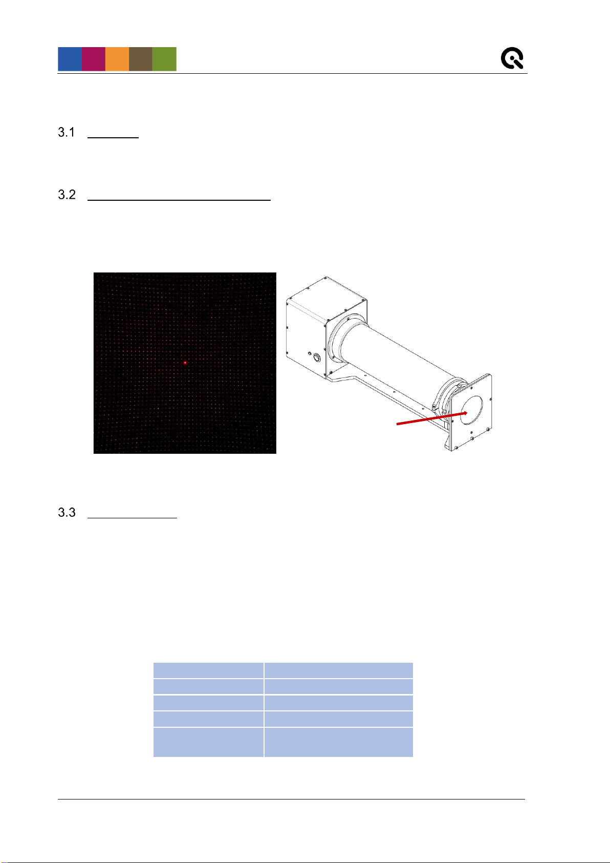
Image Engineering
Seite 5von 15
3 OPERATING INSTRUCTIONS HARDWARE
GEOCAL
After switching on, GEOCAL is ready for use. No warm-up phase is required.
Diffractive Optical Element (DOE)
A diffractive optical element (DOE) is used to split the incoming beam of light and generate a calibration
grid of evenly distributed light spots with a wavelength of 633 nm. The DOE is mounted on the front of the
GEOCAL device (visible glass plate mounted in circular cutout, see Figure 2).
Camera settings
Set the camera to manual exposure mode. If manual mode is not available, use the automatic exposure
mode. For best results, the image should be saved in a lossless image format. TIFF format is
recommended, PNG and JPEG (lossy) are also supported. If you convert RAW image data to another
format, make sure the image is being debayered in the process.
Auto focus must be turned off. Since GEOCAL uses a collimated light beam virtually originating from
infinity, the appropriate focus distance will be near infinity. Using manual focus, make sure that the
camera is focused on the light points.
Exposure program
Manual
Aperture
No default value
ISO Speed
Lowest value (e.g.,100)
Auto focus
Off
File type
TIFF recommended, PNG
and JPEG also supported
DOE
Figure 1: Calibration grid
(the brightest spot marks the center)
Figure 2: Location of the DOE
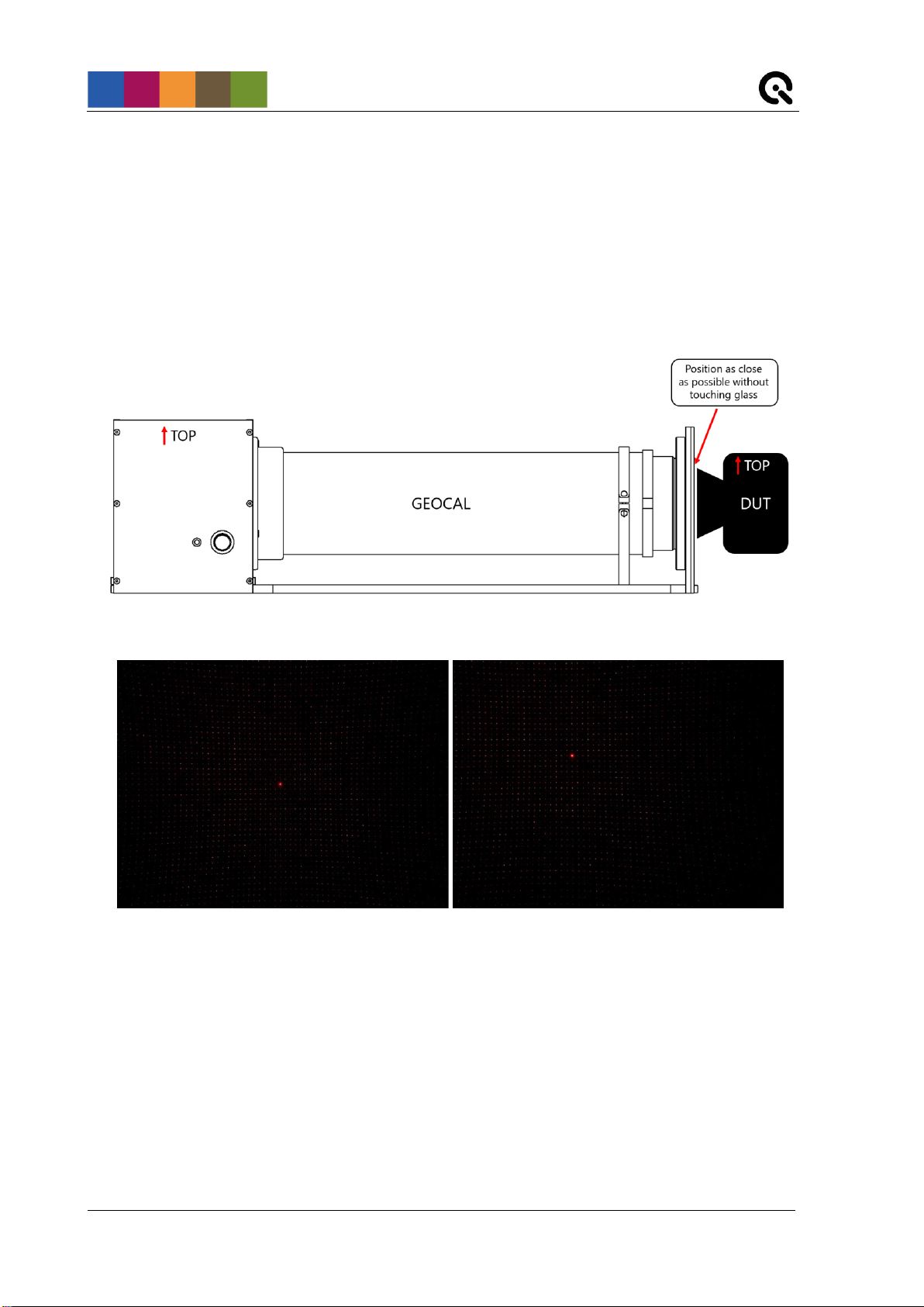
Image Engineering
Seite 6von 15
3.3.1 Camera position and suitable lenses
Place the camera in front of the diffractive optical element that is located in the circular opening on the
front of GEOCAL.
The camera can be placed directly in front of the DOE, no minimum distance is needed (view Figure 3
below). The principal axis of the lens should be aligned approx. perpendicular to the DOE. Do this by
aligning the 0th diffraction order, which is the brightest spot in the center of the grid, with the center of the
image. See Figure 4 for reference. Make sure that the point grid covers the whole image and that the
border of the DOE is not visible.
The top side of Geocal and the top side of the camera must have the same orientation. A rotation of the
camera around the optical axis of approx. +/- 2° will be tolerable.
No further alignment steps are necessary. The mapping of the light points is not influenced by the
translation of the camera. The rotation of the camera to the DOE is part of the calibration and is
determined during the process and reported as part of the result.
The front element of the lens must not be larger than 77 mm in diameter in order to capture the point grid
in full format. GEOCAL has been tested using various lenses with a field of view between 30° and 120°.
Avoid using lenses that exceed or fall below these values, otherwise, no reliable calibration results can be
guaranteed.
Figure 3: Setting the distance between camera and GEOCAL
Figure 4: Good alignment (0th order in center of image) Bad alignment (0th order far off center)
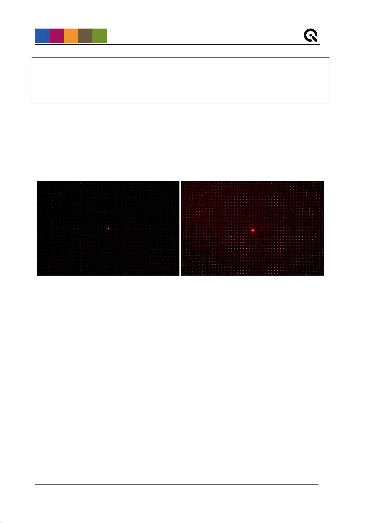
Image Engineering
Seite 7von 15
Note: Please use caution when positioning the camera. The DOE is made of glass and has a
thickness of only 1.5 mm.
Ensure that the calibration is performed in a dark environment to avoid stray light, reflections, or
similar interfering factors.
3.3.2 Exposure
For best results, the exposure should be selected so that the individual light points are not saturated (i.e.,
no white pixels or a minimal amount of white pixels in the center of each point) with excepton of the 0th
diffraction order. The 0th order will always be much brighter than the points surrounding it. See Figure 5
below for an example.
Depending on your camera you might encounter different problems:
The exposure time of my camera cannot be set short enough to avoid saturation.
Possible solutions:
- Set the ISO to the lowest native value available (ISO 100 for most cameras)
- Stop down the aperture if possible
- If the image is still too bright, you could use an ND-Filter to reduce the amount of light
reaching the image sensor
The intensity dropoff is too steep towards the edges of the image. There are no more points
visible.
This problem may occur for ultra wide-angle lenses. If the images can not be properly analyzed, try the
following.
Generate an HDR image by taking multiple images of the point grid using a range of exposure times (do
not change aperture settings in this case) and combine them to a high dynamic range image in order to
achieve more or less uniform exposure across the entire sensor. Do not change the orientation of the
camera in between images because the points would be no longer aligned to one another through
multiple images.
Figure 5: Suitable exposure (dark backgroumd, small points) Exposure too bright (red background, larger, saturated points)

Image Engineering
Seite 8von 15
4 OPERATING INSTRUCTIONS SOFTWARE
The GEOCAL software enables you to perform a complete calibration of your camera system in a matter
of seconds.
The results can be saved as CSV or XML files.
Installing GEOCAL software
•Execute the GEOCAL installer (GEOCAL_Vx.x.x.exe, 64 bit) and follow the instructions.
•The software is now ready for use.
Configuration File (XML)
A standard config file will be installed with the software. If your calibration does not require very specific
settings you do not need to load a config file or manipulate the existing one.
If you do need to make adjustments, the parameters of the config file are listed below.
•Control Parameter: MinF
This parameter describes the stop strategy, at which optimization value the analysis is stopped
(0.0…10.0 – default: 1.0)
The smaller the value, the more accurate the analysis becomes, but the analysis time also
increases.
•Control Parameter: MinDelta
This parameter describes another stop strategy. When the change of the optimization value
between two iterations is less than the delta, the analysis stops (0.0...10.0 - default: 1e-7).
The smaller the value, the more accurate the analysis becomes, but the analysis time also
increases.
•Analysis Parameter: angles Alpha and Beta
These angles describe the orientation of the diffractive optical element to the incident expanded
and collimated beam of light. They are determined during the acceptance procedure at Image
Engineering and written in the config file. These values may not be changed unless the diffractive
optical element has to be replaced.
Nevertheless, they can, for example, be set to zero for troubleshooting.
•Analysis Parameter: angles Omega (roll), Phi (pitch), Kappa (yaw)
These angles describe the orientation of the device under test to the diffractive optical element.
These values are determined during calibration and output as results. Nevertheless, they can be
set to a fixed value for troubleshooting.
•Analysis Parameter: Radial Distortion Coefficients 1-5
The radial distortion coefficients model this type of distortion. The distorted points are denoted as:
xdistorted = x(1 + k1*r2+ k2*r4+ k3*r6+ k4*r8+ k5*r10)
ydistorted= y(1 + k1*r2+ k2*r4+ k3*r6+ k4*r8+ k5*r10)
These values are determined during calibration and output as results. However, they can be set
to a fixed value for troubleshooting.

Image Engineering
Seite 9von 15
•Analysis Parameter: Tangential Distortion Coefficients 1+2
The tangential distortion coefficients model this type of distortion. The distorted points are
denoted as:
xdistorted = x + [2p1xy + p2(r² + 2x²)]
ydistorted = y + [p1(r² + 2y²) + 2p2xy]
These values are determined during calibration and output as results. However, they can be set
to a fixed value for troubleshooting.
•Analysis Parameter: Focal Length Xand Y
The focal length values of the device under test in X and Y are determined during calibration and
output as results in pixel dimensions. Nevertheless, they can be set to a fixed value for
troubleshooting.
•Analysis Parameter: Skew coefficient
The skew coefficient is set to 0 by default. It is non-zero if the image axes are not perpendicular.
•Analysis Parameter: Principal Point
The principal point (optical center) describes the point where the optical axis of the camera lens
intersects the image sensor. It is determined during calibration and output as a result.
Nevertheless, it can be set to a fixed value for troubleshooting.
To make changes to the standard config file, open it in a text editor. It is advised to make a copy of the
standard version before editing it.
Editing Control Parameters:
Example:
<MinF Use="false">0.1</MinF>
The “Use” flag indicates if the following value is used for the calibration procedure. If it says “false”, it is
not used and the standard value is used instead. To use a custom value, write “true” instead of “false”
and change the value (“0.1”in this example) as desired. The new value will be used in every calibration
until you set the “Use” flag back to “false” again.
Editing Analysis Parameters:
Example:
<Alpha SetToInvariant="false" Unit="Degree">0</Alpha>
The “SetToInvariant” flag indicates if the following value is calculated during calibration or set to a fixed
value. If it is set to “false”, the value is calculated in each calibration. To set it to a fixed value, write “true”
instead of “false” and change the value (“0” in this example) as desired. The new value will be used in
every calibration until you set the “SetToInvariant” flag back to “false” again.
Loading a config file:
Click File →Load configuration (ctrl+c) →navigate to the folder containing the file →select the file and
click “open”.

Image Engineering
Seite 10 von 15
Loading images for analysis
Click File →Load images (ctrl+o) →navigate to the folder containing the images →select one or multiple
images and click “open”.
In the current state, the software supports the analysis of 8bit and 16bit images.
The following file types are supported (debayered images): .TIFF, .JPG, .PNG
Images for analysis need to be taken so that the point grid fills the sensor completely.
Image analysis
•Image selection: Select an image from the list in the “Image data” section (1). The image will
then be visualized in the “Image” section (4) under the “Image” tab. You can zoom into and out of
the image using your mouse wheel. The zoom will be centered around the position of your cursor.
•Point detection: Detect the points in the image by pressing the “Detect” button in the “Detection
& analysis” (2) section.
Detection is finished when the progress bar at the bottom of the window (5) reaches 100%. By
pressing “Show Detected Grid” next to the progress bar, you can display a visualization of the
detected/undetected points.
Figure 6: Software user interface overview
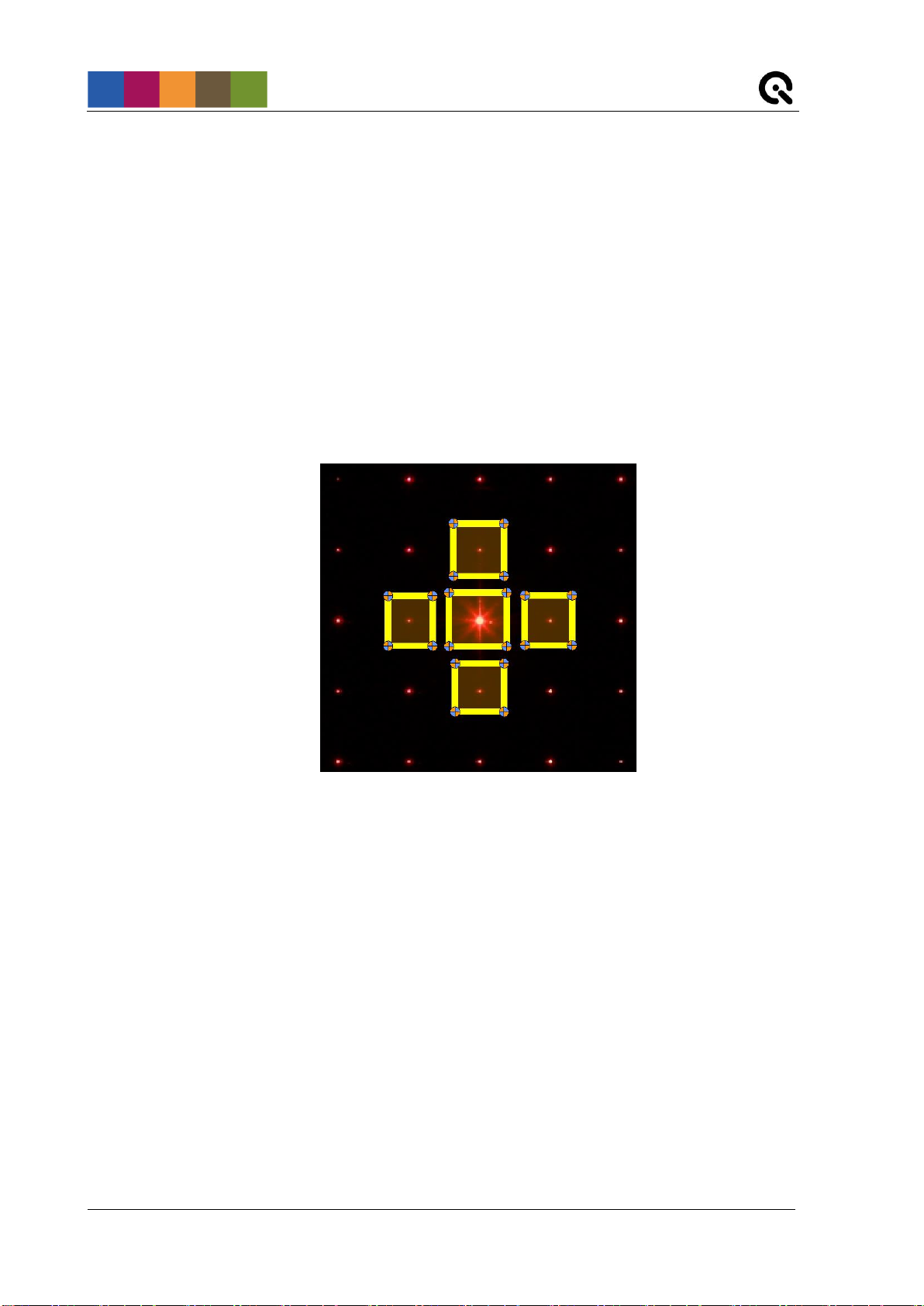
Image Engineering
Seite 11 von 15
For a successful analysis, it is not necessary to detect all of the points.
If auto-detection fails, you can do a manual ROI selection by setting the checkmark in the
“Detection & analysis” section (2). Five preset ROIs will then appear in the visualized image.
Size and position of these ROIs are adjustable by click&drag.
One ROI must be positioned on the 0th diffraction order (the brightest point in the center of the
grid). Adjust the ROI size so that it contains only one point.
The four remaining ROIs must be positioned on the four points closest to the 0th diffraction order,
i.e., the one above, below, to the left and to the right. These four ROIs may also only contain one
point. Furthermore, the individual ROIs should not overlap too much. See Figure 7 below for
reference.
•Analysis: After detection, the actual analysis can be performed. Click on the "Analyze" button in
the “Detection & analysis” section (2) to start the calibration. The progress bar (5) indicates when
the calibration is finished.
Depending on the number of points to be detected, the time needed for calibration may vary
slightly.
•Calibration results: the results will be listed unter the “Result table” tab in the “Image” section
(4). Please find an explanation of the values in chapter 4.2 of this manual. The RMSE of the
calibration is also included in the result table. If needed, you can clear the result table by clicking
“clear table”.
Under the tab “Distortion curve” you also get a graphical visualization of the determined distortion
of the camera (Geometric Distortion vs. Field).
Figure 7: Manual point detection

Image Engineering
Seite 12 von 15
Saving results
You have the option to either save your results to an XML or CSV type file. If you have analyzed multiple
images, select the one of which you would like to save the results from the list in the “Image data” section.
Then click File →Save result →Save XML or Save CSV →navigate to the desired location →click Save
Logging
The logging browser displays logging data for each action in the “Logging” section of the user interface. If
errors occur this can be helpful. The software also has a status bar at the bottom, where error messages
from the API are displayed directly.
Quit
To exit the software, click File → Quit (ctrl+q) or simply close the window.
TRADEMARK AND COPYRIGHT
Trademarks
Windows is a registered trademark of Microsoft Corp.,
Copyright Information
See separate Terms and Conditions document.

Image Engineering
Seite 13 von 15
5 ADDITIONAL INFORMATION
Disposal instructions
After the service life of GEOCAL, it must be disposed properly. Electrical and electromechanical
components are included in GEOCAL. Observe all national regulations. Make sure that GEOCAL cannot
be used by third parties after disposing of it.
Contact Image Engineering if assistance for disposal is required.
Image Engineering
Seite 14 von 15
6 DATA SHEET
Overview
Product name
GEOCAL
Principle
DOE-based geometric calibration of digital cameras
Features
6.2.1 [Hardware] Integrating sphere, Mount
Diffractive Optical
Element (DOE)
Generates a very evenly distributed point grid of 71x71 points
(continued by higher diffraction orders), virtually originating from infinity
Output window
Usable aperture: Ø 75 mm (camera lens needs to have an equal or smaller diameter)
Usable FoV
Approx. 30 – 120° (more extreme values need to be tested)
Dimensions (l x w x h)
ca. 550 mm x 144 mm x 162 mm
6.2.2 Illumination (CAUTION: DO NOT LOOK DIRECTLY INTO THE LIGHT SOURCE!)
Light source
Frequency-stabilized diode laser
Wavelength
633 nm
Output power
5 mW
Laser Class (diode only)
3B
Laser Class (GEOCAL)
1M (expanded laser beam)
6.2.3 Software
System requirements
PC with Windows 7 operating system (or higher)
USB port
Functions
•Load multiple images
•View selected image
•Perform calibration
•Overlay detected point grid
•Distortion visualization (graph)
•Export results (CSV and XML)
Output data
Camera intrinsic and extrinsic data, the orientation of DOE
API (C++)
Available as a separate option

Image Engineering
Seite 15 von 15
General description hardware
Power supply / consumption
25W 5V/5A
Ports
USB type b
Weight
Approx. 4.5 kg
Dimensions (l x w x h)
ca. 550 mm x 144 mm x 162 mm
Operating conditions
0-50°C
Requirements on the device under test (DUT)
Max. dimensions
Max. diameter of the camera lens: 75 mm
Usable FoV
Approx. 30 – 120° (more extreme values need to be tested)
Other manuals for GEOCAL
2
Table of contents
Other Image Engineering Test Equipment manuals


Popular Test Equipment manuals by other brands

Rigol
Rigol DS1000Z-E Series Performance Verification Guide

Hakko Electronics
Hakko Electronics FG101B-03 instruction manual

IDEAL
IDEAL 61-795 instruction manual

Airmar
Airmar TDT1000 quick start guide

Soundbyte Solutions
Soundbyte Solutions Parrotplus instructions

Sun Microsystems
Sun Microsystems Storedge A7000 Reference manual


