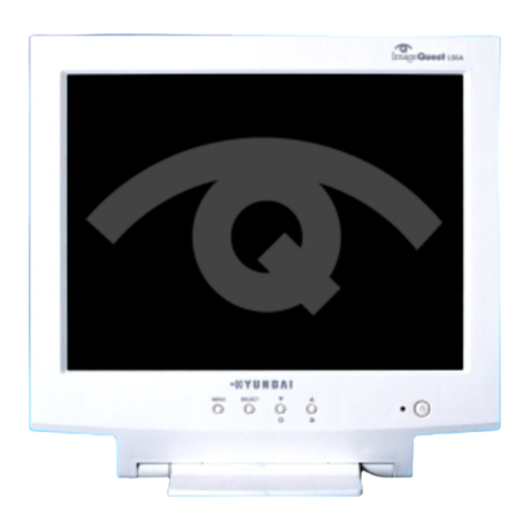
ImageQuest L80A Operating manual

Multiscanning Color Monitor
TECHNICAL SERVICE MANUAL
L80A

--1--
L80A Technical Service Manual
Safety Precaution
WARNING
Service should not be attempted by anyone unfamiliar with the necessary precautions on this monitor.
The followings are the necessary precautions to be observed before servicing.
1. When managing this monitor , cover with shield plate to avoid to scrach on LCD surface.
2. When replacing a chassis in the cabinet, always be certain that all the protective devices are
put back in place, such as nonmetallic control knobs, insulating covers, shields, isolation resistor
capacitor network etc.
3. Before returning the monitor to the customer, always perform an AC leakage current check
on the exposed metallic parts of the cabinet, such as signal connectors, terminals, screw heads,
metal overlays, control shafts etc, to be sure the monitor is safe to operate without danger of
electrical shock.
General Information
1. Description
This 18.1" LCD color display monitor is operated in R, G, B drive mode input.
2. Operating instructions
2-1. Front
Power Switch , Menu, Select, Down, Up, DPMS (Power) LED
2-2. Rear
Input connector (AC & Signal Cable & DVI Cable & Video Cable & USB Cable)
2-3. OSD Controls
H/V Position, Clock (H-Size),Clock Phase, Brightness, Contrast, Recall,Color Control, Preset
mode, Language, OSD Adjust , Auto Adjust
3. Electrical Characteristic
3-1. Power Supply
AC/DC - Input Voltage : 90V~264V
Input Current : 1A (Max)
Input Ferquency : 50 ~ 60Hz
- Output Voltage 12V/5V/10V
Output Current 2.5A/3A/1A
3-2. Video Input Signal
Level : 0.7 Vp-p analog signal(at 75 ohm termination to ground)
Polarity : Positive
3-3. Horizontal Synchronization Signal
Level : TTL High : 2.4V min
Low : 0.4V max
Polarity : - or +
Frequency : 31kHz ~ 80kHz
3-4. Vertical Synchronization Signal
Level : TTL High : 2.4V min
Low : 0.4V max
Polarity : - or +
Frequency : 56Hz ~ 87Hz

--2--
Control Description
Front View
Support Modes
(i) : Interlace Mode Timing
H Frequency
(kHz)
31.32
31.5
37.9
31.5
37.5
43.3
35.2
37.9
48.1
46.9
53.7
49.7
35.5
48.4
56.5
60.0
68.7
68.6
63.9
79.9
V Frequency
(Hz)
70.0
70.1
85.0
59.9
75.0
85.0
56.3
60.3
72.2
75.0
85.1
74.5
86.9
60.0
70.1
75.0
85.0
75.0
60.0
75.0
H
Polarity
0
0
0
0
0
0
1
1
1
1
1
0
1
0
0
1
1
1
1
1
V
Polarity
0
1
1
0
0
0
1
1
1
1
1
0
1
0
0
1
1
1
1
1
Pixe
Clock
25.056
28.322
35.500
25.175
31.500
36.000
36.000
40.000
50.000
49.500
56.250
57.283
44.900
65.000
75.000
78.750
94.500
100.000
108.000
135.000
NO
1
2
3
4
5
6
7
8
9
10
11
12
13
14
15
16
17
18
19
20
Resolution
640 x 400
720 x 400
720 x 400
640 x 480
640 x 480
640 x 480
800 x 600
800 x 600
800 x 600
800 x 600
800 x 600
832 x 624
1024 x 768 (i)
1024 x 768
1024 x 768
1024 x 768
1024 x 768
1152 X 870
1280 X 1024
1280 X 1024

--3--
L80A Technical Service Manual
Video Input Signal
Recommended signal are shown below
•Video Signal
Video level : 0 to 700mV
Polarity : positive
Video Input : RGB separated
Analog level
Sync input : H-Sync(TTL level)
V-Sync (TTL level)
•Waveform
Video input(R.G.B)
ACTIVE (T4)
Front Porch
(T5) Period (T1)
Sync Width (T2)
Back Porch (T3)
ACTIVE (T4)
Front Porch
(T5) Period (T1)
Sync Width (T2)
Back Porch (T3)
• H-Sync • V-Sync
0
1
2
3
4
251 252
253
254
255 700mV
0mV
• Signal: 256 level gray
scale
• Linear stepping:
(2.73mV ~ 256 Steps)

Video Input Terminal
1. Analog
A 15 Pin D-sub connector is used as the input signal connector
Pin and input signals are shown in the table below.
Pin Description
--4--
D-Sub miniature connector
1
2
3
45
10 9 8 7 6
11
12
13
14
15
SIGNAL
PIN NO.
3
2
1
5
4
6
7
8
9
10
11
12
13
14
SEPARATE SYNC/
DDC 1/2B
RED
GREEN
BLUE
GND
RETURN
RED GROUND
GREEN GROUND
BLUE GROUND
N.C
LOGIC GROUND
GROUND
SDA
H-SYNC(TTL)
V-SYNC(VCLK)
15 SCL

--5--
L80A Technical Service Manual
Pin Description
2. Digital
24 Pin DVI-D Interface connector is used as the input signal connector Pin and input signal
are shown in the table below.
Digital-Only Receptacle Connector
8
7
6
5
43
12
10
9
17 18 19 20 21 22 23 24
16
1514
13
12
11
PIN NO.
3
2
1
5
4
6
7
8
9
10
11
12
SEPARATE SYNC/
DDC 1/2B
T.MD.S Data 2-
T.MD.S Data 2+
T.MD.S Data2/4 Shield
T.MD.S Data 4-
T.MD.S Data 4+
DDC Clock
DDC Data
No Connect
T.MD.S Data1-
T.MD.S Data1+
T.MD.S Data 1/3 Shield
T.MD.S Data 3-
PIN NO.
15
14
13
17
16
18
19
20
21
22
23
24
T.MD.S Data 3+
+5V Power
Ground(for +5V)
Hot Plug Detect
T.M.D.S Data 0-
T.M.D.S Data 0+
T.M.D.S Data 0/5 Shield
T.M.D.S Data 5-
T.M.D.S Data 5+
T.M.S.D Clock Shield
T.M.D.S Clock +
T.M.D.S Clock -
SEPARATE SYNC/
DDC 1/2B

--6--
Connecting with External Equipment
Cautions
Be sure to turn off the power of your computer before connecting the monitor.
15 pin D-sub cable
(Analog RGB)
DVI-D cable (Digital RGB)

--7--
L80A Technical Service Manual
Theory of Operation
1. DC/AC INVERTER
Input voltage : DC 12V
Input current : 2.0A(Max)
Output current : 6m Arms(TYP)
Frequency(switching) : 50KHz
Output power : 19.2W(TYP)
On/off control voltage : 5.0V
2. DPMS MODE
Reference to DPMS files
Status
on Pulse Pulse Active
Blank
Blank
No
Pulse
No
Pulse
Pulse
No
Pulse
Suspend
off
Signal Power
Consumption
-
Within3
Sec
Within 3
Sec
Recovery
Time
Green/Orange(about 0.5 sec)
Orange
LED
Indicator
Green
60W
Less Than 10W
Less Than 5W
H-Sync V-Sync Video

--8--
On Screen Controls & LED Indicator
The menu for screen setting adjustment is located in the OSD and can be viewed in one of five
languages
OSD feature andmain funcrions are as follows:
The OSD adjustments available to you are listed below.
BRIGHTNESS
Adjust the brightness of the screen.
CONTRAST
Adjust the contrast of the screen.
H-POSITION
Adjust the horizontal position of the entire screen image.
V-POSITION
Adjust the vertical position of the entire screen image.
CLOCK (WIDTH)
Adjust the horizontal size of the entire screen image.
CLOCK-PHASE
Adjust the noise of the screen image.
AUTO ADJUST
Adjust the shape of screen atomatically.

--9--
L80A Technical Service Manual
COLOR CONTROL
Color temperature affects the tint of the image. With lower color
temperatures the image turns reddish and with higher temperatures
bluish.
There are three color settings available: Mode 1(a cool white), Mode 2(a
warm white) or USER. With the USER setting you can set individual values for
red, green and blue.
INFORMATION
INFORMATION
Information shows the horizontal and vertical frequency of your
display unit. The Information menu lists modes which are preset at the
factory and modes which have been defined by user. It also shows
you the mode your display unit is currently operating in. You can set
the display mode (frequency and refresh rate) in Windows.
LANGUAGE
You can select the language in which adjustment menus are displayed.
The following languages are available: English, French, German,
Italian, Spanish, Swedish, Finnish, Danish, Portuguese and Japanese
or Korean.
OSD ADJUST
You can adjusts the OSD menu's horizontal or vertical position on the
screen. You can also adjust display time of the OSD menu from 5 to
50 seconds.
SCALING MODE
This menu is used to choose the desired image size(Input video scaling).
There are three video scaling modes available :
• One to One : Select this item to view the same size as the input signal.
• Full Screen : Select this item to view the extended screen to the full size
horizontally and vertically.
• Aspectratio : Select this item to view the extended screen by width to the
full size with the vertical screen extended by the ratio of
the input signal.

--10--
SOURCE SELECT
This menu is used to choose the desired input signal source.
There are four signal sources available :
• Analog RGB : 15 pin D-sub, Analog signal
• Digital RGB : 24 pin DVI-D, Digital signal
• S-Video : MINI DIN, Separate video signal
• Composite-Video : RCA Jack, Composite video signal
TEST PATTERN
Displays internal test pattern.
The Clock Phase may not be optimized when the input timing is not comply
with VESA standard timing. In order to get the optimized result of Auto
Adjust Function, it is recommended to display bright color image on the
entire screen before proceeding Auto Adjust Function.
!

--11--
L80A Technical Service Manual
Getting Fine Picture
Step 1. At first Display, a full screen, such as, Window's background or "H" character should be
achieved by using Editor (ex: Notepad. exe)
Step 2. Adjust the screen to the center of the Display(LCD), by using the top and bottom display
controls. (i.e.Using V-Position Adjust menu)
Step 3. Adjust the screen to the center of the Display(LCD), by using the right and left display controls.
(i.e.Using Clock and H-Position adjust menu)
Step 4. Adjust the Clock-phase until the "H" Character displays clear.
Step 5. Using the Contrast. Brightness, and Color Control menu, set the color to your preference.
Step 6. When you finish the adjustment, you can save your settings by pressing on the menu until the
OSD screen has disappeared.
Factory Setting & EEPROM Initialization Method
Factory Setting Method
- Connect the signal cable and power cable to the LCD monitor.
- Press Power switch with pressed MENU key.(Menu key + Power key).
- Then, a User can change the factory setting value in OSD menu.
- Save changed value and Turn off the power s/w.
- Turn on the power, adjust the screen.

Specification
--12--
LCD Module
SIZE 18.1” Viewable diagonal
Dot Pitch 0.2805mm
Contrast Ratio
Response Time
300 : 1(TYP)
Brightness 200 cd/m2(TYP)
27ms (TYP.)
Input Signal Analog R.G.B Signal / TMDS Signal
Connector 15 pin D-SUB Connector/Digital 24Pin DVI
SYNC H-Freq 31.0 kHz~80 kHz
V-Freq 56Hz ~ 87 Hz
Display Area
Color
359.04(H)X287.232(V)mm
16.777M
Recommand Resolution
Video Bandwidth
User Control
&
OSD Control
Contrast,Brightness,H-V Position, Clock, Clock Control
Color Control, Information, Language, OSD Adjust(Position,
Display Time), Auto Adjust, Test, Pattern, Source, Select,
Scaling Mode
Power Management VESA DPMS Standard
Plug & Play VESA DDC 1/2B
Safety &
Regulation
EMC
Ergomomi
Safety
FCC CLASS B , CE , VCCI
TCO’99
cULus, CE, TUV-GS, SEMKO, DEMKO, FIMKO, NEMKO
Temperature
30 to 80%(Non-condensing)
5 to 90%(Non-condensing)
packed
Humidity
Operating
Operating
Storage
Storage
5 to 35 °C
- 5 to 45 °C
Weight unpacked
Dimension(LXWXH mm)
* Specification is subject to change without notice for performance improvement.
10.5Kg
202X440X435mm
8.1Kg
1280X1024 @ 60Hz
54MHz (Max)

--13--
L80A Technical Service Manual
Critical Parts Specification
1. LCD Module
HT18E22-200 is a A-Si TFT active matrix color liquid crystal comprising amorphous silicon TFT
attached to each signal electrode, a driving circuit and a backlight.
a built-in backlight display area contains 1280X1024 pixels and can display
full color (16.7M colors)
Display area 359.04(H)X287.232(V)mm
Drive system A-Si TFT
Display color 16.7M Colors
Number of Pixel 1280X1024
Pixel arrangement RGB vertical strip
Pixel pitch 0.2805(H)X0.2805(V)mm
Weight 2.6Kg
Contrast ratio 300:1
Viewing angle
Horizontal: 80 degree , 80 degree
Vertical: 80 degree , 80 degree
Response time 27ms(max)
Luminance 200 cd/m2(TYP)
Signal system Digital RGB signals, Sync signals(H, V-Sync),
Dot clock(DCLK) , DE(Data Enable)
Supply voltage 3.3V/12V (Typ)
Backlight Edge light type: Four colt cathode fluorescent lamps
With in- verter
Power consumption 4.45W(TYP) without B/L

--14--
GENERAL DESCRIPTION
The AD9884A is a complete 8-bit 140 MSPS monolithic analog
interface optimized for capturing RGB graphics signals from
personal computers and workstations. Its 140 MSPS encode
rate capability and full-power analog bandwidth of 500 MHz
supports display resolutions of up to 1280×1024 (SXGA) at
75 Hz with sufficient input bandwidth to accurately acquire and
digitize each pixel.
To minimize system cost and power dissipation, the AD9884A
includes an internal +1.25 V reference, PLL to generate a pixel
clock from HSYNC, and programmable gain, offset and clamp
circuits. The user provides only a +3.3 V power supply, analog
input, and HSYNC signals. Three-state CMOS outputs may be
powered by a supply between 2.5 V and 3.3 V.
The AD9884A’s on-chip PLL generates a pixel clock from the
HSYNC input. Pixel clock output frequencies range from
FEATURES
140 MSPS Maximum Conversion Rate
500 MHz Analog Bandwidth
0.5 V to 1.0 V Analog Input Range
400 ps p-p PLL Clock Jitter
Power-Down Mode
3.3 V Power Supply
2.5 V to 3.3 V Three-State CMOS Outputs
Demultiplexed Output Ports
Data Clock Output Provided
Low Power: 570 mW Typical
Internal PLL Generates CLOCK from HSYNC
Serial Port Interface
Fully Programmable
Supports Alternate Pixel Sampling for Higher-
Resolution Applications
APPLICATIONS
RGB Graphics Processing
LCD Monitors and Projectors
Plasma Display Panels
Scan Converters
FUNCTIONAL BLOCK DIAGRAM
SDA SCL A0A1PWRDN
HSYNC
COAST
CLAMP
FILT
CKEXT REFIN
CKINV
REFOUT
8
A/D
CLAMP
RIN
GIN
BIN
8
A/D
CLAMP 8
8
A/D
CLAMP 8
REF
8
8
8
8
8
8
SOGIN
0.15V
2
AD9884A
CLOCK
GENERATOR
SOGOUT
DATACK
ROUTA
ROUTB
GOUTA
GOUTB
BOUTA
BOUTB
HSOUT
CONTROL
20 MHz to 140 MHz. PLL clock jitter is typically 400 ps p-p
relative to the input reference. When the COAST signal is pre-
sented, the PLL maintains its output frequency in the absence
of HSYNC. A 32-step sampling phase adjustment is provided.
Data, HSYNC and Data Clock output phase relationships are
always maintained. The PLL can be disabled and an external
clock input provided as the pixel clock.
A clamp signal is generated internally or may be provided by the
user through the CLAMP input pin. This device is fully pro-
grammable via a two-wire serial port.
Fabricated in an advanced CMOS process, the AD9884A is
provided in a space-saving 128-lead MQFP surface mount plas-
tic package and is specified over a 0°C to +70°C temperature
range.
MC68HC705BD7B
AD9884A

--15--
L80A Technical Service Manual
PIN CONFIGURATION
92
93
95
90
91
88
89
87
96
86
94
81
82
83
84
79
80
78
76
77
85
75
73
74
71
72
69
70
67
68
66
65
98
99
101
97
102
100
41
42
43
44
46
47
48
49
39
45
40
62
61
60
64
63
59
55
50
51
52
53
54
56
57
58
11
10
16
15
14
13
18
17
20
19
22
21
12
24
23
26
25
28
27
30
29
32
31
5
4
3
2
7
6
9
8
1
34
33
36
35
38
37
120
121
122
123
124
125
126
127
128
119
111
118
117
116
115
114
113
112
110
109
108
107
106
105
104
103
PIN 1
IDENTIFIER
TOP VIEW
PINS DOWN
(Not to Scale)
V
D
REFIN
REFOUT
PWRDN
V
D
GND
GND
GND
V
DD
GND
SOGOUT
HSOUT
DATACK
DATACK
V
DD
GND
D
R
A
0
D
R
A
1
D
R
A
2
D
R
A
3
HSYNC
COAST
GND
PV
D
CKEXT
FILT
NC
GND
PV
D
GND
PV
D
GND
GND
GND
V
DD
D
B
B
7
D
B
B
6
D
B
B
5
D
B
B
4
D
R
B
0
D
R
B
1
D
R
B
2
D
R
B
3
D
R
B
4
D
R
B
5
D
R
B
6
D
R
B
7
V
DD
GND
D
G
A
0
D
G
A
1
D
G
A
2
D
G
B
2
D
G
B
3
D
G
B
4
D
G
B
5
D
G
B
6
D
G
B
7
V
DD
GND
NC
NC
NC
V
D
GND
GND
R
AIN
V
D
GND
V
D
V
D
GND
GND
SOGIN
G
AIN
V
D
GND
V
D
V
D
GND
GND
B
AIN
V
D
GND
V
D
GND
CKINV
CLAMP
SDA
SCL
A
0
A
1
D
B
B
3
D
B
B
2
D
B
B
1
D
B
B
0
GND
V
DD
GND
D
B
A
0
D
B
A
1
D
R
A
4
D
R
A
5
D
R
A
6
D
R
A
7
V
DD
GND
D
G
A
3
D
G
A
4
D
G
A
5
D
G
A
6
D
G
A
7
V
DD
GND
D
G
B
0
D
G
B
1
AD9884A
PV
D
PV
D
GND
NC
NC
NC
D
B
A
2
D
B
A
3
D
B
A
4
D
B
A
5
D
B
A
6
D
B
A
7
NC = NO CONNECT

--16--
MULTISTANDARD VIDEO DECODER/SCALER
The KS0127B converts analog NTSC, PAL or SECAM
video in composite, S-video, or component format to
digitized component video. Output data can be selected for
CCIR 601 or square pixel sample rates in either YCbCr or
RGB formats. The digital video can be scaled down in both
the horizontal and vertical directions. The KS0127B also
decodes Intercast, Teletext, Closed Caption, and WSS data
with a built-in bit data slicer. Digitized CVBS data can be
output directly during VBI for external processing.
FEATURES
• Accepts NTSC-M/N/4.43, PAL-M/N/B/G/H/I/D/K/L and
SECAM formats with auto detection
• 6 analog inputs: 3 S-video, 6 composite, or 1 3-wire
YCbCr component video
• 2-line luma and chroma comb filters including
adaptive luma comb for NTSC
• Programmable luma bandwidth, contrast,
brightness, and edge enhancement
• Programmable chroma bandwidth, hue, and
saturation
• High quality horizontal and vertical down scaler
• Intercast, Teletext and Closed Caption decoding with
built-in bit slicer
• Direct output of digitized CVBS during VBI for
Intercast application
• Analog square pixel or CCIR 601 sample rates
• Output in 4:4:4, 4:2:2, or 4:1:1 YCbCr component, or
24-bit or 16-bit RGB formats with dithering
• YCbCr 4:2:2 output can be 8 or 16 bits wide with
embedded timing reference code support for 8-bit
mode
• Simultaneous scaled and non-scaled digital output
ports outputs for 8-bit mode.
• Direct access to scaler via bi-directional digital port.
• Programmable Gamma correction table
• Programmable timing signals
• Industry standard IIC interface
100 PQFP
ORDERING INFORMATION
Device Package Temperature Range
KS0127B 100 PQFP -20°~+70°C
APPLICATIONS
• Multimedia
• Digital Video
• Video Capture/Editing
RELATED PRODUCTS
• KS0119Q2 NTSC VIDEO ENCODER
• KS0123 MULTISTANDARD VIDEO ENCODER
• KS0125 MULTISTANDARD VIDEO ENCODER
• KS0122 MULTISTANDARD VIDEO DECODER
• KS0127 MULTISTANDARD VIDEO DECODER
MC68HC705BD7B
KS0127B

--17--
L80A Technical Service Manual
PIN ASSIGNMENT - 100 PQFP
50
49
48
47
46
45
44
43
42
41
40
39
38
37
36
35
34
33
32
31
80 79 78 77 76 75 74 73 72 71 70 69 68 67 66 65 64 63 62 60 59 58 57 56 55 54 53 52 51
12345678910 11 12 13 14 15 16 17 18 19 20 21 22 23 24 25 26 27 28 29 30
EHAV
VSS
XTALO
XTALI
VDDA1
RST
VDD3
VSS
VSS
OEN
EXV0
PID
CK
VSS
VDD
CK2
ODD
VS
SCH(PORTB)
HAV
C0
C1
C2
C3
C4
C5
C6
VSS
VSS
VDD3
VDD3
C7
Y0
Y1
Y2
Y3
KS0127B
81
82
83
84
85
86
87
88
89
90
91
92
93
94
95
96
VDDA
COMP2
TEST
VSS
AC2
VDDA
AC1
VSS
AC0
VDDA
AY2
VSS
AY1
VDDA
AY0
VSS
VRT
HS2(IIC)
SCLK
CCEN
CCDAT
SDAT
EXV7
AEX1
AEX0
EXV6
VDD3
VDD3
VSS
VSS
EXV5
Y4
Y5
Y6
TESTEN
PORTA
VDD
VSS
EXV3
EXV4
97
98
99
100NCP
NCP
VAV(OENC0)
EVAV(OENC1)
VDD3
HS1
NCP
NCP
NCP
NCP
NCP
NCP
NCP
NCP
NCP
NCP
VRB
NCP
NCP
Y7
EXV1
EXV2
NCP
NCP
61

--18--
FEATURES
•Seven erase blocks:
16KB/8K-word boot block (protected)
Two 8KB/4K-word parameter blocks
Four main memory blocks
•SmartVoltage Technology (SVT):
3.3V ±0.3V or 5V ±10% VCC
5V ±10% or 12V ±5% VPP
•Address access times:
60ns, 80ns at 5V VCC
90ns, 110ns at 3.3V VCC
•Selectable organizations:
262,144 x 16 or
524,288 x 8
•Industry-standard pinouts
•Inputs and outputs are fully TTL-compatible
•Automated write and erase algorithm
•Two-cycle WRITE/ERASE sequence
•Byte- or word-wide READ and WRITE
•TSOP packaging option
OPTIONS MARKING
•Timing (5V VCC/3.3V VCC)
60ns/90ns access -6
80ns/110ns access -8
•Boot Block Starting Address
Top (3FFFFH) T
Bottom (00000H) B
•Packages
Plastic SOP (600 mil) SG
Plastic 48-lead TSOP Type 1 (12mm x 20mm) WG
•Part Number Example: MT28F400B1SG-8 T
PIN ASSIGNMENT (Top View)
44-Pin SOP
(FA-1)
V
PP
WP#
A17
A7
A6
A5
A4
A3
A2
A1
A0
CE#
V
SS
OE#
DQ0
DQ8
DQ1
DQ9
DQ2
DQ10
DQ3
DQ11
RP#
WE#
A8
A9
A10
A11
A12
A13
A14
A15
A16
BYTE#
V
SS
DQ15/A-1
DQ7
DQ14
DQ6
DQ13
DQ5
DQ12
DQ4
V
CC
1
2
3
4
5
6
7
8
9
10
11
12
13
14
15
16
17
18
19
20
21
22
44
43
42
41
40
39
38
37
36
35
34
33
32
31
30
29
28
27
26
25
24
23
48-Pin TSOP Type I
(FB-2)
A15
A14
A13
A12
A11
A10
A9
A8
NC
NC
WE#
RP#
V
PP
WP#
NC
NC
A17
A7
A6
A5
A4
A3
A2
A1
A16
BYTE#
V
ss
DQ15/A-1
DQ7
DQ14
DQ6
DQ13
DQ5
DQ12
DQ4
V
cc
DQ11
DQ3
DQ10
DQ2
DQ9
DQ1
DQ8
DQ0
OE#
V
ss
CE#
A0
1
2
3
4
5
6
7
8
9
10
11
12
13
14
15
16
17
18
19
20
21
22
23
24
48
47
46
45
44
43
42
41
40
39
38
37
36
35
34
33
32
31
30
29
28
27
26
25
GENERAL DESCRIPTION
The MT28F400B1 is a nonvolatile, electrically block-
erasable (Flash), programmable read-only memory con-
taining 4,194,304 bits organized as 262,144 words by 16 bits
or524,288wordsby8bits.SmartVoltageTechnology(SVT)
providesindustry-standard, multi- orsingle-voltage,dual-
supply operation. Writing or erasing the device is done
witheithera5Vor12V VPP voltage,whileall operations are
performed with a 3.3V or 5V VCC. It is fabricated with
Micron’s advanced CMOS floating-gate process.
The MT28F400B1 is organized into seven separately
erasableblocks.Toensurethatcriticalfirmwareisprotected
from accidental erasure or overwrite, the MT28F400B1
featuresahardware-protectedbootblock.Writingorerasing
the boot block requires either applying a super-voltage to
theRP# pin ordriving WP#HIGH in addition to executing
thenormal WRITE orERASEsequences. This block may be
used to store code implemented in low-level system
recovery. The remaining blocks vary in density and are
written and erased with no additional security measures.
MC68HC705BD7B
MF28F400B1

--19--
L80A Technical Service Manual
48-PIN PLASTIC TSOP I (12mm x 20mm)
FB-2
NOTE: 1. All dimensions in inches (millimeters) MAX or typical where noted.
MIN
2. Package width and length do not include mold protrusion; allowable mold protrusion is .01” per side.
.047 (1.20) MAX
.005 (0.12)
.007 (0.18)
24
.006 (0.15)
.010 (0.25)
SEE DETAIL A
.0197 (0.50)
TYP 1
.780 (19.81)
.727 (18.47)
.721 (18.31)
.795 (20.19)
.475 (12.07)
.002 (0.05)
DETAIL A
.016 (0.40)
.024 (0.60)
.032 (0.80)
.008 (0.20)
.004 (0.10)
.469 (11.91)
25
.010 (0.25)
PLANE
GAGE
.010 (0.25)
48
PIN #1 INDEX
Table of contents
Other ImageQuest Monitor manuals
