Imagine APM-215 User manual

Revision: B
Delivering the Moment
Installaon and Operaon Manual
APM-215
1 RU Analog Audio Monitor with
Level Meters and Phase
February 2011
821075

Publicaon Informaon
© 2014 Imagine Communicaons Corp. Proprietary and Condenal.
Imagine Communicaons considers this document and its contents to be proprietary and condenal.
Except for making a reasonable number of copies for your own internal use, you may not reproduce this
publicaon, or any part thereof, in any form, by any method, for any purpose, or in any language other
than English without the wrien consent of Imagine Communicaons. All others uses are illegal.
This publicaon is designed to assist in the use of the product as it exists on the date of publicaon of this
manual, and may not reect the product at the current me or an unknown me in the future. This pub-
licaon does not in any way warrant descripon accuracy or guarantee the use for the product to which it
refers.
Imagine Communicaons reserves the right, without noce to make such changes in equipment, design,
specicaons, components, or documentaon as progress may warrant to improve the performance of the
product.
Trademarks
Microso® and Windows® are registered trademarks of Microso Corporaon. AMD and Operton are
trademarks of Advanced Micro Devices, Inc. Dolby Digital is a registered trademark of Dolby Laboratories.
Java is a trademark of Sun Microsystems, Inc. or its subsidiaries in the United States and other countries.
All other trademarks and trade names are the property of their respecve companies.
Contact Informaon
Imagine Communicaons has oce locaons around the world. For locaons and contact informaon see:
hp://www.imaginecommunicaons.com/contact us/
Support Contact Informaon
For support contact informaon see:
▪Support Contacts: hp://www.imaginecommunicaons.com/services/technical support/
▪eCustomer Portal: hp://support.imaginecommunicaons.com

APM-215
1 RU Analog Audio Monitor with
Level Meters and Phase
Installation and Operation Manual
Revision B
February 2011


iii
Copyright ©2011, Harris Corporation
Contents
Manual Information ...................................................................................................... 1
Purpose ..................................................................................................................... 1
Audience ................................................................................................................... 1
Revision History ......................................................................................................... 1
Writing Conventions .................................................................................................. 1
Obtaining Documents ................................................................................................ 2
Unpacking/Shipping Information ................................................................................ 2
Unpacking a Product ................................................................................................. 2
Product Servicing ....................................................................................................... 2
Returning a Product ................................................................................................... 2
Safety ............................................................................................................................. 3
Safety Terms and Symbols in this Manual .................................................................. 3
Terms and Symbols on the Product ............................................................................. 3
Embedded Software License Agreement .................................................................... 4
Restriction on Hazardous Substances (RoHS) Compliance ......................................... 4
Waste from Electrical and Electronic Equipment (WEEE) Compliance ...................... 5
Chapter 1 Introduction.............................................................................................................. 7
Overview ....................................................................................................................... 7
Description .................................................................................................................... 7
Application .................................................................................................................... 7
Features ......................................................................................................................... 7
Front Panel ..................................................................................................................... 8
Rear Panel Connectors .................................................................................................. 8
Technical Functional Overview .................................................................................... 9
Chapter 2 Installation............................................................................................................. 11
Safety Instructions ...................................................................................................... 11
Installation Recommendations .................................................................................. 12
Unpacking ............................................................................................................... 12
Heat Dissipation ...................................................................................................... 12
Rack Mounting ........................................................................................................ 12
Cable Connections .................................................................................................. 12
Power ...................................................................................................................... 12

Contents
iv
Copyright ©2011, Harris Corporation
Electrostatic Discharge (ESD) ....................................................................................12
Chapter 3 Operation..................................................................................................................13
Audio Amplifier/Speaker Configuration ....................................................................13
Audio Amplifiers ......................................................................................................13
Speaker Configuration .............................................................................................13
Front Panel Controls ....................................................................................................14
Rear Panel Connectors .................................................................................................15
Internal Switch Settings ..............................................................................................15
Level Meter DIP Switch Settings ................................................................................16
Meter Input Gain Calibration Settings ......................................................................16
Bar Graph Display Modes .........................................................................................16
Chapter 4 Specifications.........................................................................................................17
Specifications ...............................................................................................................17
Appendix A Pinouts.......................................................................................................................19
XLR-F for Balanced Analog Audio Input ....................................................................19
XLR-M for Analog Audio Output ................................................................................19
Audio In/Out 37-Pin, Male, D-Sub Connector ............................................................20
Index...........................................................................................................................21

1
Copyright © 2011, Harris Corporation
Preface
Manual Information
Purpose This manual provides information about APM-215.
Audience This manual is written for engineers and software developers who are responsible for third
party control of the APM-215.
Revision
History
Writing
Conventions This manual adheres to the following writing conventions.
Table P-1. Revision History of Manual
Edition Date Revision History
A January 2011 Initial release
B February 2011 Minor updates to content
Table P-2. Writing Conventions
Term or Convention Description
Bold Indicates dialog box, property sheet, field, button, check box,
list box, combo box, menu, submenu, window, list, and
selection names
Italics Indicates email addresses, names of books and publications,
and first instances of new terms and specialized words that
need emphasis
CAPS Indicates a specific key on the keyboard, such as ENTER, TAB,
CTRL, ALT, DELETE
Code Indicates variables or command-line entries, such as a DOS
entry or something you type into a field.
> Indicates the direction of navigation through a hierarchy of
menus and windows.

Preface
2
Copyright © 2011, Harris Corporation
Obtaining
Documents Product support documents can be viewed or downloaded from our website. Alternatively,
contact your Customer Service representative to request a document.
Unpacking/Shipping Information
Unpacking a
Product This product was carefully inspected, tested, and calibrated before shipment to ensure years
of stable and trouble-free service.
1Check equipment for any visible damage that may have occurred during transit.
2Confirm that you have received all items listed on the packing list.
3Contact your dealer if any item on the packing list is missing.
4Contact the carrier if any item is damaged.
5Remove all packaging material from the product and its associated components before you
install the unit.
Keep at least one set of original packaging, in the event that you need to return a product
for servicing.
Product
Servicing IconKey systems are not designed for field servicing. Except for certain designated options
as described in this manual, all hardware upgrades, modifications, or repairs require you to
return the product to the Customer Service center.
Returning a
Product In the unlikely event that your product fails to operate properly, please contact Customer
Service to obtain a Return Authorization (RA) number, then send the unit back for servicing.
Keep at least one set of original packaging in the event that a product needs to be returned
for service. If the original package is not available, you can supply your own packaging as
long as it meets the following criteria:
The packaging must be able to withstand the product’s weight.
The product must be held rigid within the packaging.
There must be at least 2 in. (5 cm) of space between the product and the container.
The corners of the product must be protected.
hyperlink Indicates a jump to another location within the electronic
document or elsewhere
Internet address Indicates a jump to a Web site or URL
Note: Indicates important information that helps to avoid and
troubleshoot problems
Table P-2. Writing Conventions (Continued)
Term or Convention Description

APM-215
Installation and Operation Manual 3
Copyright © 2011, Harris Corporation
Ship products back to us for servicing prepaid and, if possible, in the original packaging
material. If the product is still within the warranty period, we will return the product prepaid
after servicing.
Safety Carefully review all safety precautions to avoid injury and prevent damage to this product or
any products connected to it. If this product is rack-mountable, it should be mounted in an
appropriate rack using the rack-mounting positions and rear support guides provided. It is
recommended that each frame be connected to a separate electrical circuit for protection
against circuit overloading. If this product relies on forced air cooling, it is recommended
that all obstructions to the air flow be removed prior to mounting the frame in the rack.
If this product has a provision for external earth grounding, it is recommended that the
frame be grounded to earth via the protective earth ground on the rear panel.
IMPORTANT! Only qualified personnel should perform service procedures.
Safety Terms
and Symbols
in this
Manual
Terms and Symbols on the Product
DANGER: High voltage; indicates a personal injury hazard immediately accessible as
one reads the marking.
WARNING: Indicates a personal injury hazard not immediately accessible as one
reads the marking.
CAUTION: Indicates a hazard to property including the product or to take Attention
and refer to the manual.
Protective ground (earth) terminal.
Fuse. Replace with same type and rating of fuse.
Observe precautions for handling electrostatic sensitive devices.
WARNING
Statements identifying conditions or practices that may result in
personal injury or loss of life. High voltage is present.
CAUTION
Statements identifying conditions or practices that can result in
damage to the equipment or other property.

Preface
4
Copyright © 2011, Harris Corporation
Embedded
Software
License
Agreement
The software embedded in this product incorporates the VxWorks Run-Time Module, and
the following paragraphs are applicable. You are prohibited from:
acopying the Run-Time Module, except for archive purposes consistent with your archive
procedures;
btransferring the Run-Time Module to a third party apart from the product containing
the Run-Time Module;
cmodifying, decompiling, disassembling, reverse engineering or otherwise attempting to
derive the source code of the Run-Time Module;
dexporting the Run-Time Module or underlying technology in contravention of
applicable U.S. and foreign export laws and regulations; and
eusing the Run-Time Module other than in connection with operation of the product in
which it is embedded.
Any further distribution of the Run-Time Module is subject to the same restrictions set forth
herein. Wind River Systems, Inc. and its licensors are third party beneficiaries of the End User
License Agreement and the provisions related to the Run-Time Module are made expressly
for the benefit of, and are enforceable by, Wind River Systems, Inc. and its licensors.
The laws of the Province of Ontario shall govern this Agreement. Updated June, 2008.
Restriction on Hazardous Substances (RoHS) Compliance
Directive 2002/95/EC—commonly known as the European Union (EU) Restriction on
Hazardous Substances (RoHS)—sets limits on the use of certain substances found in
electrical and electronic equipment. The intent of this legislation is to reduce the amount of
hazardous chemicals that may leach out of landfill sites or otherwise contaminate the
environment during end-of-life recycling. The Directive, which took effect on July 1, 2006,
refers to the following hazardous substances:
Lead (Pb)
Mercury (Hg)
Cadmium (Cd)
Hexavalent Chromium (Cr-V1)
Polybrominated Biphenyls (PBB)
Polybrominated Diphenyl Ethers (PBDE)
According to this EU Directive, all products sold in the European Union will be fully
RoHS-compliant and “lead-free.” (See our website for more information.) Spare parts
supplied for the repair and upgrade of equipment sold before July 1, 2006 are exempt from
the legislation. Equipment that complies with the EU directive will be marked with a
RoHS-compliant emblem, as shown in Figure P-1.
Figure P-1 RoHS Compliance Emblem

APM-215
Installation and Operation Manual 5
Copyright © 2011, Harris Corporation
Waste from Electrical and Electronic Equipment (WEEE) Compliance
The European Union (EU) Directive 2002/96/EC on Waste from Electrical and Electronic
Equipment (WEEE) deals with the collection, treatment, recovery, and recycling of electrical
and electronic waste products. The objective of the WEEE Directive is to assign the
responsibility for the disposal of associated hazardous waste to either the producers or users
of these products. As of August 13, 2005, the producers or users of these products were
required to recycle electrical and electronic equipment at end of its useful life, and may not
dispose of the equipment in landfills or by using other unapproved methods. (Some EU
member states may have different deadlines.)
In accordance with this EU Directive, companies selling electric or electronic devices in the
EU will affix labels indicating that such products must be properly recycled. (See our website
for more information.) Contact your local sales representative for information on returning
these products for recycling. Equipment that complies with the EU directive will be marked
with a WEEE-compliant emblem, as shown in Figure P-2.
Figure P-2 WEEE Compliance Emblem

Preface
6
Copyright © 2011, Harris Corporation

7
Copyright ©2011, Harris Corporation
1Introduction
Overview The APM-215 audio monitor provides self-powered, full-fidelity stereo monitoring in the
smallest rack space possible.
Description The APM-215 contains four high performance transducers driven by three power amplifiers:
two amplifier/driver combinations handle midrange and high frequency information in
stereo, while the third center channel reproduces information below the 500 Hz crossover
point through dual woofers.
The APM-215 analog audio monitor comes equipped with stereo volume and balance
potentiometers, a power indication LED, and a headphone output. Output limiter circuits are
incorporated to protect the speakers, and extensive magnetic shielding allows placement
immediately adjacent to video monitors with no color impurities.
Application The APM-215 is ideally suited for use in VTR bays, mobile production vehicles,
teleconferencing installations, multimedia systems, satellite links and cable TV facilities, and
on-air radio studios. Designed and manufactured in the U.S., the APM-215 is backed by a
strong warranty and a satisfaction guaranteed return policy.
Features 98 dB SPL at two feet
Only one rack space high
Excellent high frequency response for positive detection of background whine and noise
Audible indication of phase/polarity problems
Thorough magnetic shielding for placement next to video monitors
Numerous control and input options
Quick and easy installation: simply slide in the rack and connect audio and AC power

Chapter 1
Introduction
8
Copyright ©2011, Harris Corporation
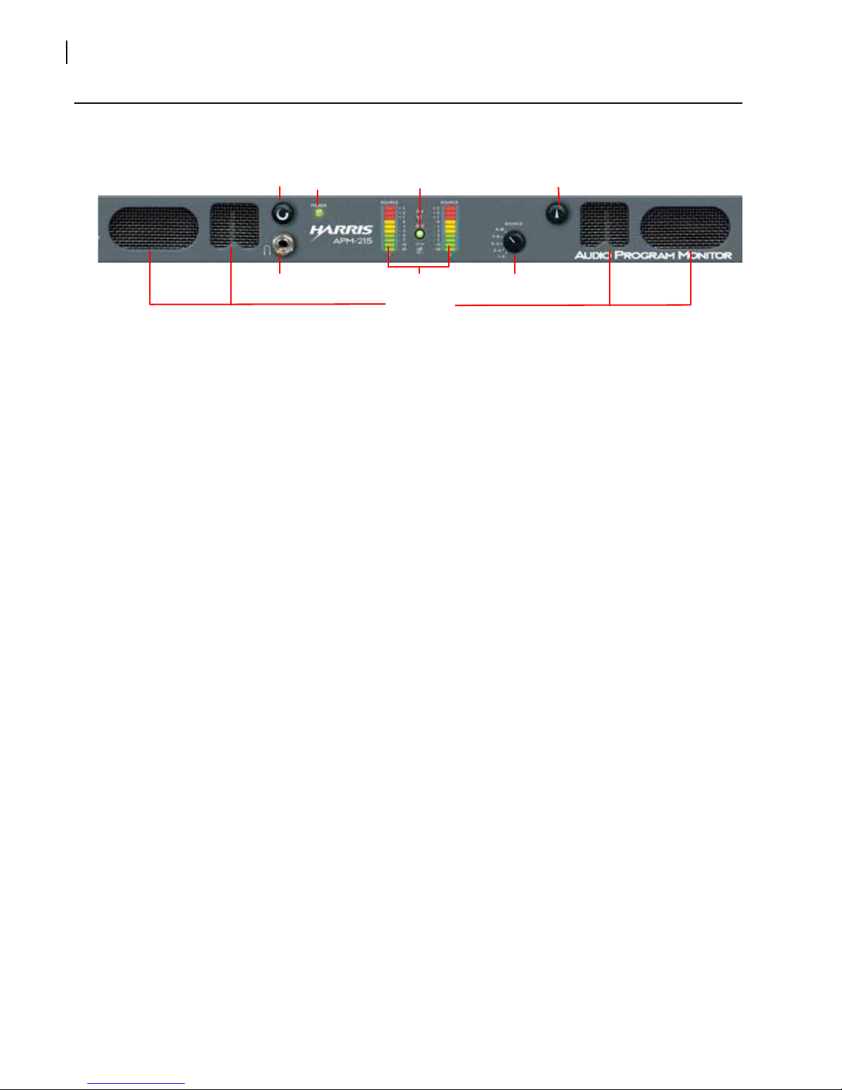
Front Panel
Figure 1-1 APM-215 Front Panel
Rear Panel Connectors
Figure 1-2 APM-215 Rear PanelInternal Switch Settings
Speakers
Headphones Level Meters
Volume BalancePower Phase
Source Select
Power Selected Analog
Out (Left & Right
Analog Audio Inputs
(Left & Right)

APM-215
Installation and Operation Manual 9
Copyright ©2011, Harris Corporation
Technical Functional Overview
Figure 1-3 illustrates the overall functionality of the APM-215 monitor.
Figure 1-3 APM-215 Block Diagram
10-Segment
Level Meters
Left
Speaker
Stereo Analog
Amplifier
Volume Balance
Woofer
Speaker
Phase Indication
Right
Speaker
Headphone
Woofer
Speaker
Right
Left
R
L
Stereo Output of
Selected Source
Switch
Switch
123 5
4
8
4
6
2
7
3
5
1
1: 1-2
2: 3-4
3: 5-6
4: 7-8
5: A-B
Right
Left
Source Pair Select
Balanced Analog Inputs
B
A
Balanced Analog
Inputs and
Loop-Through
Outputs

Chapter 1
Introduction
10
Copyright ©2011, Harris Corporation

11
Copyright ©2011, Harris Corporation
2Installation
Safety Instructions
Read, keep, and follow all of these instructions; heed all warnings.
Do not use this equipment near water.
Use only a dry cloth to clean the equipment.
Do not block any ventilation openings. Install only in accordance with the instructions in
Installation Recommendations on page 12.
Do not install near any heat source such as a radiator, heat register, amplifier, or stove.
Do not expose the equipment to rain or moisture.
Do not attempt to plug the unit into a two-blade outlet (with only two prongs of equal
width).
Note: .By design, these monitors will only plug into a three-prong outlet for your safety. If
the plug does not fit into your outlet, contact an electrician to replace the obsolete outlet.
Protect the power cord from being walked on or pinched, particularly at plug’s source
on the equipment and at the socket.
Use only the attachments/accessories specified by the manufacturer.
Unplug the equipment during lightning storms or when unused for long periods of
time.
Refer all servicing to qualified service personnel. Servicing will be required under all of
the following conditions:
The equipment has been damaged in any way, such as when the power-supply cord
or plug is damaged.
Liquid had been spilled or objects have fallen onto the equipment.
The equipment has been exposed to rain or moisture.
The equipment does not operate normally.
The equipment has been dropped.

Chapter 2
Installation
12
Copyright ©2011, Harris Corporation
Installation Recommendations
Unpacking Unpack the APM-215 Series monitor from the shipping container and inspect all
components for shipping damage. If you find any damage, notify the shipping carrier for
claims adjustments.
Compare the shipping box contents to the packing slip. Contact Harris’ customer support
personnel about any discrepancies. (Harris’ contact information in on the copyright page ii,
of this manual).
Heat
Dissipation The ambient temperature inside the mounting enclosure should not exceed 40°Celsius
(104°Fahrenheit). Adjacent devices can be rack mounted (or stacked) in proximity to the
unit if the above temperature is not exceeded. Allow a 1RU (1.75”/44.45mm) space above
and below the unit for air circulation.
Note: The heat generated by the power amplifiers, power supplies, and other components
is vented by slots in the side of the unit. Therefore, as a safety precaution, we advise you to
be sure to allow proper ventilation on both sides of the unit.
Rack
Mounting You should install the monitor into a standard 19" rack and requires a maximum of 3RU of
rack space (the 1RU unit, plus 1RU above and below).
Cable
Connections Harris recommends Belden 8281 or Belden 1694A cables for analog video signals and
Belden 9451 cables for analog audio signals.
Power Each unit comes with a standard mains power cord and connects an
A/C mains power source (65W, 100 to 240 VAC, 50/60Hz) to the IEC connector provided
on the rear panel of the unit.
Electrostatic
Discharge
(ESD)
As with most electronic equipment, static discharges can damage components within the
unit. Take precautions to ensure your installation environment is not subject to ESD.

13
Copyright ©2011, Harris Corporation
3Operation
Audio Amplifier/Speaker Configuration
Audio
Amplifiers The AMP-215 contains high performance speakers driven by three power amplifiers; two
amplifier/driver combinations handle midrange and high frequency information in the left
and right (stereo) speaker channels, while the third amplifier channel sums the left and right
channel information below the 500 Hz crossover point in the woofer (bass) speakers. Note
that the woofer channel is not a dedicated LFE or center channel.
Speaker Configuration
The 1U rack size APM-215 is configured with two speakers (left and right) to reproduce mid-
and high-range audio frequencies (in stereo), but feature two woofer speakers to reproduce
the summed (combined) low-range audio frequencies from the left and right speaker input
channels. It should be noted that both woofer speakers, which are wired in series, are driven
from one woofer speaker channel, and are not stereo. See the simplified diagram below for
a block diagram of the APM-215 audio amplifier/speaker configuration.
Figure 3-1 Audio Amplifier/Speaker Configuration
Chapter 3
Operation
14
Copyright ©2011, Harris Corporation
Front Panel Controls
Figure 3-2 APM-215 Front Panel
Level Meters: The APM-215 features two, 10-segment, bar graph audio meters.
Source Select (5-Position Rotary Switch): This switch selects, from the multi-channel
inputs, a single stereo audio source (2 channels) for monitoring through the unit.
Phase (LEDs): These three LEDs indicate the instantaneous and average phase (polarity)
conditions between the sources) assigned to the left speaker channel and the source(s)
assigned to the right speaker channel. The larger LED labeled AVG indicates the
average phase condition between the left and right speaker channels. The two smaller
LEDs labeled + and - indicate the instantaneous phase relationships. Indication is as
follows:
The upper + LED glows (or blinks) green for in-phase signals.
The lower - LED glows (or blinks) amber for out-of-phase signals.
The large center AVG LED indicates the average phase condition by glowing
green for in-phase signals, or red for out-of-phase signals.
In general, observing the average LED alone is sufficient for proper phase monitoring.
While it is normal for stereo signals to contain some intermittent instantaneous
out-of-phase and in-phase conditions (+ and- LEDs), a steady red glow of the
average LED indicates an out-of-phase alarm condition.
Speakers: The APM-215 internal speaker system is comprised of two mid-range
tweeter speakers (left and right) and two woofer speakers (left and right). The two
mid-range speakers reproduce, in stereo, only the mid and high frequencies, while the
two woofer speakers monaurally reproduce the low frequencies.
Volume Control: This controls the loudness of the audio reproduced by the internal
speakers or connected headphone. Clock-wise rotation of this control increases the
loudness of the monitored audio.
Headphones: The headphone output monitors the same audio signals as monitored
through the internal speakers. However, when you plug in headphones, the internal
speakers will mute. This jack accepts a standard 1/4” phone type stereo plug.
Power LED: This LED glows green to indicate the monitor is connected to operational
mains power.
Audio Level Meters: Audio levels are visually displayed via
tri-color (red, amber, green) LED bar graph display level meters.
Balance Control: This pans the volume balance between the left and right speakers.
The balance control attenuates the signal from the source, so that the left and right
bass frequencies (summed together and reproduced in the woofer channel) will also
respond to the balance control.
Speakers
Headphones Level Meters
Volume Balance
Power Phase
Source Select
Table of contents
Popular Speakers System manuals by other brands


Atlantic Technology
Atlantic Technology Compact Theater High Performance Compact manual

AUSTRALIAN MONITOR
AUSTRALIAN MONITOR CINEMA LOUDSPEAKER SYSTEM brochure

Altec Lansing
Altec Lansing VS4621 manual

Toa
Toa F-2000WT Specifications

Bauhn
Bauhn ASBWS-0419 instruction manual

DAD
DAD ARK COLUMN Series user manual