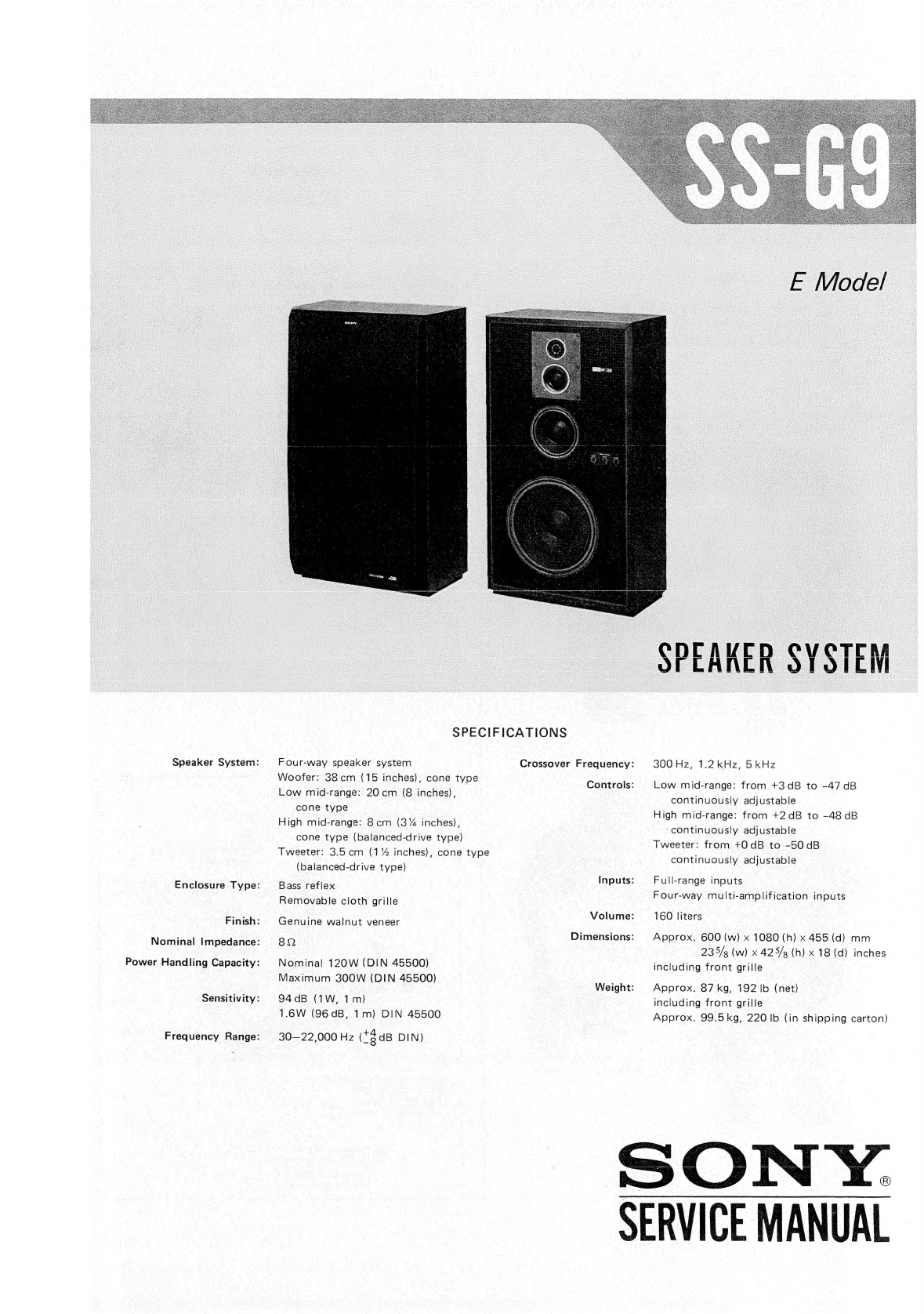
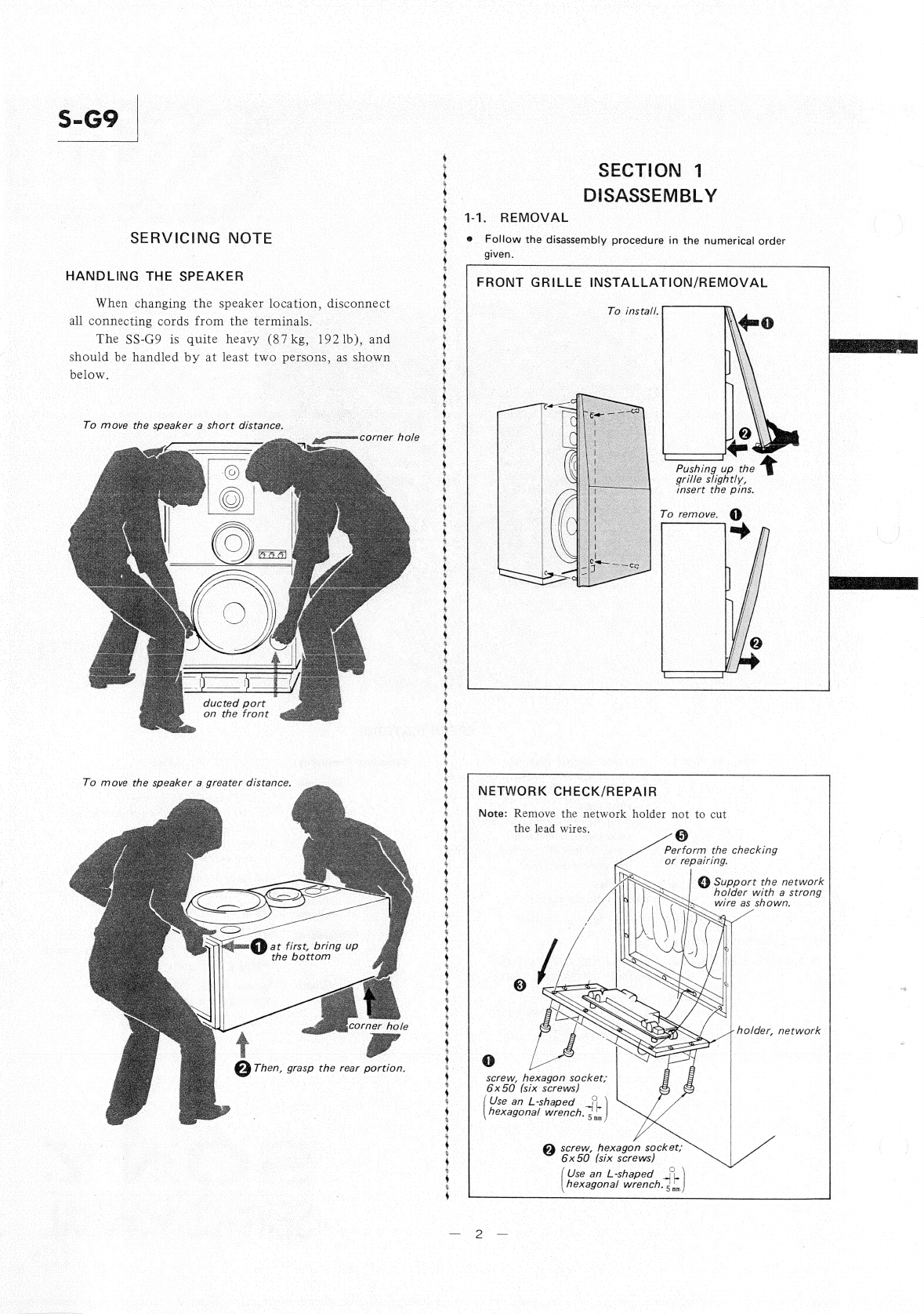
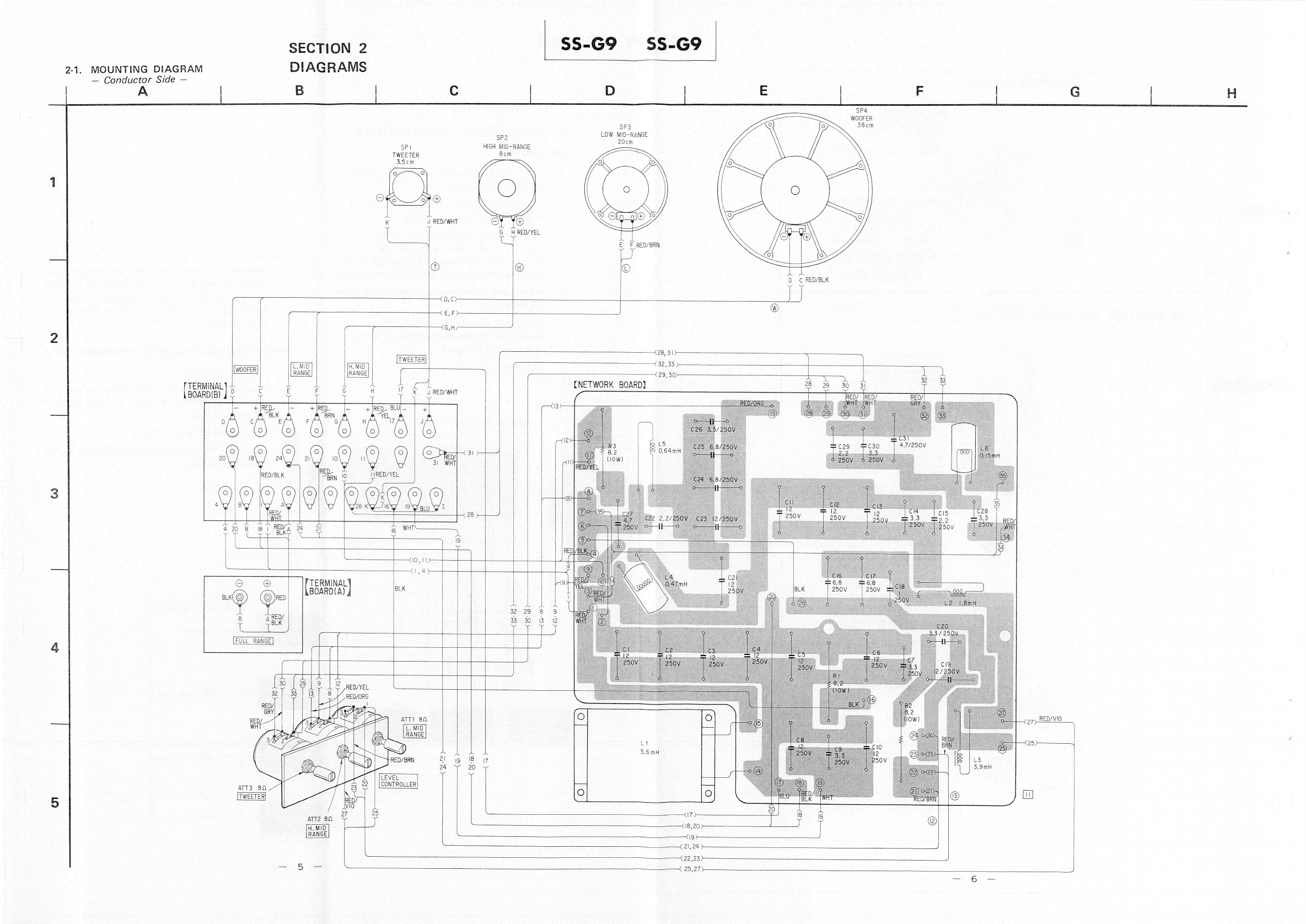
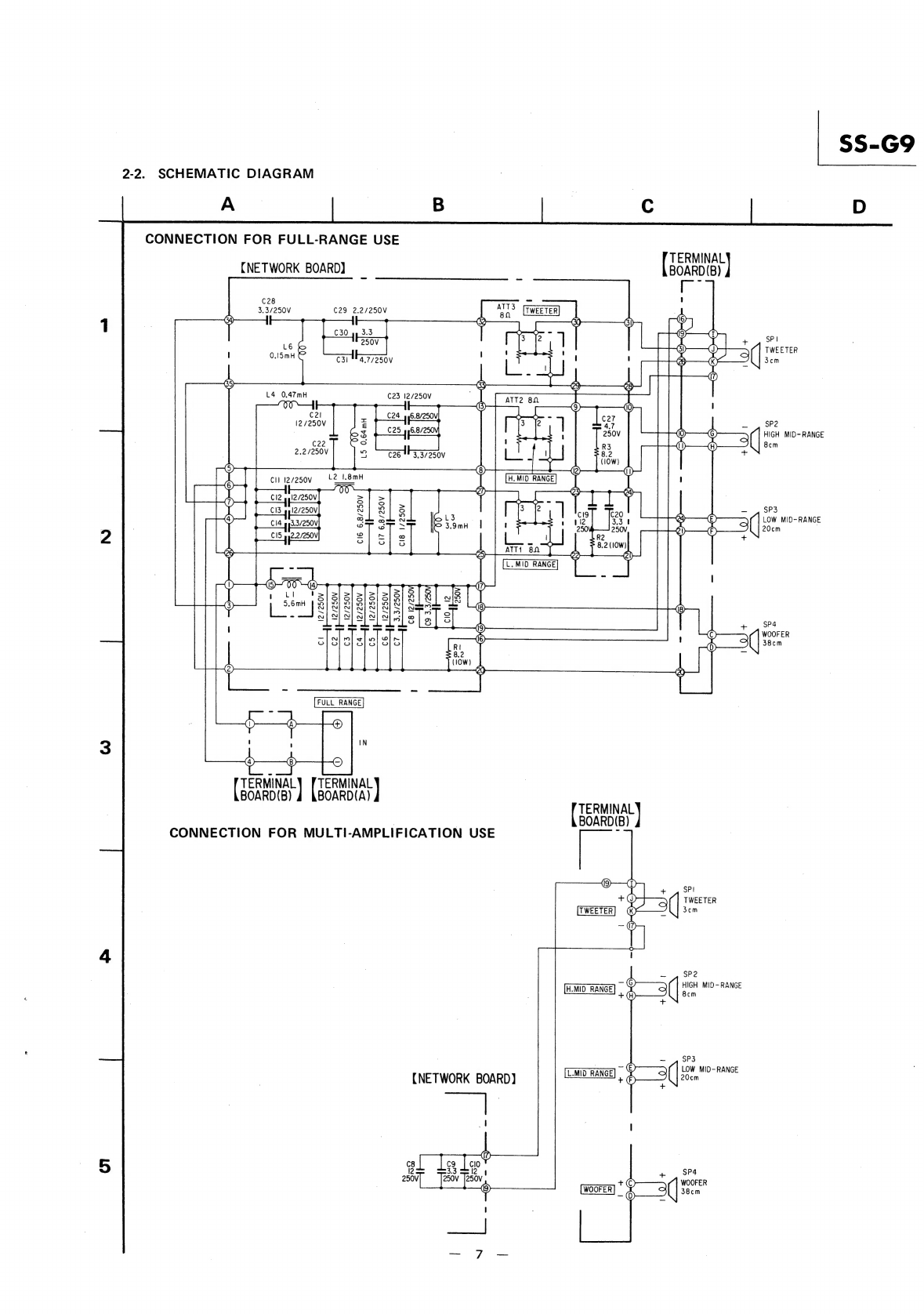
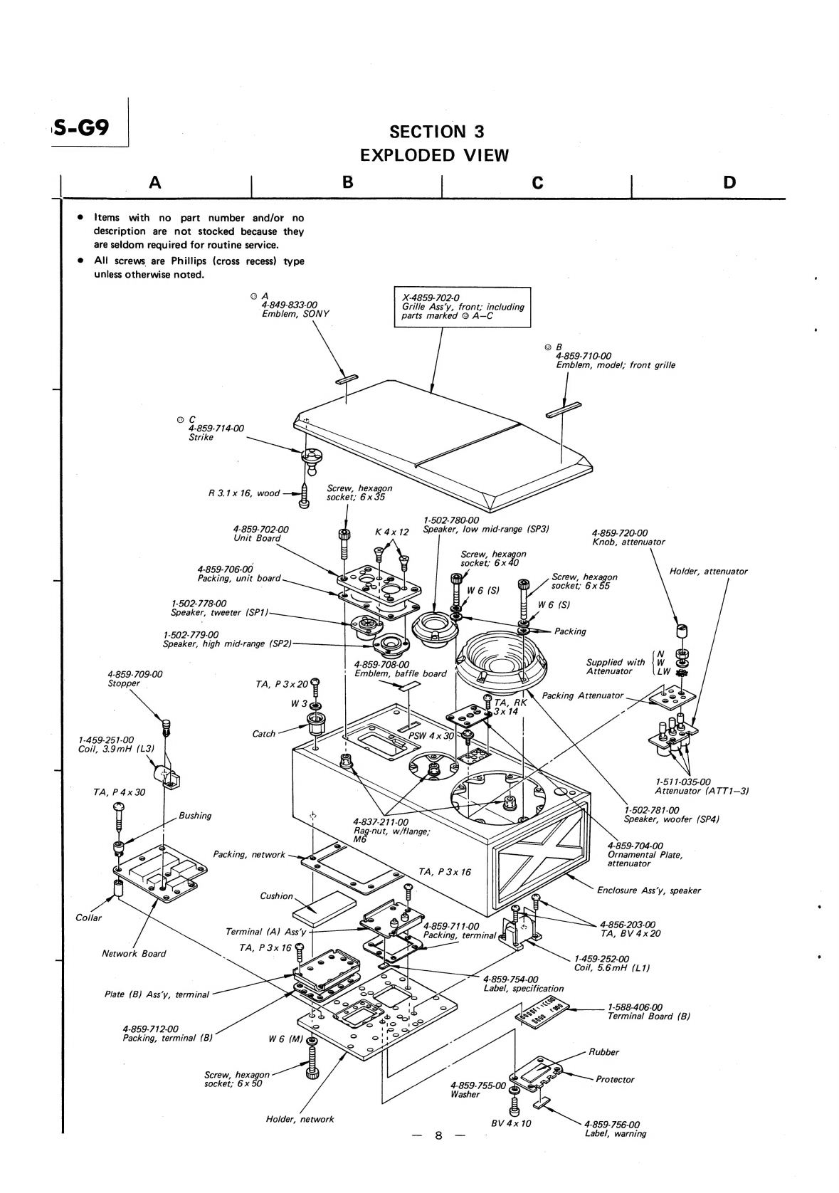
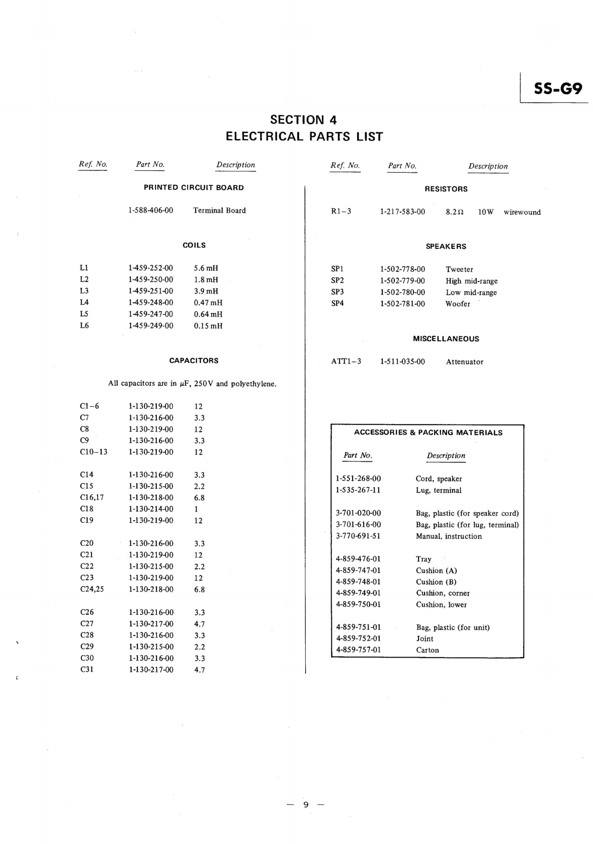
Sony SS-G9 User manual

Speaker
System:
Enclosure
Type:
Finish:
Nominal
Impedance:
Power
Handling
Capacity:
Sensitivity:
Frequency
Range:
*
SPECIFICATIONS
F
our-way
speaker
system
Crossover
Frequency:
Woofer:
38cm
(15
inches),
cone
type
Controls:
Low
mid-range:
20
cm
(8
inches),
cone
type
High
mid-range:
8cm
(3%
inches),
cone
type
(balanced-drive
type)
Tweeter:
3.5cm
(1%
inches),
cone
type
(balanced-drive
type)
Bass
reflex
EUG:
Removable
cloth
grille
Volume:
Genuine
walnut
veneer
82
Nominal
120W
(DIN
45500)
Maximum
300W
(DIN
45500)
94dB
(1W,
1m)
1.6W
(96
dB,
1m)
DIN
45500
Dimensions:
Weight:
30—22,000
Hz
(*$dB
DIN)
300
Hz,
1.2
kHz,
5kHz
Low
mid-range:
from
+3dB
to
-47
dB
continuously
adjustable
High
mid-range:
from
+2dB
to
-48
dB
-continuously
adjustable
.
Tweeter:
from
+0
dB
to
-50dB
continuously
adjustable
Full-range
inputs
Four-way
multi-amplification
inputs
160
liters
Approx.
600
(w)
x
1080
(h)
x
455
(d)
mm
235/g
(w)
x
425/s
(h)
x
18
(d)
inches
including
front
grille
|
Approx.
87
kg,
192
Ib
(net)
including
front
grille
Approx.
99.5kg,
220
Ib
(in
shipping
carton)
SERVICE
MANUAL

S-G9
SERVICING
NOTE
HANDLING
THE
SPEAKER
When
changing
the
speaker
location,
disconnect
all
connecting
cords
from
the
terminals.
oe
The
SS-G9
is
quite
heavy
(87kg,
192
1b),
and
should
be
handled
by
at
least
two
persons,
as
shown
below.
ae
ee
To
move
the
speaker
a
short
distance.
“corner
hole
ducted
port
on
the
front
To
move
the
speaker
a
greater
distance.
at
first,
bring
up
the
bottom
corner
hole
Q
Then,
grasp
the
rear
portion.
Pi
IN
A
ARB
AN
AS
A
A
AN
AL
A
AN
SY
RH
Et
SH
SR
LS
AL
RA
MH
RE
Ra
RA:
A
RN
AT
RA
RN
Re
Rs
A
HN
SL
RA
AR
A
AB
AL
AE
A
A
DY
A
A
RA
AN
A
AE
AA
AA
RAN
A
Ae
A
A
RA
A
RB
RN
AA
A
RB
A
A
A
A
I
I
SECTION
1
DISASSEMBLY
1-1.
REMOVAL
@
Follow
the
disassembly
procedure
in
the
numerical
order
given.
FRONT
GRILLE
INSTALLATION/REMOVAL
To
install.
Pushing
up
the
&
grille
slightly,
insert
the
pins.
To
remove.
@
NETWORK
CHECK/REPAIR
Note:
Remove
the
network
holder
not
to
cut
the
lead
wires.
5)
Perform
the
checking
or
repairing.
@)
Support
the
network
|
holder
with
a
strong
(Cer
(77)
holder,
network
NZD
So
“2
Ss
RS
'S,
S;
a,
Ss
S
=F
@
screw,
hexagon
socket;
6x50
(six
screws)
Use
an
L-shaped
>
real
wrench.
7°
@
screw,
hexagon
socket;
6x50
(six
screws)
Use
an
L-shaped
'
hexagonal
wrenc

TWEETER
AND
HIGH
MID-RANGE
REMOVAL
tweeter
_
(Set
the
speaker
terminals
toward
the
bottom
of
the
enclosure.)
@
K
4x
12
(four
screws)
cut
portion
screw,
hexagon
socket;
6x35
(three
screws
Use
an
L-shaped
hexagonal
wrench
@
K
4x12
(four
screws)
@
screw,
hexagon
socket;
6x35
(three
screws)
O
Use
an
L-shaped
hexagonal
Wrench.
5
mm
@
high
mid-range
(Set
the
speaker
terminal
toward
the
cut
portion.)
“5
mm
|
LOW
MID-RANGE
AND
WOOFER
REMOVAL
low
mid-range
(Set
the
letters
“SONY”
@
on
the
speaker
toward
A
|
oe
the
bottom
of
the
crHormlsudre.]
)
screw,
hexagon
socket;
6x40
(four
screws)
Use
an
L-shaped
ae
hexagonal
wrench.
coe
(Set
the
letters
“SONY”
on
the
speaker
toward
the
bottom
of
the
enclosure.)
screw,
hexagon
socket;
6x55
(eight
screws)
Use
an
L-shaped
a
hexagonal
wrench.
5
wm
ATTENUATOR
REMOVAL
|
|
@
PSW
4x30
@
Remove
the
woofer.
(four
screws)
ornamental
plate,
attenuator
@
TA,
RK3x14
~
(four
screws)
@
attenuator
@
Loosen
the
set
screw
(M
3x3)
with
an
L-shaped
wrench
to
pull
out
the
knobs.
Note:
Install
the
three
knobs
as
shown
below.
Hh
4
@
3
0)
SS-G9
SS-G
1-2.
MULTI-AMPLIFICATION
SYSTEM
USE
CONNECTION
1.
Take
out
the
four
screws
on
the
protector
and
remove
the
protector.
: |
2.
Loosen
the
twenty
seven
terminal
screws
on
the
terminal
board
(B)
and
slide
it
up.
3.
Fasten
all
the
nineteen
screws,
other
than
the
eight
on
the
bottom
line,
firmly
and
evenly.
If
the
screws
are
loose,
the
switching
function
for
multi-amplification
will
not
work
correctly.
4.
Solder
two
of
the
supplied
lugs
to
the
end
of
the
driver
cord.
5.
Install
the
lugs
on
the
eight
terminals
of
the
bottom
line
which
are
the
inputs
of
each
driver
unit,
and
tighten
them.
6...
Replace:
the.
protector.
Switching
connection
in
full-range
use
(slide
down
the
board
(B)).
source
.
ae
<Qaunge
terminal
board
(B)
L.MID.
RANGE
©
WOOFER
H.MID..
RANGE
TWEETER
©)
Electronic
.
“Crossover.
“Preamp
a
Bw
Fs
ne
_
network
CAUTION
@®
Be
sure
to
supply
the
correct
multi-amplified
signals
to
each
driver.
If
this
precaution
is
not
observed,
the
tweeter
may
be
damaged
by
low
frequency
overload,
even
though
a
protective
capacitor
of:
30
UF:
-is.-installed:
in’
the
-tweeter
section.
®
Since
the
woofer
is
usually
lower
in
efficiency
and
level
than
other
drivers,
first
set
the
low
level
control
at
maximum
as
a
reference
level,
and
then
turn
up
the
low
mid-range,
high
mid-range
and
high
level
controls
in
that
order
to
equalize
the
driver
output.
|
RESTORING
FULL-RANGE
SYSTEM
OPERATION
as.
Switching
connection
in
multi-amp
use
(slide
up
the
board
(B)).
~-High-freq.
__
power
amp,
|
High
mid-freq
power
amp
power
amp
—
Ge
Low
mid-freq.
i
Low
mid-range
~“Low-freq.
|
power
amp
|
Remove
the
protector.
Loosen
all
the
twenty
seven
terminal
screws
and
remove
the
driver
cord
lugs.
Slide
the
terminal
board
(B)
down.
Fasten
all
the
screws
firmly.
Connect
the
speaker
cord
to
the
FULL
RANGE
input
terminals.
at
Protective
capacitor
KC
Tweeter
|
.
High
mid-range
|
|
Woofer
SS-G9
|

SECTION
2
|
§S-G9
S$S-G9
9-1.
MOUNTING
DIAGRAM
DIAGRAMS
eee
ee
|
:
—
Conductor
Side
—
sons
CERIO
aos
ese
:
:
as
,
ae
WOOFER
SP3
38cm
LOW
MID-RANGE
|
She
20cm
SP
|
HIGH
MID-RANGE
TWEETER
8cm
3.5m
K
J
RED/WHT
OY
Ve
|
GH
RED/YEL
EF
RED/BRN
|
te
:
TWEETER
:
lec
L.
MID
H.
MIO
,
|
—_
Ral
|
|
|
RANGE
RANGE
re
:
et
]
a
PIERMINALY
A
A
Ak
oe
|
:
Ss
7
C
E
F
G
H
7
ee
|
|
BOARD(B)
0
G
F
6
K
J
RED/WHT
yy
1
. |
-
2
O
ae
| | |
|
,
a
|
es
|
-
|
:
ig
24\
reno
fa
3\
-
ee
|
RED/BLK
EL
|
as
|
.
| |
:
:
peg
BYD
S
.
O
O
:
IS‘
Btu
Gt
}
NH
Es
hee
|
|
RED/
“>
WHT
3
40
8
BiRKa
4B
2
|
0g
14
TERMINAL
Bek
BOARD(A)
oes
|
RED/YEL
Wee
RED/ORG
ee
(27)
RED/VIO
L.MID
RANGE
(25)
=
)
RED/BRN
re
ae
22
|
[CONTROLLER
TWEETER
i
AV10
ga
27
29
atT2
80
H.
MID
RANGE
X
|
(22,23)
7
J
5
Les
Ey
on
ory

$S-G9
2-2.
SCHEMATIC
DIAGRAM
CONNECTION
FOR
FULL-RANGE
USE
TERMINAL
{NETWORK
BOARD)
pas
C28
AIT3
(=
ji
3.3/250V
C29
2.2/250V
BO
1
GA)
29
(6)
C30
4,
3.3
250V
SPI
L6
&
TWEETER
oem
C31
a7/250v
zm
85)
C23
12/250V
12/250V
SP2
HIGH
MID-RANGE
C22
8cm
2.2/250V
ee
mine
>
aa
re
SP3
(4)
©
LOW
MID-RANGE
o
20cm
™
2
=
(1)
:
=
LI
>}
>el>e>l>ef
el
ela
“
al]
Ss}
af
a]
a}
;
=
=
9
+
.
SP4
)
WOOFER
S|
8}
3)
3/8]
S/S
7
om
(Ee
8.
fens
eereniny
BOARD(B)
4
KBOARD(A)
TERMINAL)
BOARD(B)
CONNECTION
FOR
MULTI-AMPLIFICATION
USE
SP2
HIGH
MID-RANGE
8cm
H.MID
RANGE]
|
2
SP3
=(€)
tom
MID-RANGE
=
L.MID
RANGE
(NETWORK
BOARD]
[WOOFER]
*

18-69
a
SECTION
3
EXPLODED
VIEW
|
A
B
ee
°:
OD
@
Items
with
no
part
number
and/or
no
description
are
not
stocked
because
they
are
seldom
required
for
routine
service.
e@
All
screws
are
Phillips
(cross
recess)
type
unless
otherwise
noted.
X-4859-702-0
OA
4-849-833-00
Grille
Ass’y,
front;
including
Emblem,
SONY
parts
marked
©
A—C
©
B
4-859-710-00
Emblem,
model,
front
grille
Oc
4-859-714-00
Strike
ED
O)
s
Screw,
hexagon
R
3.1x
16,
wood
zl
socket;
6x
35
“A
1-502-780-00
K4x12
Speaker,
low
mid-range
(SP3)
4-859-720-00
Knob,
attenuator
4-859-702-00
Unit
Board
Screw,
hexagon
j
socket;
6x
40
4-859-706-00
Holder,
attenuator
Packing,
unit
board
Screw,
hexagon
socket;
6x
55
W
6
(S)
“we
(S)
1-502-778-00
Speaker,
tweeter
(SP1)
1-502-779-00
Packing
Speaker,
high
mid-range
(SP2)
iz:
an.
N
Supplied
with
W
Attenuator
4-859-709-00
Stopper
-
1-459-251-00
Coil,
3.9mH
(L3)
1-511-035-00
TA,
P4x
30
Attenuator
(ATT1—3)
1-502-781-00
Speaker,
woofer
(SP4)
4-859-704-00
Ornamental
Plate,
attenuator
Enclosure
Ass’y,
speaker
Gorar
4-856-203-00
TA,
BV
4x
20
Cushion
<s
Terminal
(A)
Ass’y
4-859-711-00
Packing,
terminal
@&
Network
Board
1-459-252-00
Coil,
5.6mH
(L171)
4-859-754-00
Label,
specification
Plate
(B)
Ass’y,
terminal
S
CS
1-588-406-00
Ss
mS
Terminal
Board
(B)
4-859-712-00
Packing,
terminal
(B)
Rubber
Screw,
hexagon
Protector
socket;
6x
50
fo
4-859-755-00
>
Washer
F
BV
4x10
aL
4-859-756-00
Label,
warning
Holder,
network

SECTION
4
ELECTRICAL
PARTS
LIST
Ref.
No.
Part
No.
Description
PRINTED
CIRCUIT
BOARD
1-588-406-00
Teiinalhoard
COILS
Li
1-459-252-00
5.6mH
L2
1-459-250-00
1.8
mH
L3
1-459-251-00
3.9
mH
L4
1-459-248-00
0.47mH
LS
1-459-247-00
0.64
mH
L6
1-459-249-00
0.15mH
CAPACITORS
All
capacitors
are
in
uF,
250V
and
polyethylene.
C1—6
1-130-219-00
12
C7
1-130-216-00
Fe
C8
1-130-219-00
12
C9
1-130-216-00
a
C10-13
1-130-219-00
12
C14
1-130-216-00
3.3
C15
1-130-215-00
2.2
C16,17
1-130-218-00
6.8
C18
1-130-214-00
1
C19
1-130-219-00
12
C20
-
1-130-216-00
3.3
C21
—
1-130-219-00
12
C22
1-130-215-00
29
C23
1-130-219-00
12
C24,25
1-130-218-00
6.8
C26
1-130-216-00
3.3
C37
1-130-217-00
4.7
C28
1-130-216-00
34
C29
1-130-215-00
vp)
C30
1-130-216-00
one
C31
1-130-217-00
4.7
ATT1—3
1-511-035-00
Attenuator
ACCESSORIES
&
PACKING
MATERIALS
Part
No.
Description
1-551-268-00
Cord,
speaker
1-535-267-11
Lug,
terminal
3-701-020-00
Bag,
plastic
(for
speaker
cord)
3-701-616-00
Bag,
plastic
(for
lug,
terminal)
3-770-691-51
Manual,
instruction
4-859-476-01
Tray
4-859-747-01
Cushion
(A)
4-859-748-01
Cushion
(B)
4-859-749-01
Cushion,
corner
4-859-750-01
Cushion,
lower
4-859-751-01
Bag,
plastic
(for
unit)
4-859-752-01
Joint
4-859-757-01
Carton
$S8-G9
Ref.
No.
Part
No.
Description
RESISTORS
R1-3
1-217-583-00
8.22
10W
wirewound
SPEAKERS
SP1
1-502-77
8-00
Tweeter
SP2
1-502-779-00
High
mid-range
SP3
1-502-780-00
Low
mid-range
SP4
1-502-781-00
Woofer
MISCELLANEOUS
Table of contents
Other Sony Speakers System manuals

Sony
Sony PMC-DR45 - Personal Component System User manual

Sony
Sony SS-CR300 User manual

Sony
Sony SS-CS310CR User manual

Sony
Sony SS-FCR4000 Installation instructions manual

Sony
Sony SS-GX555 User manual

Sony
Sony SRS-NWM10 User manual

Sony
Sony CX-LDB30 User manual

Sony
Sony SS-V230 User manual

Sony
Sony HT-A5000 User guide

Sony
Sony SRS-Z1 User manual

Sony
Sony SS-GN800 User manual

Sony
Sony HT-ST5 User manual

Sony
Sony SRS-D4100 Operating Instructions (primary... User manual

Sony
Sony SS-CR350 User manual

Sony
Sony SA-VE155 User manual

Sony
Sony SS-SP10A User manual

Sony
Sony HT-CT790 User manual

Sony
Sony SRS-RF930RK - Wireless Speaker Sys User manual

Sony
Sony MHC-S9D User manual

Sony
Sony MP3 Walkman User manual