Imaging Source DFK 33UX252 Product manual

DFK 33UX252
Technical Reference Manual

DFK 33UX252 Technical ReferenceManual 2
Table of Contents
1. Quick Facts 5
2. Dimensional Diagrams 7
2.1 DFK 33UX252 C-Mount with Tripod Adapter .............................................................. 7
2.2 DFK 33UX252 C-Mount without Tripod Adapter ........................................................ 8
2.3 DFK 33UX252 CS-Mount with Tripod Adapter ............................................................ 9
2.4 DFK 33UX252 CS-Mount without Tripod Adapter .................................................... 10
3. I/O Connector 11
3.1 12-pin I/O Connector ................................................................................................... 11
TRIGGER_IN ........................................................................................................... 123.1.1 STROBE_OUT ......................................................................................................... 123.1.2
4. Spectral Characteristics 13
4.1 IR-Cut Filter ................................................................................................................... 13
4.2 Spectral Sensitivity - IMX252LQR-C ............................................................................ 13
5. Camera Controls 14
5.1 Sensor Readout Control .............................................................................................. 14
Pixel Format ........................................................................................................... 145.1.1 8-Bit Bayer Raw ...................................................................................................................................... 155.1.1.1
16-Bit Bayer Raw .................................................................................................................................... 155.1.1.2
YUV 4:2:2 .................................................................................................................................................. 155.1.1.3
YUV 4:1:1 .................................................................................................................................................. 165.1.1.4
RGB24 ....................................................................................................................................................... 165.1.1.5
8-Bit Monochrome ................................................................................................................................. 165.1.1.6
Resolution .............................................................................................................. 165.1.2 Readout Modes ...................................................................................................... 175.1.3 Frame Rate ............................................................................................................. 185.1.4 Partial Scan Offset ................................................................................................. 205.1.5 Image Flipping ....................................................................................................... 215.1.6
5.2 Image Sensor Control .................................................................................................. 21
Exposure Time ....................................................................................................... 215.2.1 Gain ........................................................................................................................ 225.2.2 Black Level ............................................................................................................. 225.2.3
5.3 Automatic Exposure and Gain Control ...................................................................... 23
Auto Exposure ........................................................................................................ 235.3.1 Auto Gain ............................................................................................................... 235.3.2 Auto Reference Value ............................................................................................ 245.3.3 Highlight Reduction ............................................................................................... 245.3.4 Auto Exposure Limits ............................................................................................. 245.3.5 Auto Gain Limits .................................................................................................... 255.3.6
5.4 Trigger ........................................................................................................................... 26

DFK 33UX252 Technical ReferenceManual 3
Table of Contents
Trigger Mode ......................................................................................................... 265.4.1 Trigger Polarity ...................................................................................................... 265.4.2 Software Trigger .................................................................................................... 275.4.3 Trigger Exposure Mode .......................................................................................... 275.4.4 Trigger Burst Count ................................................................................................ 275.4.5 Trigger Source ........................................................................................................ 285.4.6 Trigger Overlap ...................................................................................................... 285.4.7 IMX Low-Latency Mode ......................................................................................... 285.4.8
5.5 Trigger Timing Parameters .......................................................................................... 29
Trigger Delay ......................................................................................................... 295.5.1 Trigger Debounce Time ......................................................................................... 305.5.2 Trigger Mask Time ................................................................................................. 305.5.3 Trigger Noise Suppression Time ............................................................................ 305.5.4
5.6 Digital I/O ..................................................................................................................... 31
General Purpose Input ........................................................................................... 315.6.1 General Purpose Output ........................................................................................ 315.6.2
5.7 Strobe ........................................................................................................................... 32
Strobe Enable ......................................................................................................... 325.7.1 Strobe Polarity ........................................................................................................ 325.7.2 Strobe Operation .................................................................................................... 335.7.3 Strobe Duration ...................................................................................................... 335.7.4 Strobe Delay ........................................................................................................... 345.7.5
5.8 White Balance .............................................................................................................. 34
Auto White Balance ............................................................................................... 345.8.1 White Balance Mode ............................................................................................. 355.8.2 Manual White Balance .......................................................................................... 355.8.3
5.9 Image Processing ......................................................................................................... 37
Gamma ................................................................................................................... 375.9.1 Lookup Table .......................................................................................................... 385.9.2
5.10 Color Processing ........................................................................................................... 39
Hue ......................................................................................................................... 395.10.1 Saturation ............................................................................................................... 405.10.2
5.11 Region of Interest for Auto Functions ....................................................................... 40
Auto Functions ROI Enable .................................................................................... 405.11.1 Auto Functions ROI Preset ..................................................................................... 405.11.2 Auto Functions ROI Custom Rectangle .................................................................. 415.11.3
5.12 User Sets ....................................................................................................................... 42
User Set Selector .................................................................................................... 425.12.1 Load User Set ......................................................................................................... 425.12.2 Save User Set ......................................................................................................... 435.12.3 Default User Set ..................................................................................................... 435.12.4
5.13 Multi-Frame Output Mode ......................................................................................... 43
Multi-Frame Output Mode Enable ......................................................................... 435.13.1

DFK 33UX252 Technical ReferenceManual 4
Table of Contents
Multi-Frame Output Mode Frame Count ............................................................... 445.13.2 Multi-Frame Output Mode Exposure Time ............................................................ 445.13.3 Multi-Frame Output Mode Custom Gain ............................................................... 455.13.4 Multi-Frame Output Mode Gain ............................................................................ 455.13.5
6. Revision History 46

DFK 33UX252 Technical ReferenceManual 5
Quick Facts
1 Quick Facts
General
Vision Standard
USB3 Vision
Dynamic Range
12 bit
Resolution
2048x1536
Frame Rate at Full Resolution
120
Pixel Formats
8-Bit Monochrome
8-Bit Bayer (RG)
16-Bit Bayer (RG)
RGB24
YUV 4:2:2
YUV 4:1:1
Optical Interface
IR-Cut filter
Yes
Sensor Type
Sony IMX252LQR-C
Shutter Type
Global
Sensor Format
1/1.8 inch
Pixel Size
3.45 µm
Lens Mount
C/CS
Electrical Interface
Interface
USB 3.0
Supply voltage
4.75 VDC to 5.25 VDC
Current consumption
approx 720 mA @ 5 VDC
I/O Connector
12-pin connector for trigger and strobe or
general purpose input/output
Mechanical Data
Dimensions
H: 29 mm, W: 29 mm, L: 43 mm
Mass
65 g

DFK 33UX252 Technical ReferenceManual 6
Quick Facts
Adjustments
Shutter
20 µs to 4 s
Gain
0 dB to 48 dB
Environmental
Temperature (operating)
-5 °C to 45 °C
Temperature (storage)
-20 °C to 60 °C
Humidity (operating)
20 % to 80 % (non-condensing)
Humidity (storage)
20 % to 95 % (non-condensing)

DFK 33UX252 Technical ReferenceManual 7
Dimensional Diagrams
2 Dimensional Diagrams
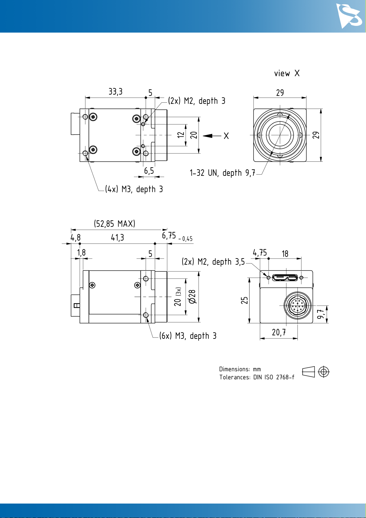
2.1 DFK 33UX252 C-Mount with Tripod Adapter
DFK 33UX252 Technical ReferenceManual 8
Dimensional Diagrams
2.2 DFK 33UX252 C-Mount without Tripod Adapter
DFK 33UX252 Technical ReferenceManual 9
Dimensional Diagrams
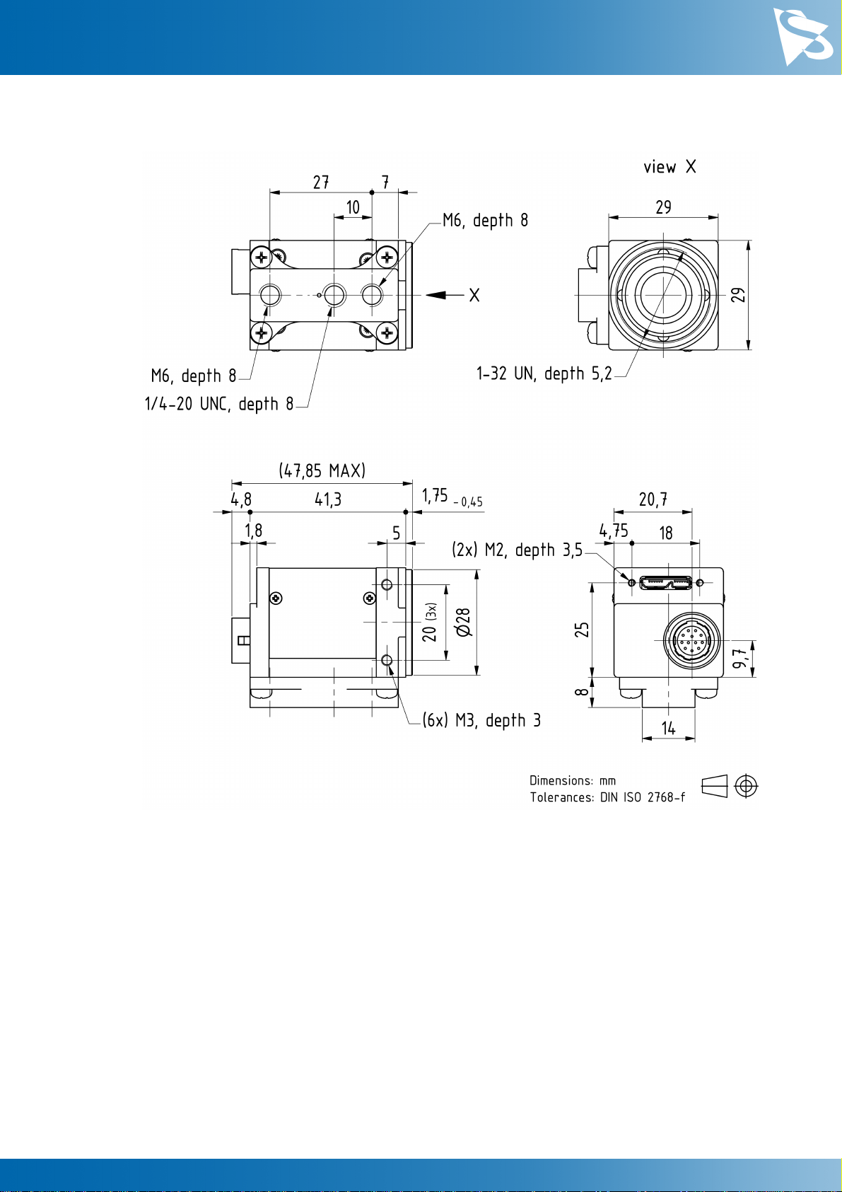
2.3 DFK 33UX252 CS-Mount with Tripod Adapter
DFK 33UX252 Technical ReferenceManual 10
Dimensional Diagrams
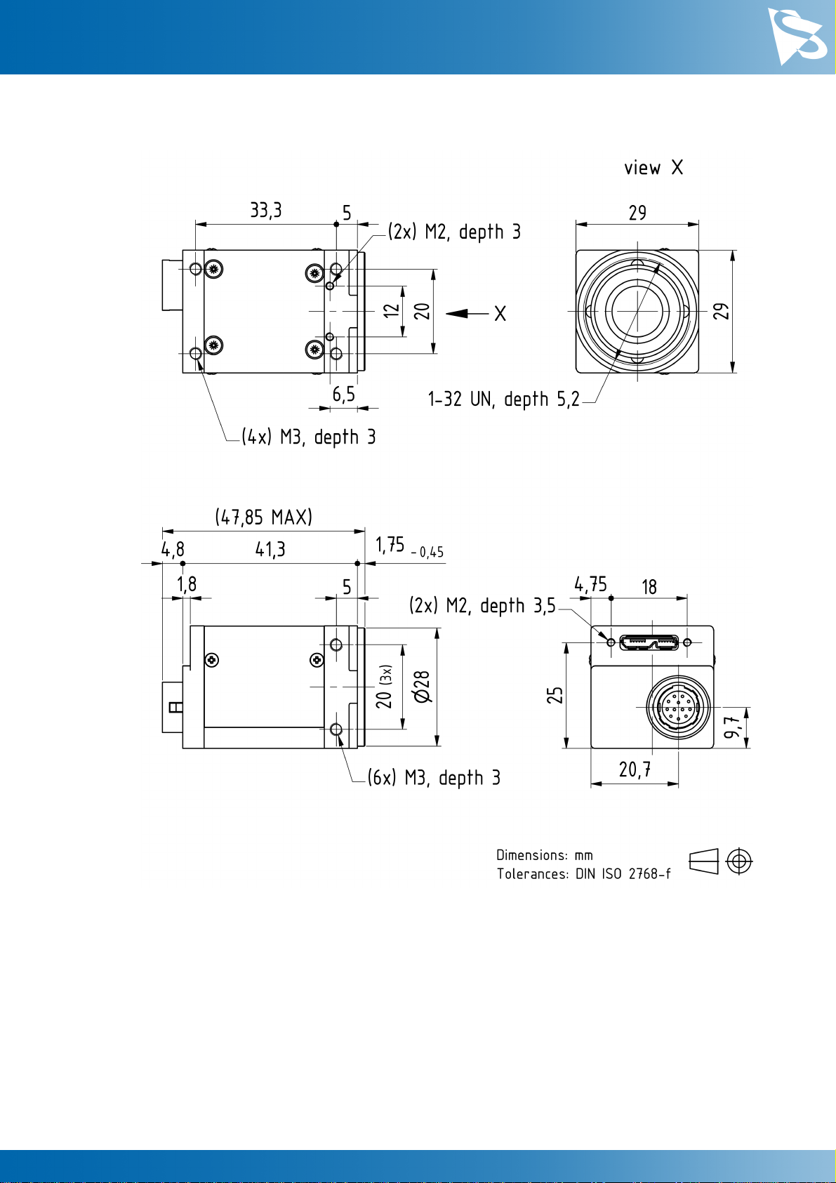
2.4 DFK 33UX252 CS-Mount without Tripod Adapter
DFK 33UX252 Technical ReferenceManual 11
I/O Connector
3 I/O Connector
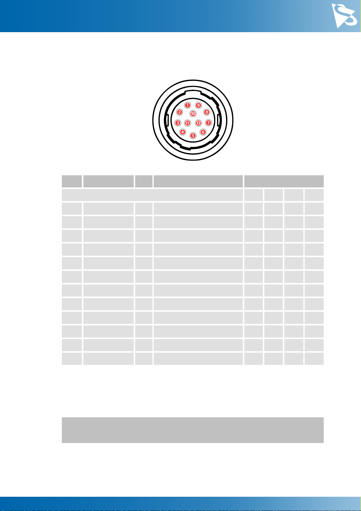
3.1 12-pin I/O Connector
Rear view of camera
Pin
Signal
I/O
Remarks
Characteristics
Min
Typ
Max
Unit
1
do not use
-
-
-
-
-
2
do not use
-
-
-
-
-
3
n.c.
-
-
-
-
-
4
n.c.
-
-
-
-
-
5
n.c.
-
-
-
-
-
6
n.c.
-
-
-
-
-
7
GND_I/O
G3
External Ground
-
-
-
-
8
n.c.
-
-
-
-
-
9
n.c.
-
-
-
-
-
10
STROBE_OUT
O3
Open drain
-
-
24.01
V
11
TRIGGER_IN (+)
I3
Optocoupler signal
3.32
-
24.02
V
12
TRIGGER_IN (-)
I3
Optocoupler ground
-
-
-
-
1max. 0.2A (ID) for open drain MOSFET!
2min. 3.5 mA driver strength required!
3G: Ground O: Output I: Input
The part number of this Hirose connector is HR10A10R-12P(73). To create an I/O
cable you need a Hirose connector HR10A-10P-12S(73).

DFK 33UX252 Technical ReferenceManual 12
I/O Connector
3.1.1 TRIGGER_IN
The TRIGGER_IN line can be used to synchronize the start of the exposure time with
external events. The Trigger section describes in detail how the image sensor's behavior
can be controlled.
The current input signal can also be read directly through the General Purpose Input
feature.
3.1.2 STROBE_OUT
The STROBE_OUT line's main usage is to indicate the integration time of the image
sensor which allows flashes, strobes or other light sources to be synchronized with
camera operation. The line's behavior can be controlled through the Strobe controls.
The output signal can also be directly controlled through the General Purpose Output
feature.
DFK 33UX252 Technical ReferenceManual 13
Spectral Characteristics
4 Spectral Characteristics
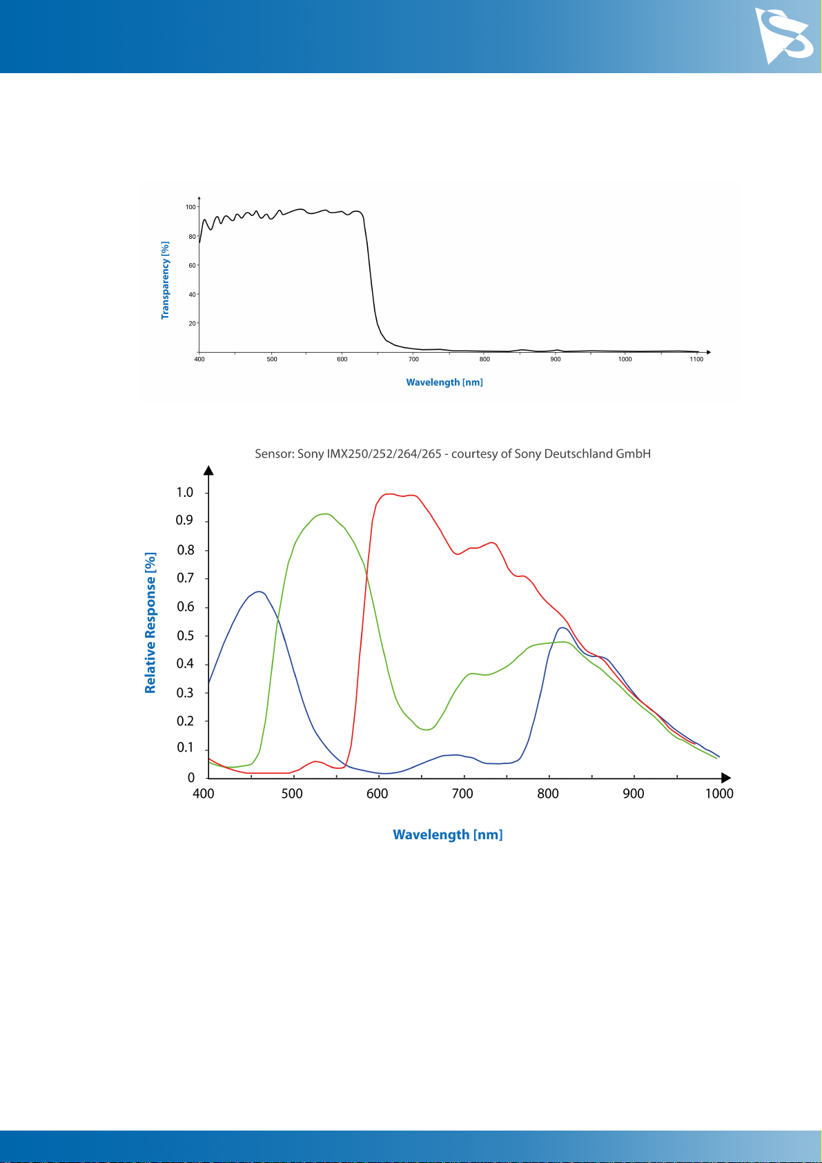
4.1 IR-Cut Filter
4.2 Spectral Sensitivity - IMX252LQR-C

DFK 33UX252 Technical ReferenceManual 14
Camera Controls
5 Camera Controls
This section describes the parameters available for the DFK 33UX252 camera.
The actual name of the parameter depends on the driver technology used to access the
camera. Parameter names are listed for the most common ways to access the cameras:
·
USB3 Vision (cross platform, via 3rd party driver)
·
UVC/V4L2 (on Linux, via uvcvideo)
·
IC Imaging Control (on Windows, via Device Driver for The Imaging Source USB 33U,
37U and 38U Cameras)
5.1 Sensor Readout Control
5.1.1 Pixel Format
The pixel format defines the data type of the pixels transmitted to the computer. The
bits per pixel needed for a particular pixel format influence the required bandwith.
The driver technology used to access the camera significantly impacts the way the pixel
format is controlled:
·
When using USB3 Vision, the pixel format is controlled through the PixelFormat
GenICam feature.
·
When using the uvcvideo driver on Linux, the pixel format is defied by video4linux2.
·
When using IC Imaging Control, the pixel format is part of the video format - a
parameter which combines pixel format, resolution and readout mode. For more
information, refer to the IC Imaging Control documentation sections on
VideoFormat and VideoFormatDesc.
The DFK 33UX252 color camera supports multiple pixel formats with variable bits-per-
pixel settings. The names of the pixel formats and the way to select them depends on
the driver used to control the camera. The following table contains a short overview of
all possible formats followed by a more detailed description.
Pixel Format
Bits Per Pixel
USB3 Vision
UVC
TIS UVC Driver
8-Bit Bayer
(RG)
8
BayerRG8
RGGB
RGB32, Y800
16-Bit Bayer
(RG)
16
BayerRG16
RG16
RGB64, Y16
YUV 4:2:2
16
YCbCr422_8
YUY2
YUY2
YUV 4:1:1 (a)
12
YCbCr411_8
YUV 4:1:1 (b)
12
YCbCr411_8_
CbYYCrYY
Y411
Y411
RGB24
24
BGR8
RGB24
RGB24
8-Bit
Monochrome
8
Mono8

DFK 33UX252 Technical ReferenceManual 15
Camera Controls
5.1.1.1 8-Bit Bayer Raw
This format transmits data using one byte for each pixel.
USB3 Vision drivers see this pixel format as one of the 8-bit bayer raw formats
(BayerGR8, BayerRG8, BayerGB8, BayerBG8).
UVC drivers see it with the FourCC GRBG, RGGB, GBRG or BA81.
The Device Driver for The Imaging Source USB 33U, 37U and 38U Cameras simplifies this
variety of possible pixel formats and offers two video formats instead: RGB32 and
Y800. The RGB32 format results from the driver's automatic debayering of the raw
image data, while the Y800 format contains the raw data which is reinterpreted as
monochrome.
5.1.1.2 16-Bit Bayer Raw
This format transmits data using 2 bytes for each pixel.
The sensor of the DFK 33UX252 camera is not able to provide 16-bit data output. The
pixel data is transmitted in the most significant bits. This allows application programs
to ignore the sensor-specific data type and to treat the data as if the sensor outputs 16
bits.
USB3 Vision drivers see this pixel format as one of the 16-bit packed bayer raw formats
(BayerGR16, BayerRG16, BayerGB16, BayerBG16).
UVC drivers see it with the FourCC GR16, RG16, GB16 or BA16.
The Device Driver for The Imaging Source USB 33U, 37U and 38U Cameras simplifies this
variety of possible pixel formats and offers two video formats instead: RGB64 and Y16.
The RGB64 format results from the driver's automatic debayering the raw image data,
while the Y16 format contains the raw data which is reinterpreted as monochrome.
5.1.1.3 YUV 4:2:2
This format transmits an 8-bit luminance value for every pixel and a pair of
chrominance values for every two pixels.
The camera converts the raw pixel data from the sensor to YUV 4:2:2. Since YUV 4:2:2
averages to 2 bytes per pixel, the YUV 4:2:2 pixel format requires two times the
bandwidth of the 8-bit raw format, thus reducing the maximum possible frame rate.
USB3 Vision drivers see this pixel format as YCbCr422_8.
UVC drivers see it with the FourCC YUY2.
The Device Driver for The Imaging Source USB 33U, 37U and 38U Cameras offers this
pixel format as the YUY2 video format.

DFK 33UX252 Technical ReferenceManual 16
Camera Controls
5.1.1.4 YUV 4:1:1
This format transmits an 8-bit luminance value for every pixel and a pair of
chrominance values for every four pixels.
The two YUV 4:1:1 pixel formats only differ in their byte order.
The camera converts the raw pixel data from the sensor to YUV 4:2:2. Since YUV 4:2:2
averages to 1.5 bytes per pixel, the YUV 4:2:2 pixel format requires two 50% more
bandwidth than the 8-bit raw format, thus reducing the maximum possible frame rate.
USB3 Vision drivers see this pixel format as YCbCr411_8 and
YCbCr411_8_CbYYCrYY.
UVC drivers see it with the FourCC Y411.
The Device Driver for The Imaging Source USB 33U, 37U and 38U Cameras offers this
pixel format as the Y411 video format.
5.1.1.5 RGB24
The camera converts the raw pixel data from the sensor to RGB24. Since RGB24 uses 3
bytes to store 1 pixel, the RGB24 pixel format requires three times the bandwidth of the
8-bit raw format, thus reducing the maximum possible frame rate.
USB3 Vision drivers enumerate this pixel format as BGR8.
UVC drivers see it with the FourCC RGB24.
The Device Driver for The Imaging Source USB 33U, 37U and 38U Cameras enumerates
this pixel format as the RGB24 video format.
5.1.1.6 8-Bit Monochrome
The camera generates the pixel data by debayering the raw pixel data and transmitting
only the luminance information.
USB3 Vision drivers enumerate this pixel format as Mono8.
UVC drivers do not have access to this format.
5.1.2 Resolution
The DFK 33UX252 allows the user to specify which rectangular region of the image
sensor to read out during camera operation. The size of this rectangle determines the
number of pixels that have to be transferred for each frame and has a significant
influence on the required USB bandwidth.
Lowering the resolution also often allows the image sensor to operate at a higher frame
rate. Changes in the vertical resolution have more effect on the maximum frame rate
than changes in the horizontal direction.
The way the resolution is controlled varies greatly between the driver technology used
to access the camera:

DFK 33UX252 Technical ReferenceManual 17
Camera Controls
·
When using USB3 Vision, the resolution is controlled through the GenICam features
Width and Height.
·
When using the uvcvideo on Linux, the resolution is selected from a list of fixed
formats. Dynamic frame sizes are not available.
·
When using IC Imaging Control, the resolution is part of the video format, a parameter
that combines pixel format, resolution and readout mode. For more information, refer
to the IC Imaging Control documentation sections on VideoFormat and
VideoFormatDesc.
Parameter
Horizontal Resolution
Minimum
256
Maximum
2048
USB3 Vision: GenICam
Width
Parameter
Vertical Resolution
Minimum
4
Maximum
1536
USB3 Vision: GenICam
Height
5.1.3 Readout Modes
The DFK 33UX252 camera offers different sensor readout modes.
By default, the camera outputs all pixels of the image sensor.
In skipping modes, the image sensor regularly skips a number of rows and/or columns
during readout. The resulting output image is smaller but contains the same field of
view than the image produced by default readout mode.
In binning modes, a number of neighboring pixels is merged into one output pixel
during readout. The nature of this merge operation is sensor-specific, most sensors
either add the pixel values or average them.
Generally, binning modes provide better image quality than skipping modes. However,
skipping modes usually provide a higher maximum frame rate.
The way the readout modes are controlled depends greatly upon which driver
technology is used to access the camera:
·
When using USB3 Vision, the readout mode is controlled through the GenICam
features DecimationHorizontal, DecimationVertical, BinningHorizontal
and BinningVertical.
·
Selecting readout modes is currently not supported through UVC in Linux.
·
When using IC Imaging Control, the readout mode is part of the video format - a
parameter that which combines pixel format, resolution and readout mode. For more

DFK 33UX252 Technical ReferenceManual 18
Camera Controls
information, refer to the IC Imaging Control documentation sections on
VideoFormat and VideoFormatDesc.
The following readout modes are supported:
·
Default
·
Skipping 2X
·
Skipping 2X vertical
·
Skipping 2X horizontal
5.1.4 Frame Rate
The frame rate is specified in frames per second and determines the camera's operating
speed.
The way the frame rate is controlled depends greatly upon which driver technology is
used to access the camera:
·
When using USB3 Vision, the frame rate is controlled through the GenICam feature
AcquisitionFrameRate.
·
When using uvcvideo on Linux, the frame rate is selected from a list of available
frame rates.
·
When using IC Imaging Control, the frame rate is selected from a list of available
frame rates through APIs such as Grabber::setFPS or
ICImagingControl.DeviceFrameRate.
The range of available frame rates depends upon other camera settings such as well,
pixel format, resolution and readout modes.
Parameter
Frame Rate
Minimum
Depending on Pixel Format, Resolution, and Readout
Mode
Maximum
Depending on Pixel Format, Resolution, and Readout
Mode
USB3 Vision: GenICam
AcquisitionFrameRate
The following tables show the maximum frame rate for some combinations of pixel
format and resolution.
8-Bit Bayer Raw
Width
Height
Maximum Frame Rate
2048
1536
120
1920
1080
182
640
480
608
DFK 33UX252 Technical ReferenceManual 19
Camera Controls
16-Bit Bayer Raw
Width
Height
Maximum Frame Rate
2048
1536
60
1920
1080
91
640
480
601
YUV 4:2:2
Width
Height
Maximum Frame Rate
2048
1536
60
1920
1080
91
640
480
601
YUV 4:1:1 (a)
Width
Height
Maximum Frame Rate
2048
1536
80
1920
1080
121
640
480
608
YUV 4:1:1 (b)
Width
Height
Maximum Frame Rate
2048
1536
80
1920
1080
121
640
480
608
RGB24
Width
Height
Maximum Frame Rate
2048
1536
40
1920
1080
60
640
480
409
8-Bit Monochrome
DFK 33UX252 Technical ReferenceManual 20
Camera Controls
Width
Height
Maximum Frame Rate
2048
1536
120
1920
1080
182
640
480
608
5.1.5 Partial Scan Offset
If the selected resolution is smaller than the sensor size, the part of the sensor that is
actually read out can be specified by the Partial Scan Offset X and Partial Scan Offset Y
parameters. By default, the camera automatically positions the offsets so that the center
of the sensor is used.
Parameter
Partial Scan Offset X
Minimum
0
Maximum
1792
USB3 Vision: GenICam
OffsetX
Video4Linux2
ROI Offset X
VCD Property
VCDID_PartialScanOffset
\VCDElement_PartialScanOffsetX
Parameter
Partial Scan Offset Y
Minimum
0
Maximum
1532
USB3 Vision: GenICam
OffsetY
Video4Linux2
ROI Offset Y
VCD Property
VCDID_PartialScanOffset
\VCDElement_PartialScanOffsetY
If Partial Scan Offset X or Partial Scan Offset Y is configured to a value that would be
invalid with the current setting of Resolution setting, the camera uses the maximum
possible value.
Table of contents
Other Imaging Source Digital Camera manuals


