ARH SmartCAM User manual

Page 1/14
SmartCAM Install Guide

Page 2/14
SmartCAM Install Guide
Document version: 2017.02.09
Table of Contents
INSTALL THE HARDWARE................................................................................................................................................ 3
1. MOUNTING................................................................................................................................................................. 4
2. BRACKET DETAILS AND SIZES............................................................................................................................ 4
CABLE LAYOUTS................................................................................................................................................................... 5
SOFTWARE REQUIREMENTS........................................................................................................................................... 7
ACCESSING THE CAMERA ............................................................................................................................................... 8
RECOMMENDED CAMERA POSITION........................................................................................................................ 9
MAINTENANCE / STORAGE..........................................................................................................................................11
PC RECOVERY MODE ......................................................................................................................................................12
APPENDIX..............................................................................................................................................................................13
CONTACT INFORMATION .............................................................................................................................................14

Page 3/14
SmartCAM Install Guide
INSTALL THE HARDWARE
ADJUST THE BRACKET
1. Loosen the camera fastening screw on the bottom of the bracket. (Use size 5 Allen key).
2. Adjust the bracket into the desired position.
3. Tighten the screw back.
Remove protective film from the protecting plate (on the camera front) before using the
device.
Do not overtighten the screws.
Camera fastening screw

Page 4/14
SmartCAM Install Guide
1. MOUNTING
The bracket can be mounted onto different surfaces. Use appropriate screws for installation
according to the mountable surface.
2. BRACKET DETAILS AND SIZES
Failures due to inappropriate installation void the warranty.

Page 5/14
SmartCAM Install Guide
CABLE LAYOUTS
POWER CABLE
ETHERNET CABLE
The lower two connectors of the back panel of the camera are for the power supply and Ethernet
connection.
The additional two sealed outputs are designed for GPS and radar connections if necessary.
ETHERNET SPECIFICATION: CAT5e crossover cable with RJ45 plug.
The layout of the upper user I/O connector is the following:
INDICATION
USER I/O CABLE
FRONT VIEW (CAMERA CONNECTOR SIDE)
K
OPTO1_IN_S
J
OPTO1_IN_G
T
OPTO1_OUT_S
H
OPTO1_OUT_G
M
OPTO2_IN_S
N
OPTO2_IN_G
A
OPTO2_OUT_S
P
OPTO2_OUT_G
B
RB_USER
R
TA_USER
C
GND_USER

Page 6/14
SmartCAM Install Guide
Route the cable according to the image
to avoid collecting rainwater at the socket.
POWER SPECIFICATIONS:
Please consider voltage drop if you use cables.
AC INPUT
isolated 24-28V AC
POWER CONSUMPTION
14W (max. 33W with heating)
INPUT CURRENT
(WITHOUT HEATING)
0.6A
(max. 2.5A transients occur for a few msecs)
OVER-CURRENT
PROTECTION
by fuse
TRIGGER SPECIFICATIONS:
Input: min. 5V, max. 12V Logic Output: min. 5V, max. 12V, max. 10mA
Pulse width: min. 1 ms
Be aware of the polarity.

Page 7/14
SmartCAM Install Guide
SOFTWARE REQUIREMENTS
The SmartCAM is developed to operate without any kind of special software.
SOFTWARE REQUIREMENTS:
For network setup, administrator (root) privileges are necessary.
Web browser: Mozilla Firefox 47, Internet Explorer 10-11, Google Chrome 51 or later
editions. If it is possible, update your browser (Firefox or Chrome) to the newest available
version.
To enable all camera functions, enable JavaScript and ActiveX controls in your browser.

Page 8/14
SmartCAM Install Guide
ACCESSING THE CAMERA
STEPS OF ACCESSING THE WEB INTERFACE OF THE CAMERA FROM A BROWSER:
1. Connect the camera to a computer or network switch, then power on the camera. After it is
turned on, both status LEDs (red and green on the camera front) are turned on while the
camera is booting. After finished, the green status LED flashes two times while the red one
turns off signaling that the camera is ready for operation.
2. Enter an alternate IP address (or set your
computer’s IP) in the 192.168.1.x subnet –where
x is an integer number between 1 and 254
except 3 –with the subnet mask of
255.255.255.0. For more information, see
Appendix.
3. Use the ping command to test the communication with the camera:
Windows: C:\>ping -t 192.168.1.4
Linux: username@mylinux:~$ ping 192.168.1.4
4. Soon, the ping package returns: Reply from 192.168.1.4. If not:
ofirst check the Ethernet LEDs at the PC or the switch side
ocheck whether the IP address is set correctly; the own IP address of the PC can
be pinged.
oproxy is set in the browser or the browser is not set to offline.
If these obstacles are checked and there is still no reply, power off then on and enter the
previous ping command again.
5. Start a browser then enter the default IP address of the camera into the address bar
(http://192.168.1.4). After this, the camera starts with administrator privileges, ready to be
set up and configured.

Page 9/14
SmartCAM Install Guide
RECOMMENDED CAMERA POSITION
A good ANPR engine can read the plates from images taken in various conditions. However, if
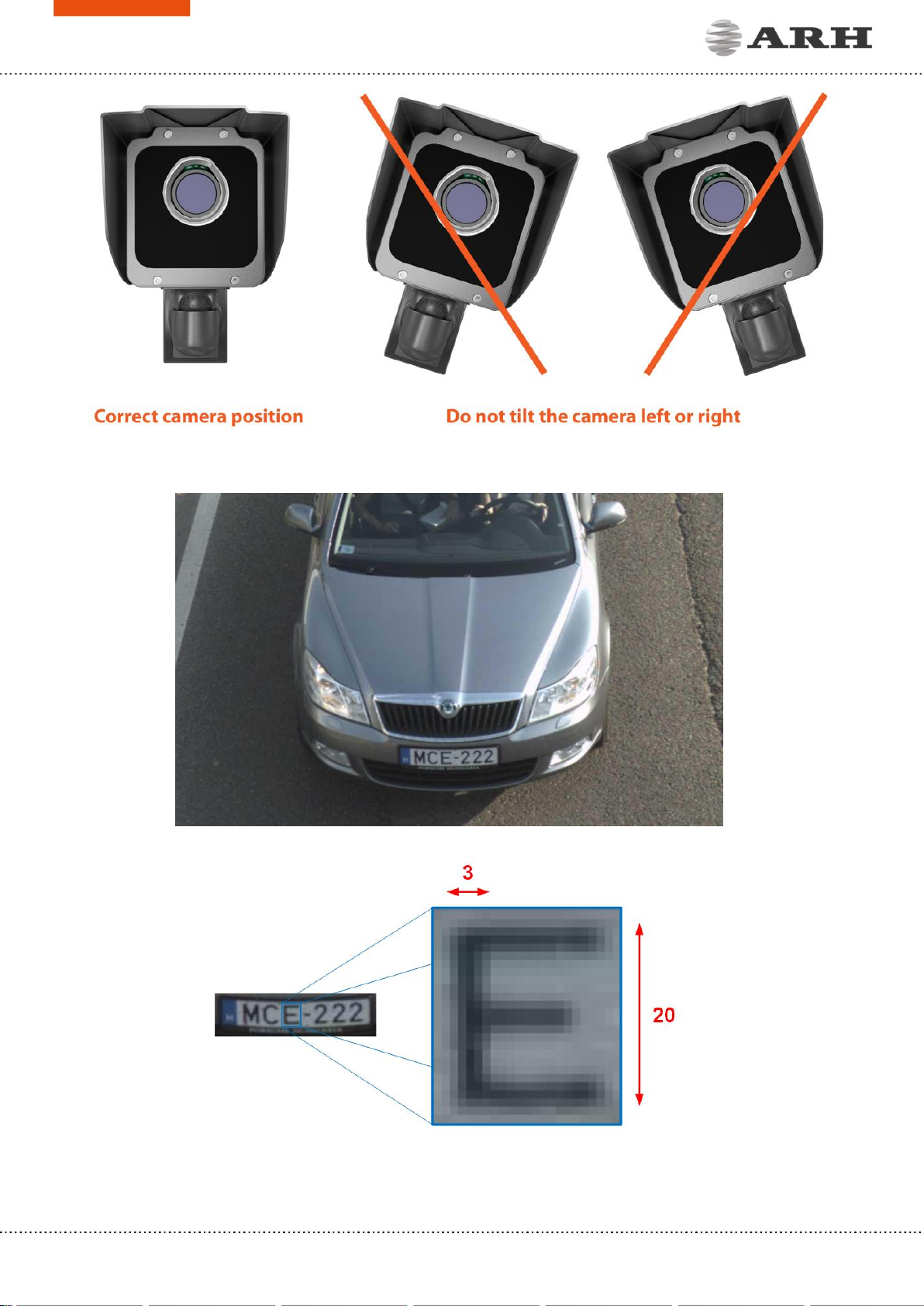
you want to achieve over 95% recognition rate with short recognition times, you have to calculate
the position of the camera accurately. The best position is if the camera is installed on gentry
above the traffic lane (see below).
If there is no possibility to install a gentry above the concerned road section the installation of
the camera can be done near the road. In this case the angle between the camera axis and the
direction of the vehicle movement should be minimal and the camera should be installed 1 –
1,5 meters above the headlights of the vehicles.
The distance between the camera and plate is also important. If the camera is too far from the
plate, the characters may not be large enough for recognizing them. In this case, zoom-in until
you reach the proper size. If the distance is too short it may happen that a part of the plate is
over the camera’s field of view (when the vehicle is near to the side of the lane or the plate is
not at the middle of the vehicle).
From the point of ANPR/LPR the most important is the size of the characters on the image. For
English characters it is recommended to have at least 16 pixel average character height, for
Arabic or other special characters it is recommended to have 20 pixel height (due to they are
more calligraphic than the English characters). The too large characters are also not suitable for
ANPR, therefore try to avoid settings where the character size is greater than 50 pixels in height.
A line width of a character on the image should be at least 2 pixels.

Page 10/14
SmartCAM Install Guide
A properly set camera should provide a similar image:
A proper sample image
Proper character sizes (in pixels) on the sample image

Page 11/14
SmartCAM Install Guide
MAINTENANCE / STORAGE
The cameras are designed for 24/7/365 work for every weather condition and they do not need
special maintenance. Please keep the front of the camera clean. During the cleaning process,
avoid scratching the front cover.
Do not use the camera without its sun-shield in hot environment, because it was specially
designed to provide proper air-cooling.
The cameras should be stored in low humidity environment in temperature range of -35 °C to
+ 50 °C. Always use the sealing caps on the connectors to keep the camera unit waterproof. If
you miss to use it, the warranty will be void.
The maintenance of the devices is recommended on a quarterly basis. In case of extreme weather
conditions more often.
During the maintenance make sure that:
the camera operates properly,
it is facing to the previously set direction,
the fastening does not slack,
the front of the camera and the camera itself is clean (no spider webs or any other
contaminants inhibit the visibility),
there are no strange circumstances (vapor, damage).
The device is equipped with an 850nm InfraRed illumination unit. The human eye will
not or slightly see this light coming from the LED’s. Do not look into the illumination
unit directly from close range or for more than 100 seconds. If you do not take these
safety precautions, you risk damaging your eyes.

Page 12/14
SmartCAM Install Guide
PC RECOVERY MODE
The PC of the camera has a Recovery Mode primarily designed to maintain the communication
with the camera when it is unreachable for various reasons e.g. due to misconfiguration or the
IP address of the device is lost.
ENTERING RECOVERY MODE
Starting of the Recovery mode can be implemented in the
following way:
By magnetization:
1. Power off the camera.
2. Touch a magnet (not included) to the bottom of the PC at
the back of the camera and hold it in position. See figure
on the right.
3. Power on the camera and wait 5 seconds.
4. Remove the magnet.
5. Reach the camera via its default (192.168.1.4) IP address.
After this process, the following window will appear on your browser:
After clicking the [Restore Factory State] button on the bottom left side of the window, the PC
will return with the factory settings in a few seconds.

Page 13/14
SmartCAM Install Guide
APPENDIX
ADDING ALTERNATE IP ADDRESS
WINDOWS VISTA/WINDOWS 7
1. Click Start and select Control Panel.
Select either the Small icons or Large icons
option from the View by drop-down menu
which is found on the upper right hand side
of the window.
2. Open Network and Sharing Center.
3. Click Change adapter settings (Win7/8) on
the left side of Network and Sharing Center.
4. Right click on the network connection you
want to add an IP address (to the one the
camera has been connected to) and select
Properties.
5. Look for Internet Protocol Version 4
(TCP/IP v4) and press the Properties button.
6. Select Obtain an IP address automatically and click on the Alternate Configuration tab.
7. Select User configured and enter an IP address (e.g.: 192.168.1.54). The Subnet mask
should be 255.255.255.0 as shown on
Figure 1.
8. Click OK in the opened windows to close them.
LINUX
1. Open a terminal.
2. Enter the ifconfig command to see the reserved Ethernets (e.g. eth0).
3. Enter the following command: ifconfig ethY192.168.1.25
where Yis a free eth (e.g. eth1) and 192.168.1.25 is a sample IP address.
Figure 1.

Page 14/14
SmartCAM Install Guide
CONTACT INFORMATION
HEADQUARTERS:
ARH Inc.
Alkotás utca 41
HU-1123 Budapest
Hungary
Phone: +36 1 201 9650
Fax: +36 1 201 9651
Web: www.arh.hu
ARH AMERICA:
ARA Corp.
28059 US Highway 19 North Suite
203
Clearwater, FL 33761
Phone: (727) 724-4219
Fax: (727) 724-4290
Web: www.adaptiverecognition.com
SERVICE ADDRESS:
ARH Inc.
Ipari Park HRSZ 1113/1
HU-2074 Perbál
Hungary
Phone: +36 1 2019650
ARH Technical Support System (ATSS) is designed to provide you the fastest and most proficient
assistance, so you can quickly get back to business.
Information regarding hardware, software, manuals and FAQ are easily accessible for customers
who previously registered to enter the dedicated ATSS site. Besides offering assistance, the site
is also designed to provide maximum protection while managing your business information and
technical solutions utilized.
NEW USER
If this is your first online support request, please create an account by clicking on this link.
RETURNING USER
All registered ATSS customers receive a personal access link via e-mail. If you previously received
a confirmation message from ATSS, it contains the embedded link that allows you to securely
enter the support site.
Table of contents
Other ARH Digital Camera manuals