Imaging Source DMK 33UX183 Product manual

DMK 33UX183
Technical Reference Manual

DMK 33UX183 Technical ReferenceManual 2
Table of Contents
1. Quick Facts 4
2. Dimensional Diagrams 6
2.1 DMK 33UX183 C-Mount with Tripod Adapter ............................................................. 6
2.2 DMK 33UX183 C-Mount without Tripod Adapter ....................................................... 7
2.3 DMK 33UX183 CS-Mount with Tripod Adapter ........................................................... 8
2.4 DMK 33UX183 CS-Mount without Tripod Adapter ..................................................... 9
3. I/O Connector 10
3.1 12-pin I/O Connector ................................................................................................... 10
TRIGGER_IN ........................................................................................................... 113.1.1 STROBE_OUT ......................................................................................................... 113.1.2
4. Spectral Characteristics 12
4.1 Spectral Sensitivity - IMX183CLK-J ............................................................................. 12
5. Camera Controls 13
5.1 Sensor Readout Control .............................................................................................. 13
Pixel Format ........................................................................................................... 135.1.1 8-Bit Monochrome ................................................................................................................................. 135.1.1.1
12-Bit Packed Monochrome ................................................................................................................ 145.1.1.2
16-Bit Monochrome .............................................................................................................................. 145.1.1.3
Resolution .............................................................................................................. 145.1.2 Readout Modes ...................................................................................................... 155.1.3 Frame Rate ............................................................................................................. 165.1.4 Partial Scan Offset ................................................................................................. 175.1.5 Image Flipping ....................................................................................................... 185.1.6
5.2 Image Sensor Control .................................................................................................. 18
Exposure Time ....................................................................................................... 185.2.1 Gain ........................................................................................................................ 195.2.2 Black Level ............................................................................................................. 195.2.3
5.3 Automatic Exposure and Gain Control ...................................................................... 20
Auto Exposure ........................................................................................................ 205.3.1 Auto Gain ............................................................................................................... 205.3.2 Auto Reference Value ............................................................................................ 215.3.3 Highlight Reduction ............................................................................................... 215.3.4 Auto Exposure Limits ............................................................................................. 215.3.5 Auto Gain Limits .................................................................................................... 225.3.6
5.4 Trigger ........................................................................................................................... 23
Trigger Mode ......................................................................................................... 235.4.1 Trigger Polarity ...................................................................................................... 235.4.2 Trigger Operation .................................................................................................. 245.4.3 Software Trigger .................................................................................................... 245.4.4

DMK 33UX183 Technical ReferenceManual 3
Table of Contents
Trigger Burst Count ................................................................................................ 245.4.5 Trigger Source ........................................................................................................ 255.4.6 Trigger Overlap ...................................................................................................... 255.4.7
5.5 Trigger Timing Parameters .......................................................................................... 25
Trigger Delay ......................................................................................................... 265.5.1 Trigger Debounce Time ......................................................................................... 265.5.2 Trigger Mask Time ................................................................................................. 265.5.3 Trigger Noise Suppression Time ............................................................................ 275.5.4
5.6 Digital I/O ..................................................................................................................... 27
General Purpose Input ........................................................................................... 275.6.1 General Purpose Output ........................................................................................ 285.6.2
5.7 Strobe ........................................................................................................................... 28
Strobe Enable ......................................................................................................... 285.7.1 Strobe Polarity ........................................................................................................ 295.7.2 Strobe Operation .................................................................................................... 295.7.3 Strobe Duration ...................................................................................................... 305.7.4 Strobe Delay ........................................................................................................... 305.7.5
5.8 Image Processing ......................................................................................................... 30
Gamma ................................................................................................................... 305.8.1 Lookup Table .......................................................................................................... 315.8.2
5.9 Region of Interest for Auto Functions ....................................................................... 32
Auto Functions ROI Enable .................................................................................... 325.9.1 Auto Functions ROI Preset ..................................................................................... 325.9.2 Auto Functions ROI Custom Rectangle .................................................................. 335.9.3
5.10 User Sets ....................................................................................................................... 34
User Set Selector .................................................................................................... 345.10.1 Load User Set ......................................................................................................... 345.10.2 Save User Set ......................................................................................................... 355.10.3 Default User Set ..................................................................................................... 355.10.4
6. Revision History 36
DMK 33UX183 Technical ReferenceManual 4
Quick Facts
1 Quick Facts
General
Vision Standard
USB3 Vision
Dynamic Range
12
Resolution
5472x3648
Frame Rate at Full Resolution
18
Pixel Formats
8-Bit Monochrome
12-Bit Packed Monochrome
16-Bit Monochrome
Optical Interface
IR-Cut filter
No
Sensor Type
Sony IMX183CLK-J
Shutter Type
Rolling
Sensor Format
1 inch
Pixel Size
2.4 µm
Lens Mount
C/CS
Electrical Interface
Interface
USB 3.0
Supply voltage
4.75 VDC to 5.25 VDC
Current consumption
approx 660 mA @ 5 VDC
I/O Connector
12-pin connector for trigger and strobe or
general purpose input/output
Mechanical Data
Dimensions
H: 29 mm, W: 29 mm, L: 43 mm
Mass
65 g
Adjustments
Shutter
50 µs to 30 s
Gain
0 dB to 2704 dB

DMK 33UX183 Technical ReferenceManual 5
Quick Facts
Environmental
Temperature (operating)
-5 °C to 45 °C
Temperature (storage)
-20 °C to 60 °C
Humidity (operating)
20 % to 80 % (non-condensing)
Humidity (storage)
20 % to 95 % (non-condensing)
DMK 33UX183 Technical ReferenceManual 6
Dimensional Diagrams
2 Dimensional Diagrams
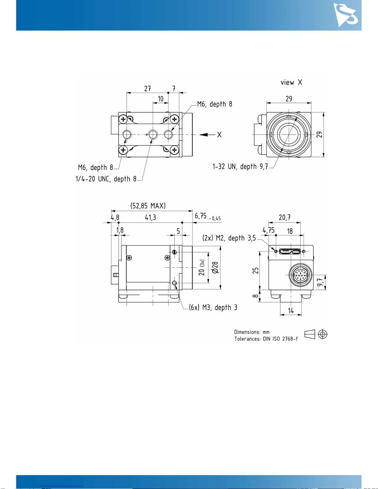
2.1 DMK 33UX183 C-Mount with Tripod Adapter
DMK 33UX183 Technical ReferenceManual 7
Dimensional Diagrams
2.2 DMK 33UX183 C-Mount without Tripod Adapter
DMK 33UX183 Technical ReferenceManual 8
Dimensional Diagrams
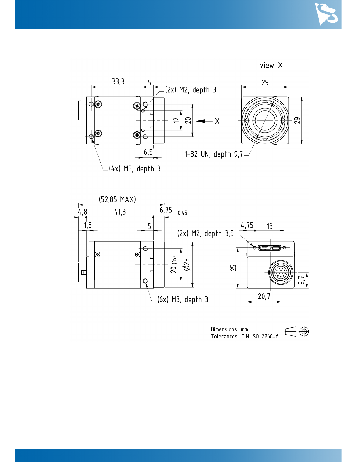
2.3 DMK 33UX183 CS-Mount with Tripod Adapter

DMK 33UX183 Technical ReferenceManual 9
Dimensional Diagrams
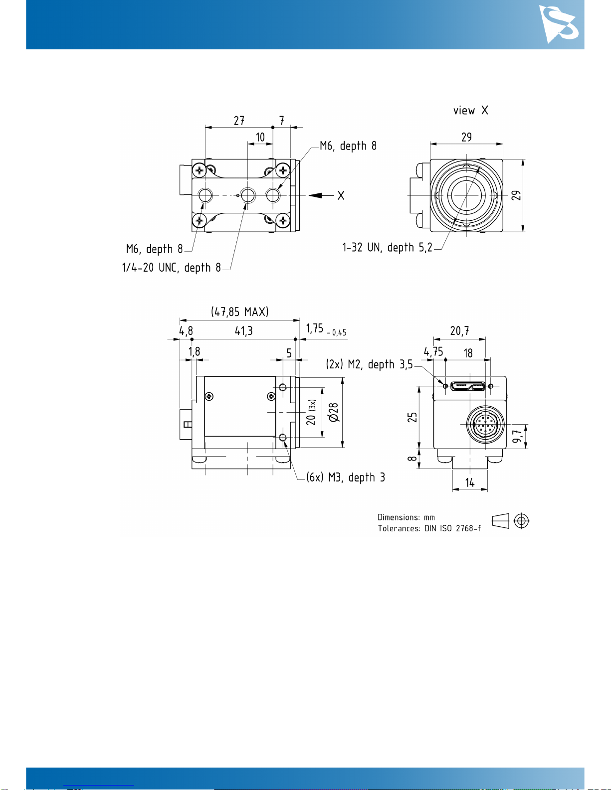
2.4 DMK 33UX183 CS-Mount without Tripod Adapter
DMK 33UX183 Technical ReferenceManual 10
I/O Connector
3 I/O Connector
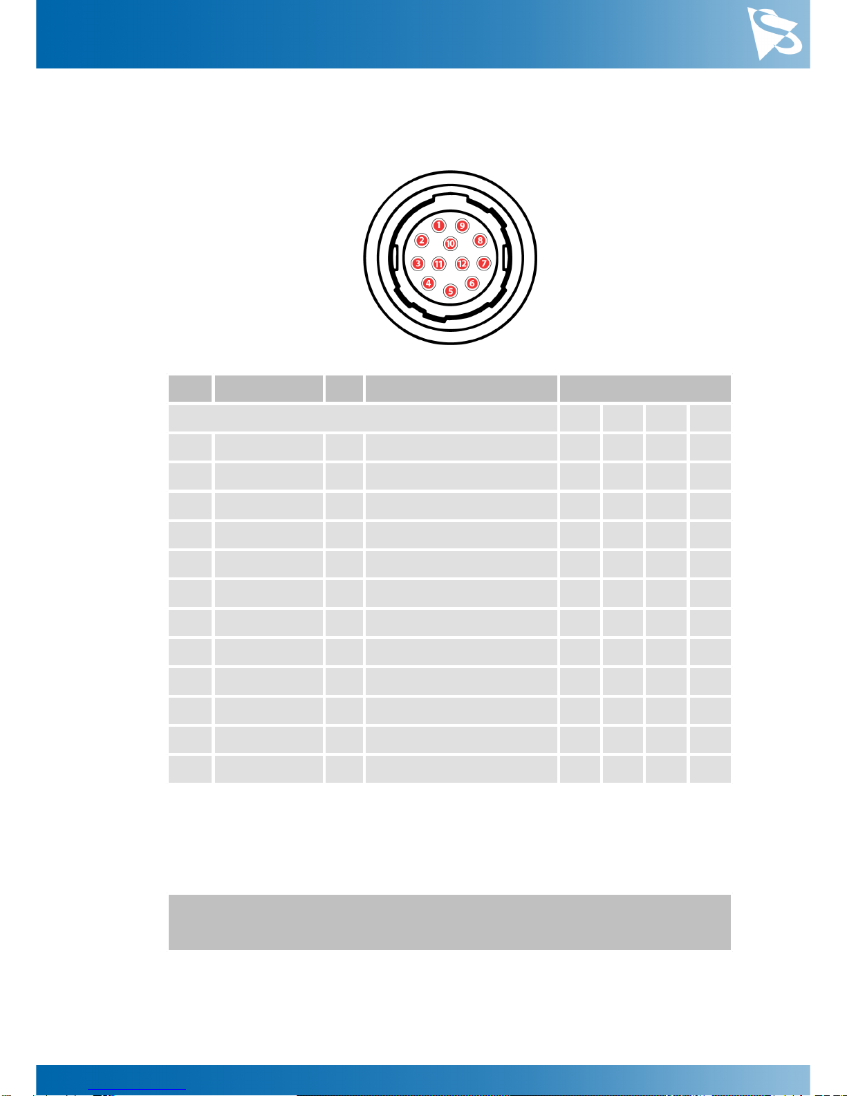
3.1 12-pin I/O Connector
Rear view of camera
Pin
Signal
I/O
Remarks
Characteristics
Min
Typ
Max
Unit
1
do not use
-
-
-
-
-
2
do not use
-
-
-
-
-
3
n.c.
-
-
-
-
-
4
n.c.
-
-
-
-
-
5
n.c.
-
-
-
-
-
6
n.c.
-
-
-
-
-
7
GND_I/O
G3
External Ground
-
-
-
-
8
n.c.
-
-
-
-
-
9
n.c.
-
-
-
-
-
10
STROBE_OUT
O3
Open drain
-
-
24.01
V
11
TRIGGER_IN (+)
I3
Optocoupler signal
3.32
-
24.02
V
12
TRIGGER_IN (-)
I3
Optocoupler ground
-
-
-
-
1max. 0.2A (ID) for open drain MOSFET!
2min. 3.5 mA driver strength required!
3G: Ground O: Output I: Input
The part number of this Hirose connector is HR10A10R-12P(73). To create an I/O
cable you need a Hirose connector HR10A-10P-12S(73).

DMK 33UX183 Technical ReferenceManual 11
I/O Connector
3.1.1 TRIGGER_IN
The TRIGGER_IN line can be used to synchronize the start of the exposure time with
external events. The Trigger section describes in detail how the image sensor's behavior
can be controlled.
The current input signal can also be read directly through the General Purpose Input
feature.
3.1.2 STROBE_OUT
The STROBE_OUT line's main usage is to indicate the integration time of the image
sensor which allows flashes, strobes or other light sources to be synchronized with
camera operation. The line's behavior can be controlled through the Strobe controls.
The output signal can also be directly controlled through the General Purpose Output
feature.
DMK 33UX183 Technical ReferenceManual 12
Spectral Characteristics
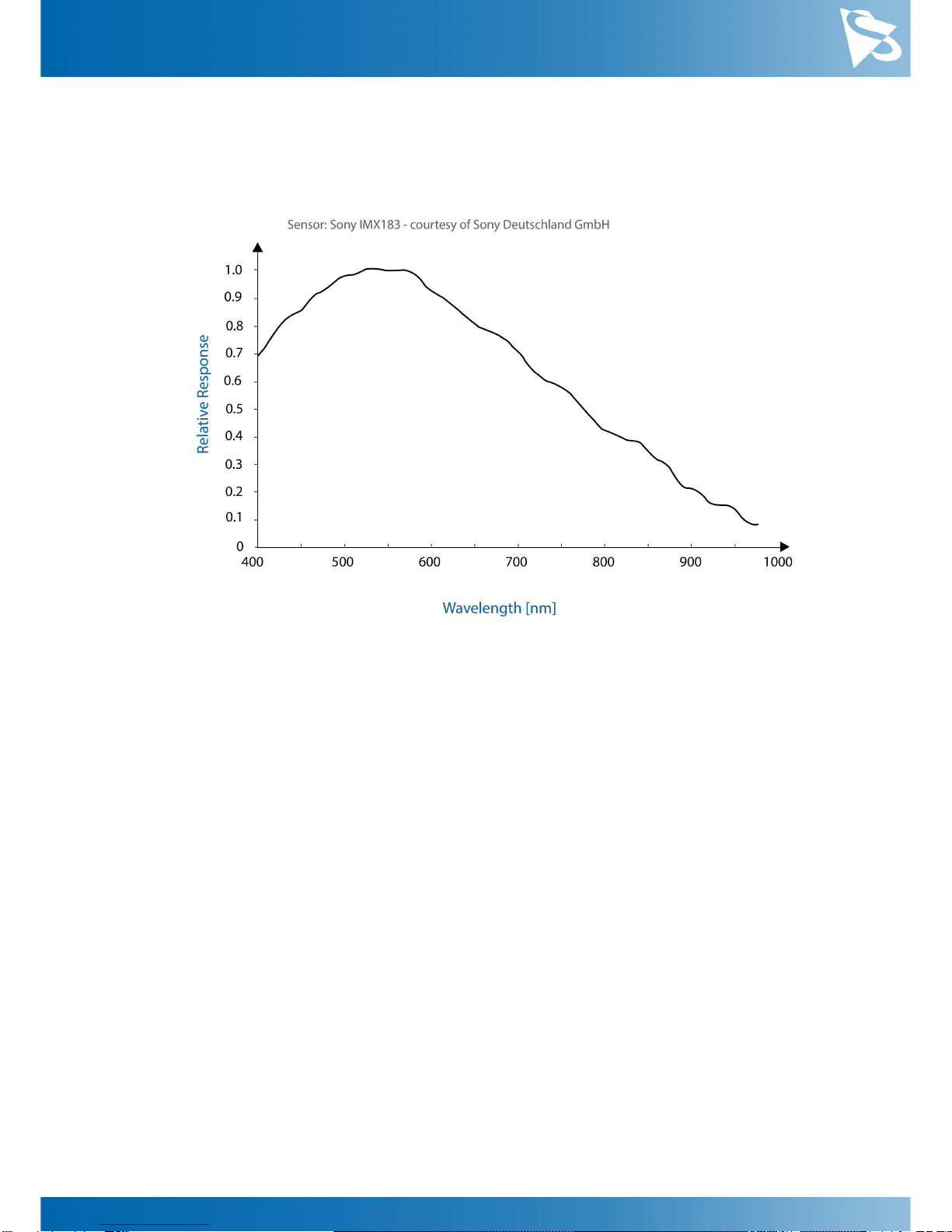
4 Spectral Characteristics
4.1 Spectral Sensitivity - IMX183CLK-J
DMK 33UX183 Technical ReferenceManual 13
Camera Controls
5 Camera Controls
This section describes the parameters available for the DMK 33UX183 camera.
The actual name of the parameter depends on the driver technology used to access the
camera. Parameter names are listed for the most common ways to access the cameras:
·
USB3 Vision (cross platform, via 3rd party driver)
·
UVC/V4L2 (on Linux, via uvcvideo)
·
IC Imaging Control (on Windows, via Device Driver for The Imaging Source USB 33U,
37U and 38U Cameras)
5.1 Sensor Readout Control
5.1.1 Pixel Format
The pixel format defines the data type of the pixels transmitted to the computer. The
bits per pixel needed for a particular pixel format influence the required bandwith.
The way the pixel format is controlled varies significantly among the driver technology
used to access the camera:
·
When using USB3 Vision, the pixel format is controlled through the PixelFormat
GenICam feature.
·
When using the uvcvideo driver on Linux, the pixel format is defied by video4linux2.
·
When using IC Imaging Control, the pixel format is part of the video format - a
parameter which combines pixel format, resolution and readout mode. For more
information, refer to the IC Imaging Control documentation sections on
VideoFormat and VideoFormatDesc.
The DMK 33UX183 monochrome camera supports multiple pixel formats with variable
bits-per-pixel settings. The names of the pixel formats and the way to select them
depends on the driver used to control the camera. The following table contains a short
overview of all possible formats followed by a more detailed description.
Pixel Format
Bits Per Pixel
USB3 Vision
UVC
TIS UVC Driver
8-Bit
Monochrome
8
Mono8
Y800
Y800
12-Bit Packed
Monochrome
12
Mono12p
Y12p
Y16
16-Bit Packed
Monochrome
16
Mono16
Y16
Y16
5.1.1.1 8-Bit Monochrome
This format transmits data using one byte for each pixel.
USB3 Vision drivers see this pixel format as Mono8.

DMK 33UX183 Technical ReferenceManual 14
Camera Controls
UVC drivers see it with the FourCC Y800.
The Device Driver for The Imaging Source USB 33U, 37U and 38U Cameras offers this
pixel format as the Y800 video format.
5.1.1.2 12-Bit Packed Monochrome
This format transmits data using 3 bytes for each pair of 2 consecutive pixels.
USB3 Vision drivers see this pixel format as Mono12p.
UVC drivers see it with the FourCC Y12p.
The Device Driver for The Imaging Source USB 33U, 37U and 38U Cameras offers this
pixel format as the Y16 video format. Since the DMK 33UX183 camera offers both 12-
bit packed and 16-bit monochrome pixel formats, the driver will use the 12-bit packed
format when the Y16 video format is selected.
5.1.1.3 16-Bit Monochrome
The sensor of the DMK 33UX183 camera is not capable of providing 16-bit data output.
Instead, the pixel data is transmitted in the most significant bits which allows
application programs to ignore the sensor-specific data type, and treat the data as if
the sensor outputs 16 bits.
USB3 Vision drivers see this pixel format as Mono16.
UVC drivers see it with the FourCC Y16.
The Device Driver for The Imaging Source USB 33U, 37U and 38U Cameras offers this
pixel format as the Y16 video format.
5.1.2 Resolution
The DMK 33UX183 allows the user to specify which rectangular region of the image
sensor to read out during camera operation. The size of this rectangle determines the
number of pixels that have to be transferred for each frame and has a significant
influence on the required USB bandwidth.
Lowering the resolution also often allows the image sensor to operate at a higher frame
rate. Changes in the vertical resolution have more effect on the maximum frame rate
than changes in the horizontal direction.
The way the resolution is controlled varies greatly between the driver technology used
to access the camera:
·
When using USB3 Vision, the resolution is controlled through the GenICam features
Width and Height.
·
When using the uvcvideo on Linux, the resolution is selected from a list of fixed
formats. Dynamic frame sizes are not available.
·
When using IC Imaging Control, the resolution is part of the video format, a parameter
that combines pixel format, resolution and readout mode. For more information, refer
DMK 33UX183 Technical ReferenceManual 15
Camera Controls
to the IC Imaging Control documentation sections on VideoFormat and
VideoFormatDesc.
Parameter
Horizontal Resolution
Minimum
256
Maximum
5472
USB3 Vision: GenICam
Width
Parameter
Vertical Resolution
Minimum
4
Maximum
3648
USB3 Vision: GenICam
Height
5.1.3 Readout Modes
The DMK 33UX183 camera offers different sensor readout modes.
By default, the camera outputs all pixels of the image sensor.
In skipping modes, the image sensor regularly skips a number of rows and/or columns
during readout. The resulting output image is smaller but contains the same field of
view than the image produced by default readout mode.
In binning modes, a number of neighboring pixels is merged into one output pixel
during readout. The nature of this merge operation is sensor-specific, most sensors
either add the pixel values or average them.
Generally, binning modes provide better image quality than skipping modes. However,
skipping modes usually provide a higher maximum frame rate.
The way the readout modes are controlled depends greatly upon which driver
technology is used to access the camera:
·
When using USB3 Vision, the readout mode is controlled through the GenICam
features DecimationHorizontal, DecimationVertical, BinningHorizontal
and BinningVertical.
·
Selecting readout modes is currently not supported through UVC in Linux.
·
When using IC Imaging Control, the readout mode is part of the video format - a
parameter that which combines pixel format, resolution and readout mode. For more
information, refer to the IC Imaging Control documentation sections on
VideoFormat and VideoFormatDesc.
The following readout modes are supported:
·
Default
·
Binning 2X
DMK 33UX183 Technical ReferenceManual 16
Camera Controls
5.1.4 Frame Rate
The frame rate is specified in frames per second and determines the camera's operating
speed.
The way the frame rate is controlled depends greatly upon which driver technology is
used to access the camera:
·
When using USB3 Vision, the frame rate is controlled through the GenICam feature
AcquisitionFrameRate.
·
When using uvcvideo on Linux, the frame rate is selected from a list of available
frame rates.
·
When using IC Imaging Control, the frame rate is selected from a list of available
frame rates through APIs such as Grabber::setFPS or
ICImagingControl.DeviceFrameRate.
The range of available frame rates depends upon other camera settings such as well,
pixel format, resolution and readout modes.
Parameter
Frame Rate
Minimum
Depending on Pixel Format, Resolution, and Readout
Mode
Maximum
Depending on Pixel Format, Resolution, and Readout
Mode
USB3 Vision: GenICam
AcquisitionFrameRate
The following tables show the maximum frame rate for some combinations of pixel
format and resolution.
8-Bit Monochrome
Width
Height
Maximum Frame Rate
5472
3648
18
3840
2160
31
1920
1080
60
640
480
125
12-Bit Packed Monochrome
DMK 33UX183 Technical ReferenceManual 17
Camera Controls
Width
Height
Maximum Frame Rate
5472
3648
12
3840
2160
20
1920
1080
40
640
480
83
16-Bit Monochrome
Width
Height
Maximum Frame Rate
5472
3648
9
3840
2160
15
1920
1080
30
640
480
62
5.1.5 Partial Scan Offset
If the selected resolution is smaller than the sensor size, the part of the sensor that is
actually read out can be specified by the Partial Scan Offset X and Partial Scan Offset Y
parameters. By default, the camera automatically positions the offsets so that the center
of the sensor is used.
Parameter
Partial Scan Offset X
Minimum
0
Maximum
5216
USB3 Vision: GenICam
OffsetX
Video4Linux2
ROI Offset X
VCD Property
VCDID_PartialScanOffset
\VCDElement_PartialScanOffsetX
Parameter
Partial Scan Offset Y
Minimum
0
Maximum
3644
USB3 Vision: GenICam
OffsetY
Video4Linux2
ROI Offset Y
VCD Property
VCDID_PartialScanOffset
\VCDElement_PartialScanOffsetY

DMK 33UX183 Technical ReferenceManual 18
Camera Controls
If Partial Scan Offset X or Partial Scan Offset Y is configured to a value that would be
invalid with the current setting of Resolution setting, the camera uses the maximum
possible value.
Parameter
Partial Scan Auto Center
On
Automatically configure Partial Scan Offset X/Y so that
the center area of the sensor is read out
True
Off
Control Partial Scan Offset X/Y manually
False
USB3 Vision: GenICam
OffsetAutoCenter
Video4Linux2
ROI Auto Center
VCD Property
VCDID_PartialScanOffset
\VCDElement_PartialScanAutoCenter
5.1.6 Image Flipping
The DMK 33UX183 camera allows for vertical flipping of the image data. The Flip
Vertical parameter can be used to control this sensor feature.
Parameter
Flip Vertical
True
Image data is flipped vertically
False
Image data is not flipped vertically
USB3 Vision: GenICam
ReverseY
Video4Linux2
Flip Vertical
VCD Property
VCDID_FlipVertical\VCDElement_Value
5.2 Image Sensor Control
5.2.1 Exposure Time
The Exposure Time parameter defines the time the camera opens its (electronic) shutter
when it is taking an image.

DMK 33UX183 Technical ReferenceManual 19
Camera Controls
Parameter
Exposure Time
Minimum
50 µs
Maximum
30 s
Default
auto
USB3 Vision: GenICam
ExposureTime
Video4Linux2
Exposure Time (us)
VCD Property
VCDID_Exposure\VCDElement_Value
5.2.2 Gain
The Gain parameter defines the amplification that is applied to the image at sensor
level.
Parameter
Gain
Minimum
0 dB
Maximum
2704 dB
Default
auto
USB3 Vision: GenICam
Gain
Video4Linux2
Gain (db/100)
VCD Property
VCDID_Gain\VCDElement_Value
5.2.3 Black Level
The Black Level parameter defines the lowest possibly intensity value of the image
sensor.
Parameter
Black Level
Minimum
0
Maximum
1023
Default
50
USB3 Vision: GenICam
BlackLevel
Video4Linux2
Brightness
VCD Property
VCDID_Brightness\VCDElement_Value
DMK 33UX183 Technical ReferenceManual 20
Camera Controls
5.3 Automatic Exposure and Gain Control
The DMK 33UX183 camera can automatically control gain and exposure time. These
automatic functions are enabled by default.
In order to optimize image parameters, a region of interest can be specified for
automatic functions. Specifying a region of interest enables fine-grained control over
the image area for which the image parameters are optimized. A selection of pre-
defined area presets is available, but the user can also specify the coordinates of a
custom rectangle.
In certain situations, it is desirable to limit the range of the auto-controlled parameters.
For example, one might want to avoid high gain settings in order to keep noise levels
low. Other applications require limiting the maximum exposure time so that
movements do not get blurred. Therefore, the ranges of the gain and exposure
parameter can be limited.
If both auto exposure and auto gain are active, the camera tries to lower the gain value
in order to reduce noise and improve the image quality.
5.3.1 Auto Exposure
Parameter
Auto Exposure
Continuous
Enable Auto Exposure
True
Off
Disable Auto Exposure
False
USB3 Vision: GenICam
ExposureAuto
Video4Linux2
Auto Shutter
VCD Property
VCDID_Exposure\VCDElement_Auto
5.3.2 Auto Gain
Parameter
Auto Gain
Continuous
Enable Auto Gain
True
Off
Disable Auto Gain
False
USB3 Vision: GenICam
GainAuto
Video4Linux2
Auto Gain
VCD Property
VCDID_Gain\VCDElement_Auto
Table of contents
Other Imaging Source Digital Camera manuals


