IMAGO VisionBox DAYTONA User manual
Hardware Manual
VisionBox DAYTONA
Version 1.0 –May 2019

Handling and Safety Instructions Page 2 / 22
IMAGO Technologies GmbH
Strassheimer Str. 45; 61169 Friedberg - Germany; Tel. +49 6031-6842611
info@imago-technologies.com; www.imago-technologies.com
Contents
1Handling and Safety Instructions ________________________________3
2Introduction ____________________________________________________4
2.1 Concept.................................................................................................................... 5
2.2 Configurations ........................................................................................................ 6
2.3 Block Diagram......................................................................................................... 7
3Technical Data _________________________________________________8
3.1 Operating Conditions............................................................................................. 8
3.2 Dimensions............................................................................................................ 10
4Power Connector and LEDs ____________________________________11
4.1 Power Connector.................................................................................................. 11
4.2 System LEDs......................................................................................................... 11
5Interfaces _____________________________________________________12
5.1 Ethernet.................................................................................................................. 12
5.1.1 Power-over-Ethernet _______________________________________________ 12
5.1.2 Trigger-over-Ethernet_______________________________________________ 12
5.2 USB 3.0................................................................................................................... 13
5.3 Micro USB Service Port ....................................................................................... 13
5.4 DisplayPort............................................................................................................ 14
5.5 SD Card.................................................................................................................. 14
5.6 Wi-Fi and Bluetooth.............................................................................................. 14
5.7 4G / LTE Modem.................................................................................................... 14
5.8 Digital I/O ............................................................................................................... 15
5.9 RS-422.................................................................................................................... 17
6Internal Connectors____________________________________________18
6.1 M.2 SSD.................................................................................................................. 19
6.2 M.2 LTE Modem .................................................................................................... 20
6.3 Nano SIM................................................................................................................ 20
7Support _______________________________________________________21
8History________________________________________________________22
Handling and Safety Instructions Page 3 / 22
IMAGO Technologies GmbH
Strassheimer Str. 45; 61169 Friedberg - Germany; Tel. +49 6031-6842611
info@imago-technologies.com; www.imago-technologies.com
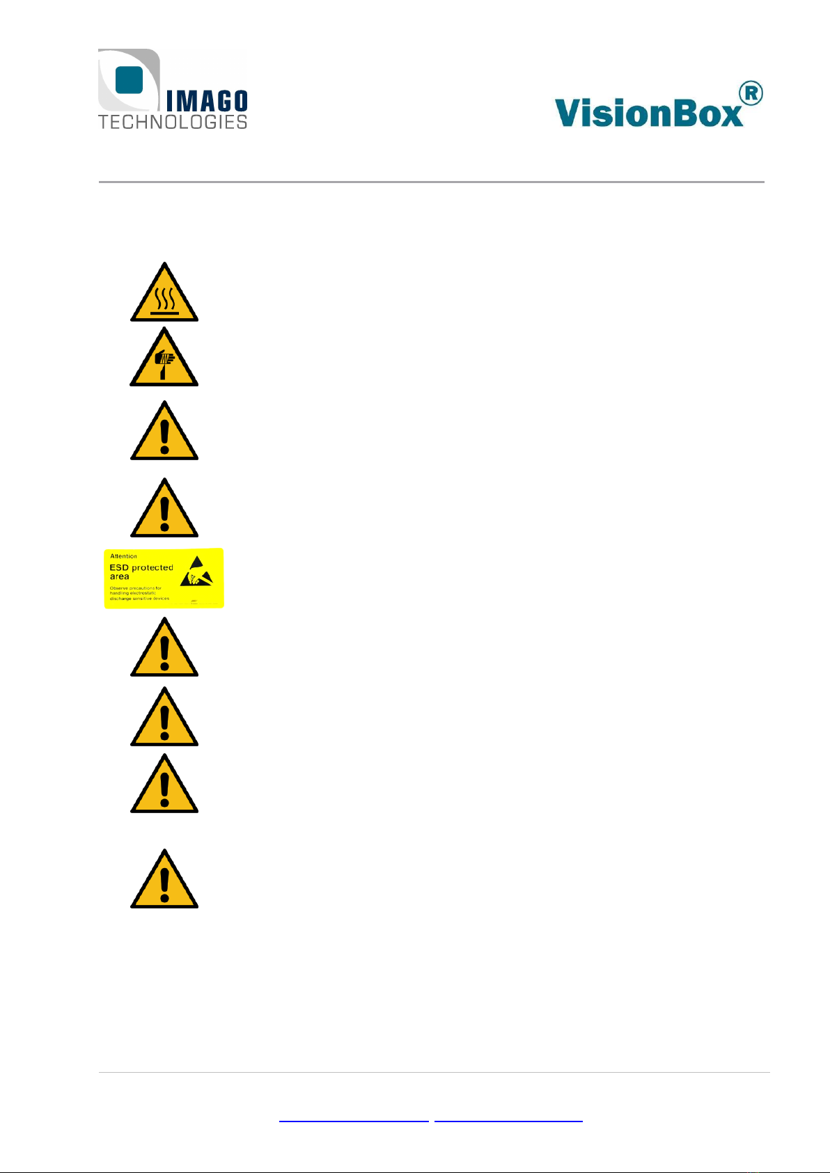
1Handling and Safety Instructions
Depending on the operating conditions, the housing temperature can exceed
60 °C. There is a risk of injury!
Handle with care! The housing, especially heat sinks, can have sharp edges. There
is a risk of injury!
EMC conformity according to EN/IEC 61000-6-2:2005 is qualified for cable lengths
≤ 30 m.
Electrostatic discharge at unshielded I/O connectors can lead to unexpected
events or data errors for the corresponding interface.
Electrical installation should be executed without power applied to the device
and connected devices.
Before opening the housing, make sure that the VisionBox is disconnected from
power.
Use appropriate ESD protection when changing components.
Please take special note of the voltage range which may be applied to the device.
Otherwise, permanent damage to the device may result!
Air Circulation
When mounting the device within an enclosure, adequate space for air circula-
tion is required. The space above, below and at both sides should be at least 5
cm.
Avoid extreme environmental conditions and protect the VisionBox from dust,
humidity and heat.
Due to the characteristics and physical principles inside flash memory, SSDs have
a finite lifetime dictated by the number of write operations.
Therefore, take care of the regular write operations to prevent an early SSD
damage. Ask for the technical data of the used SSD and, if necessary, for support
to calculate the lifetime.
Inform the user of the system that SSDs are wear parts which must be renewed
regularly.

2 Introduction Page 4 / 22
IMAGO Technologies GmbH
Strassheimer Str. 45; 61169 Friedberg - Germany; Tel. +49 6031-6842611
info@imago-technologies.com; www.imago-technologies.com
2Introduction
Thank you very much for your interest in our VisionBox DAYTONA. To get the most out of your
purchase, please take some time to read all the information given here thoroughly.
The VisionBox provides three Gigabit Ethernet ports and two USB 3.0 ports. To avoid complex
cabling, two Ethernet ports have support for PoE and the GigE Action Command. This allows
transferring data, power and trigger signal using a single Ethernet cable.
The integrated Real-Time Communication Controller (RTCC) ensures proper timing for trigger sig-
nals, even without any real-time operating system. The IMAGO SDK provides a consistent C++
programming interface for controlling the RTCC.
Due to its small size, powered by 24VDC and without fan, the VisionBox can be mounted into near-
ly every machine. All components are available for several years, for continuous delivery without
changes. For series production, IMAGO delivers the VisionBox ready-to-run, including a customer-
specific root filesystem, qualified 3rd-party components and acceptance test.

2 Introduction Page 5 / 22
IMAGO Technologies GmbH
Strassheimer Str. 45; 61169 Friedberg - Germany; Tel. +49 6031-6842611
info@imago-technologies.com; www.imago-technologies.com
2.1 Concept
A Real-Time Communication Controller with vision- & automation-specific interfaces combined
with an embedded ARM processor and integrated GPU, this is the philosophy of the VisionBox
DAYTONA:
NVIDIA Tegra TX2 SoC
oQuad-core ARM Cortex-A57 @ 2 GHz
oDual-core Denver 2 @ 2 GHz
oGPU: NVIDIA Pascal™ architecture with 256 CUDA cores
o8 GB DDR4 RAM
o32 GB eMMC
Real-Time Communication Controller –RTCC
oControls vision- & automation-specific interfaces:
▪Digital I/Os
▪Encoder
▪Camera Trigger
oContains functional units for controlling I/Os in real time:
▪Trigger unit: creation of trigger signals, derived from other inputs (e.g. en-
coder)
▪I/O Scheduler: applies values stored in a FIFO to outputs in real time (based
on trigger event, encoder position or timer value)
▪Multiplexer: Flexible connection of functional units
oOperates independently from the OS & the processor
oEasy-to-use high-level API for C++
Camera Interfacing:
oPower-over-Ethernet: two independent Ethernet ports with PoE support
oTrigger-over-Ethernet: Real-time trigger from RTCC with a µs-jitter
Digital I/Os:
oOpto-isolated
oStatus LEDs
oInputs up to 5 MHz with debouncing in RTCC. Communicated to CPU via interrupt
or polling
oOutputs up to 50 kHz
Housing
oPassive cooling
o24 VDC power input
oNo moving parts
Wireless communication
oWIFI and Bluetooth integrated
oLTE / 4G modem option

2 Introduction Page 6 / 22
IMAGO Technologies GmbH
Strassheimer Str. 45; 61169 Friedberg - Germany; Tel. +49 6031-6842611
info@imago-technologies.com; www.imago-technologies.com
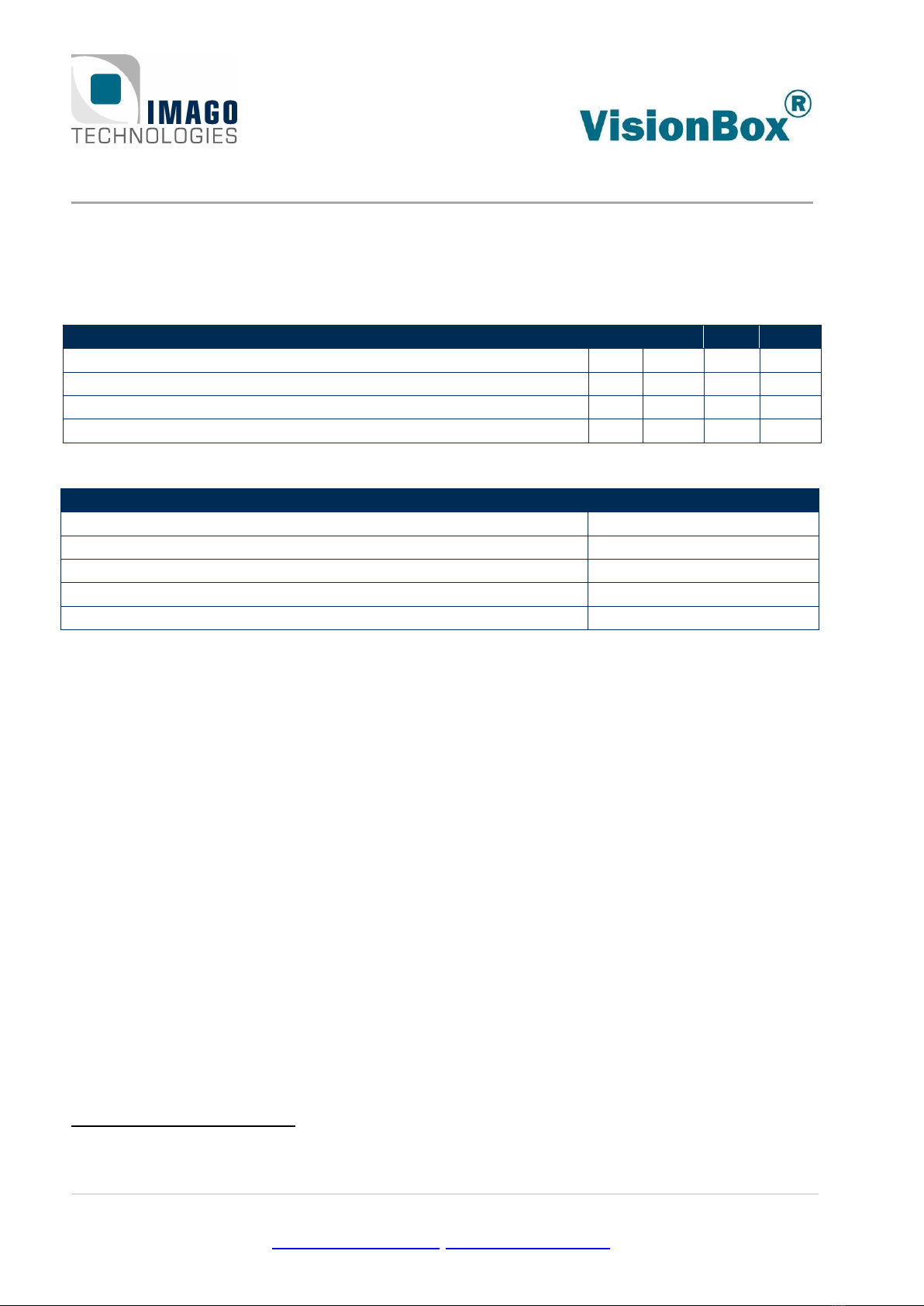
2.2 Configurations
The following table shows available features and interfaces for the VisionBox DAYTONA:
Jetson TX2
Main Storage
32 GB eMMC,
SD card slot
Ethernet
3× 1000 Mbit/s
USB
2× USB 3.0
1x micro USB service port
Dig. I/Os
8× IN / 8× OUT
RS-422
3× IN, 3× OUT (option)
Display
1× DisplayPort
Wireless
Wi-Fi, Bluetooth
Additional Options
M.2 SATA SSD,
M.2 LTE / 4G
Table 1: Feature overview
Please also ask for special OEM configurations.

3 Technical Data Page 8 / 22
IMAGO Technologies GmbH
Strassheimer Str. 45; 61169 Friedberg - Germany; Tel. +49 6031-6842611
info@imago-technologies.com; www.imago-technologies.com
3Technical Data
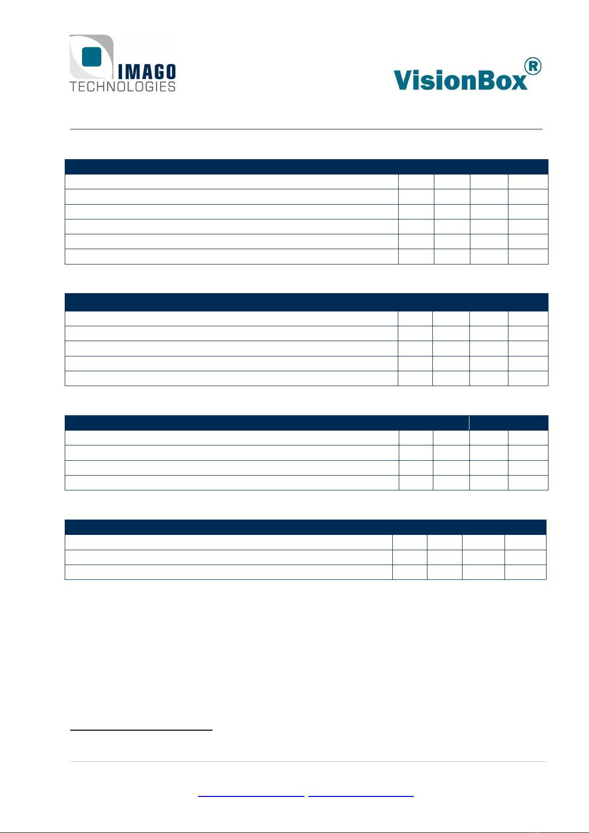
3.1 Operating Conditions
Power Supply:
Parameter
Min.
Typ.
Max.
Unit
Supply Voltage
20
24
28
V
Typical Power Consumption1
7
24
W
Continuous Supply Current Limit
3
A
Real-Time-Clock Backup Supply Duration (Ultracapacitor)
2
days
Environment:
Parameter
Value
Operating Temperature Range [°C]
+5 … +50
Operating Humidity [%, relative, non-condensing]
5 … 85
Storage Temperature [°C]
-10 … +70
Storage Humidity [%, relative, non-condensing]
5 … 95
Device Weight [g]
1300
Note: The maximum allowed temperature is influenced by the actual hardware configuration,
the system workload and the mounting situation. The temperature range should be veri-
fied for each application.
Note: The heat sink can transfer more heat in upright mounting position.
Note: Due to the lifetime of electronic components (laws of physics say: if the average operating
temperature is increased by 7°C, the lifespan of an electronic component will be cut in
half), we recommend not to operate the device permanently under the maximum possible
temperature and instead use a lower than max temperature. It is recommended that the
application software regularly checks internal temperatures.
1
The listed range applies to different CPU / GPU workloads while using DisplayPort and a single Gigabit Ethernet con-
nection. The use of additional interfaces and supply of connected USB and PoE devices is not accounted for.
3 Technical Data Page 9 / 22
IMAGO Technologies GmbH
Strassheimer Str. 45; 61169 Friedberg - Germany; Tel. +49 6031-6842611
info@imago-technologies.com; www.imago-technologies.com
RS-422:
Parameter
Min.
Typ.
Max.
Unit
Receiver Input Hysteresis
45
mV
Receiver Input Offset
3.3
V
Receiver Data Rate
10
Mbps
Differential Driver Output, RL= 100 Ω
2
V
Differential Driver Output, Open
3.3
V
Differential Driver Data Rate
2
Mbps
Digital Input:
Parameter
Min.
Typ.
Max.
Unit
Input Voltage
24
30
V
High Level Current Threshold
1
5
mA
Maximum Current Internal Limited
6
21
mA
Threshold Voltage
6
11
V
Signal Frequency
5
MHz
Digital Output:
Parameter
Min.
Typ.
Max.
Unit
Common VCC Supply Voltage
30
V
Output Current, Saturated Operation (VCE < 1 V)
10
20
mA
Turn-On Time (24 V Common VCC, 10 mA)
5
µs
Turn-Off Time (24 V Common VCC, 10 mA)
15
µs
Ethernet with 2× PoE (IEEE 802.3af/at):
Parameter
Min.
Typ.
Max.
Unit
PoE Output Voltage
54
V
PoE Class Support
0
4
Total PoE Supply Power for all Four Ports2
31
W
2
For example, two class 3 devices or one class 4 device can be powered simultaneously.

4 Power Connector and LEDs Page 11 / 22
IMAGO Technologies GmbH
Strassheimer Str. 45; 61169 Friedberg - Germany; Tel. +49 6031-6842611
info@imago-technologies.com; www.imago-technologies.com
4Power Connector and LEDs
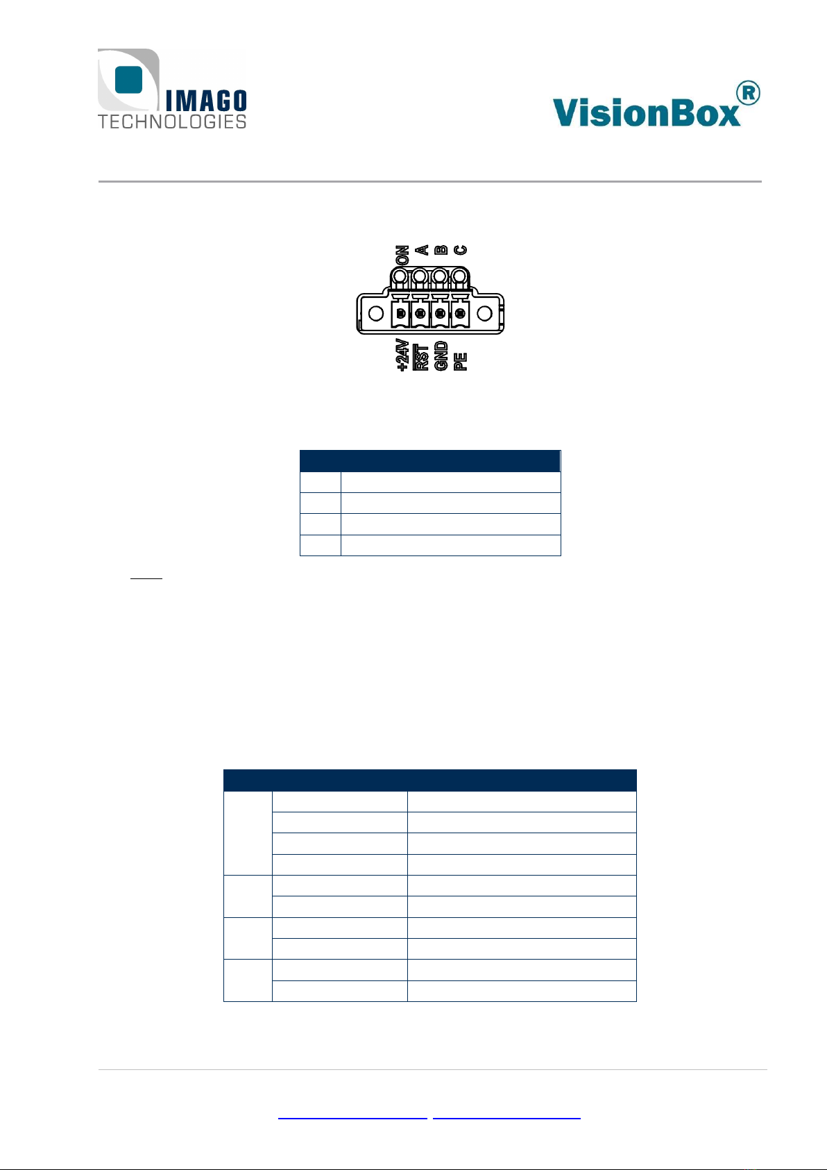
Figure 2: Power connector with system LEDs
4.1 Power Connector
Pin
Function
1
24 V power supply
2
Reset input
3
GND
4
Shield / housing connection
Table 2: Power connector
The
RST
terminal can be used to reset the VisionBox during operation. While the signal is pulled
to GND, the VisionBox is held in reset state. Leaving the signal floating is the default mode for
normal operation.
Mating external plug component: Phoenix Contact MC 1,5/4-STF-3,5 (order no. 1847071)
4.2 System LEDs
The VisionBox has four main system LEDs. These LEDs are dual color (bicolor) types. The behavior
of LEDs A, B and C can be controlled by software.
LED
Color
Function (green)
On
Green
Power on
Green blinking
USB recovery mode
Orange
System reset or power down
Red
FPGA configuration error
A
Green
User LED 0
Red
User LED 1
B
Green
User LED 2
Red
User LED 3
C
Green
User LED 4
Red
User LED 5
Table 3: LED values
5 Interfaces Page 12 / 22
IMAGO Technologies GmbH
Strassheimer Str. 45; 61169 Friedberg - Germany; Tel. +49 6031-6842611
info@imago-technologies.com; www.imago-technologies.com
5Interfaces
5.1 Ethernet
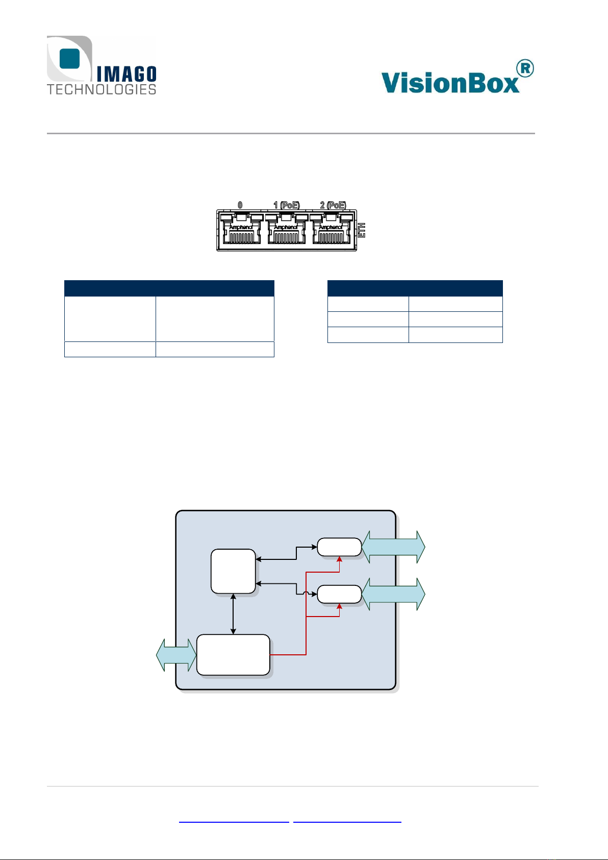
Figure 3: Ethernet connector
Left LED
State
Blinking
Traffic
(only with 100 or
1000 Mbit/s link)
Off
No traffic
Right LED
Link Speed
Green
1000 Mbit/s
Orange
100 Mbit/s
Off
10 Mbit/s
5.1.1 Power-over-Ethernet
Ethernet ports 1 and 2 can provide power to PoE devices using the IEEE 802.3af/at standard.
5.1.2 Trigger-over-Ethernet
The ToE feature adds support for the GigE Vision Action Command on Ethernet ports 1 and 2. It
can be used to trigger cameras over Ethernet in real time. The GigE specification allows sending
these messages by a different device, distinct from the primary application, which normally runs
on the main CPU. A sideband interface allows the Real-Time Communication Controller to intro-
duce packets into the network:
VisionBox
Intel I210
CPU
Real-Time
Communication
Controller
Intel I210
Sideband
Interface
1000 Mbit/s
with PoE and ToE
1000 Mbit/s
with PoE and ToE
Setup
PCIe
PCIe
I/O
Figure 4: GigE real-time trigger diagram
Two different Action Commands can be defined by the application. Please note that Action Com-
mands don’t belong to any port. All Action Commands are broadcast on all four ports.

5 Interfaces Page 13 / 22
IMAGO Technologies GmbH
Strassheimer Str. 45; 61169 Friedberg - Germany; Tel. +49 6031-6842611
info@imago-technologies.com; www.imago-technologies.com
5.2 USB 3.0
Figure 5: USB 3.0 port
The VisionBox provides two USB 3.0 type A ports. The supported maximum speed is 5 Gb/s. Based
on the USB specification, each port can deliver 900 mA.
5.3 Micro USB Service Port
Figure 6: Micro USB service port
The micro USB service port only supports device mode operation. There are two use cases:
•If a PC is connected to the micro USB port during power on, the VisionBox enters USB re-
covery mode. This is indicated by a green blinking ON LED. Only use this mode if advised
by IMAGO. Do not try to flash the Jetson OS image provided by NVIDIA!
•If a PC is connected after the VisionBox has already booted, the following USB device func-
tions are supported by the Linux OS:
oEthernet: Provides SSH access, used by NVIDIA SDK manager for installation of SDK
components.
oUART/Serial interface
oUSB Mass Storage device
Important note:
The micro USB signals are shared with the first USB 3.0 port. The USB signals are internally
switched to the micro USB port if a host is connected and providing the 5V USB supply voltage.
Therefore, any devices connected to the USB 3.0 port 0 should be removed before plugging or
unplugging the micro USB host cable during runtime. Otherwise, the integrated USB host control-
ler may fail to operate.
5 Interfaces Page 14 / 22
IMAGO Technologies GmbH
Strassheimer Str. 45; 61169 Friedberg - Germany; Tel. +49 6031-6842611
info@imago-technologies.com; www.imago-technologies.com
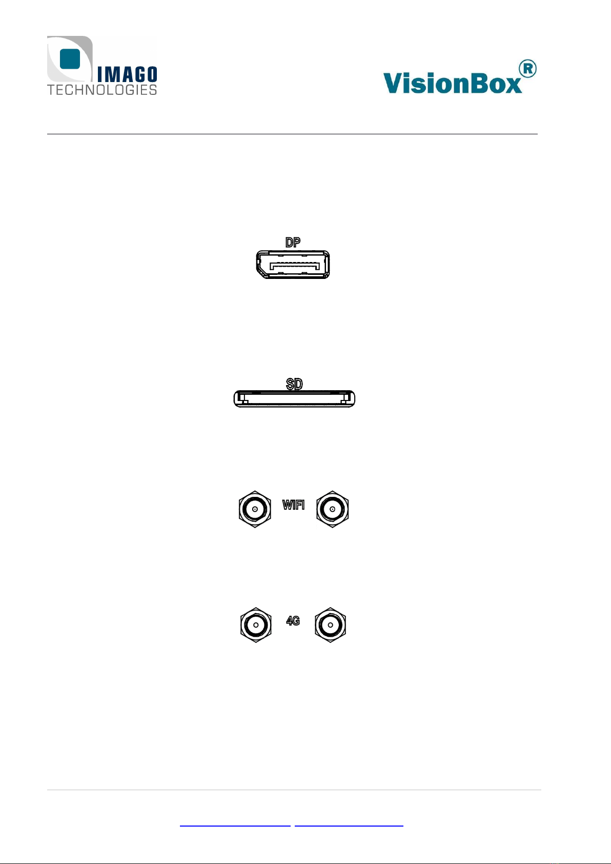
5.4 DisplayPort
The DisplayPort 1.2a interface supports a link speed of up to 5.4 Gbps with 1, 2 or 4 lanes. The
maximum supported resolution is 3840 × 2160 at 60 Hz. To connect the DP Port with a DVI, HDMI
or VGA monitor, an active adapter is needed.
Figure 7: DP connector
5.5 SD Card
The SD card socket supports SDHC and SDXC memory cards with a maximum interface speed of
104 MB/s (UHS-I).
Figure 8: SD card socket
5.6 Wi-Fi and Bluetooth
Two SMA connectors are shared between Wi-Fi and Bluetooth. Two antennas are used for
IEEE802.11n/ac Wi-Fi modes. The connectors are of type female RP-SMA.
Figure 9: Wi-Fi SMA connectors
5.7 4G / LTE Modem
The VisionBox can optionally be equipped with a 4G / LTE modem. One or two female SMA con-
nectors are then available.
Figure 10: 4G / LTE connectors
5 Interfaces Page 15 / 22
IMAGO Technologies GmbH
Strassheimer Str. 45; 61169 Friedberg - Germany; Tel. +49 6031-6842611
info@imago-technologies.com; www.imago-technologies.com
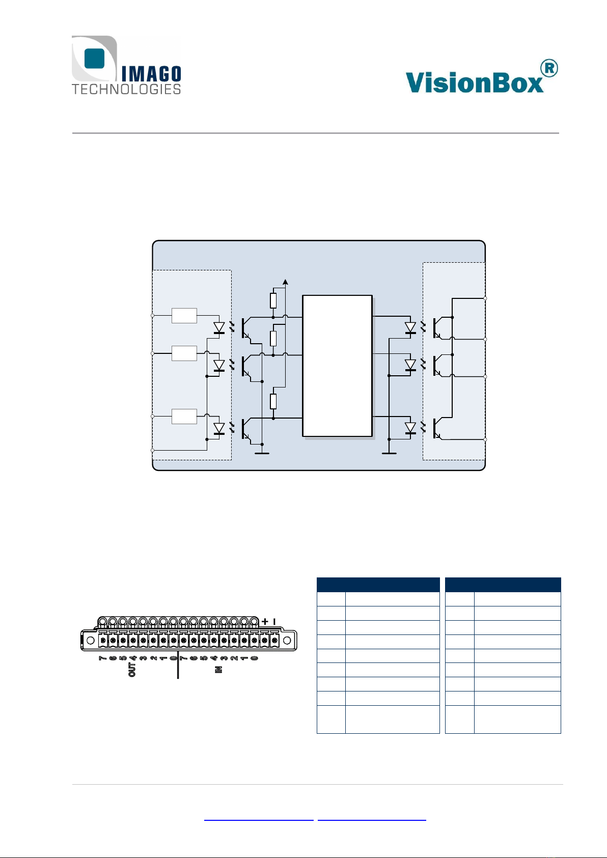
5.8 Digital I/O
The digital I/O interface provides an input and an output group, each containing eight signals. The
input group is electrically isolated from the output group. Both groups are also isolated from oth-
er VisionBox circuits and interfaces.
The following illustration shows the corresponding electrical equivalent circuit:
Galvanic
isolation
OUT 0
+ / VCC
OUT 7
OUT 1
Galvanic isolation
- / GND
Current
Limit
Current
Limit
Current
Limit
...
...
...
IN 0
IN 1
IN 7
Real-Time
Communication
Controller
(FPGA)
VisionBox
...
...
...
Figure 11:Simplified digital I/O circuit
The input group requires an external connection of a shared GND reference. For the output
group, the user must provide a supply voltage to the VCC pin which is used by all output signals.
Every input and output have an LED to show the current state of the channel.
The connector arrangement is shown below:
Figure 12: Digital I/O connector
Pin
Function
1
OUT 7
2
OUT 6
3
OUT 5
4
OUT 4
5
OUT 3
6
OUT 2
7
OUT 1
8
OUT 0
17
+ / Common VCC
of outputs
Pin
Function
9
IN 7
10
IN 6
11
IN 5
12
IN 4
13
IN 3
14
IN 2
15
IN 1
16
IN 0
18
- / Common
GND of inputs
Table 4: Pin assignment dig. I/O
Mating external plug component: Phoenix Contact MC 1,5/18-STF-3,5 (order no. 1847288)
5 Interfaces Page 16 / 22
IMAGO Technologies GmbH
Strassheimer Str. 45; 61169 Friedberg - Germany; Tel. +49 6031-6842611
info@imago-technologies.com; www.imago-technologies.com
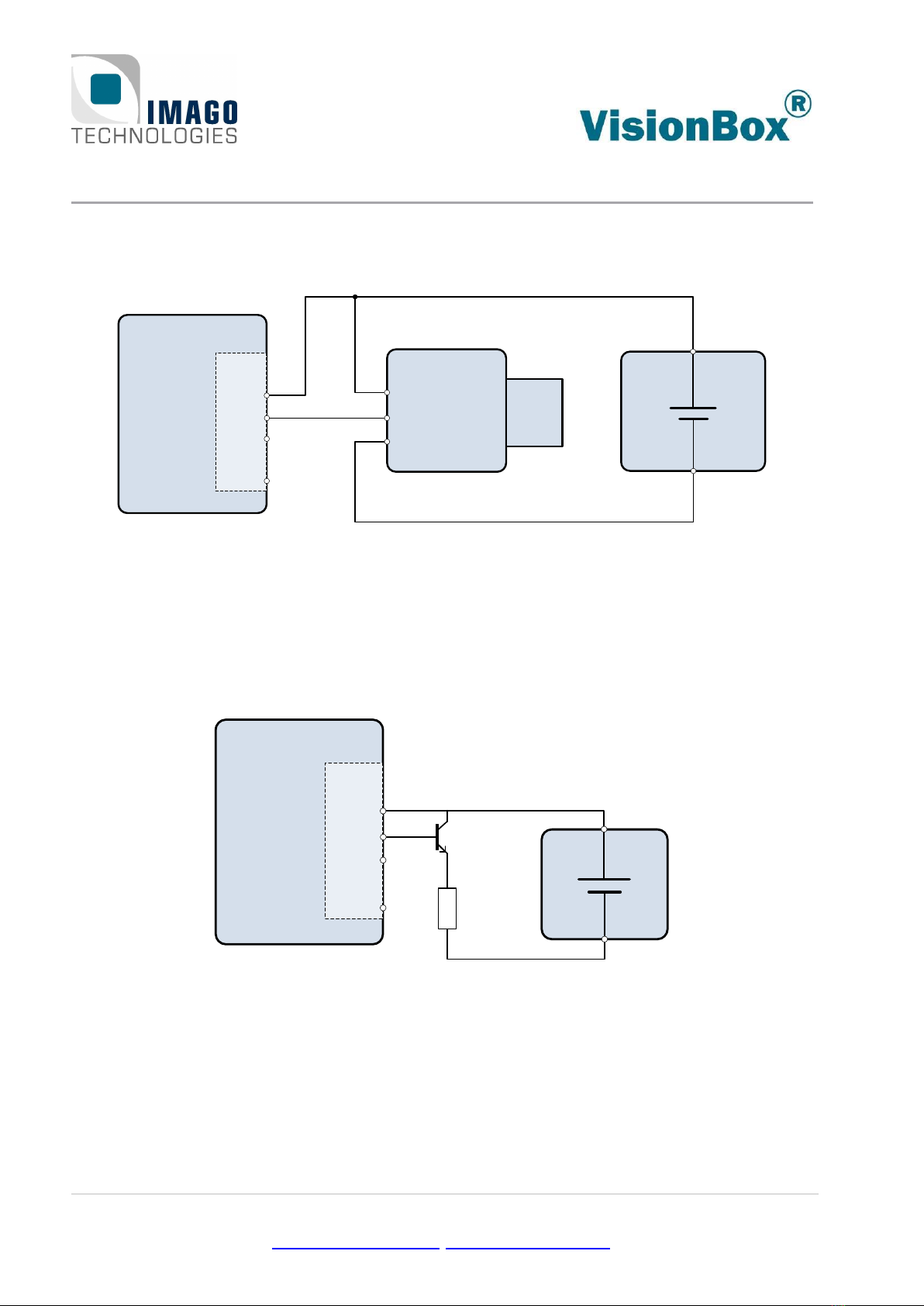
Example 1: Connecting a camera to a digital output
VisionBox
Digital
Outputs Power
Supply
OUT 0
+ / VCC Power VCC
GND
Trigger IN
Camera +
-
OUT 1
...
OUT 7
Figure 13: Digital output example 1
Depending on the voltage and isolation requirements of the application, the VisionBox can be
powered from the same or from a different power supply.
Example 2: Connecting an external transistor for higher current capability
Power
Supply
+
-
VisionBox
Digital
Outputs
OUT 0
+ / VCC
OUT 1
...
OUT 7
Figure 14: Digital output example 2
5 Interfaces Page 17 / 22
IMAGO Technologies GmbH
Strassheimer Str. 45; 61169 Friedberg - Germany; Tel. +49 6031-6842611
info@imago-technologies.com; www.imago-technologies.com
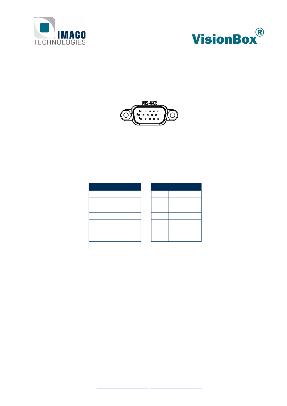
5.9 RS-422
The RS-422 connector can be used to trigger cameras by using external sensors or incremental
encoders. Logical trigger conditions can be implemented within the FPGA.
Figure 15: D-Sub 15-HD connector
For example, the AMPHENOL connector L77HDE15SOL2 can be used to make a connection to the
VisionBox.
Pins #5 and #15 provide a 5 V / 12 V power supply for RS-422 encoders.
Three RS-422 input signals and three RS-422 output signals are available:
Pin
Function
1
In1-
2
In2-
3
Out2-
4
Out1-
5
+5 V
6
GND
7
In1+
8
In2+
Pin
Function
9
Out2+
10
Out1+
11
In0+
12
In0-
13
Out0+
14
Out0-
15
+12 V
Table 5: RS-422 pin assignment
A “Fail-Safe” circuit is used for the input signals to put unconnected terminals into a defined state
(logic high).
6 Internal Connectors Page 18 / 22
IMAGO Technologies GmbH
Strassheimer Str. 45; 61169 Friedberg - Germany; Tel. +49 6031-6842611
info@imago-technologies.com; www.imago-technologies.com
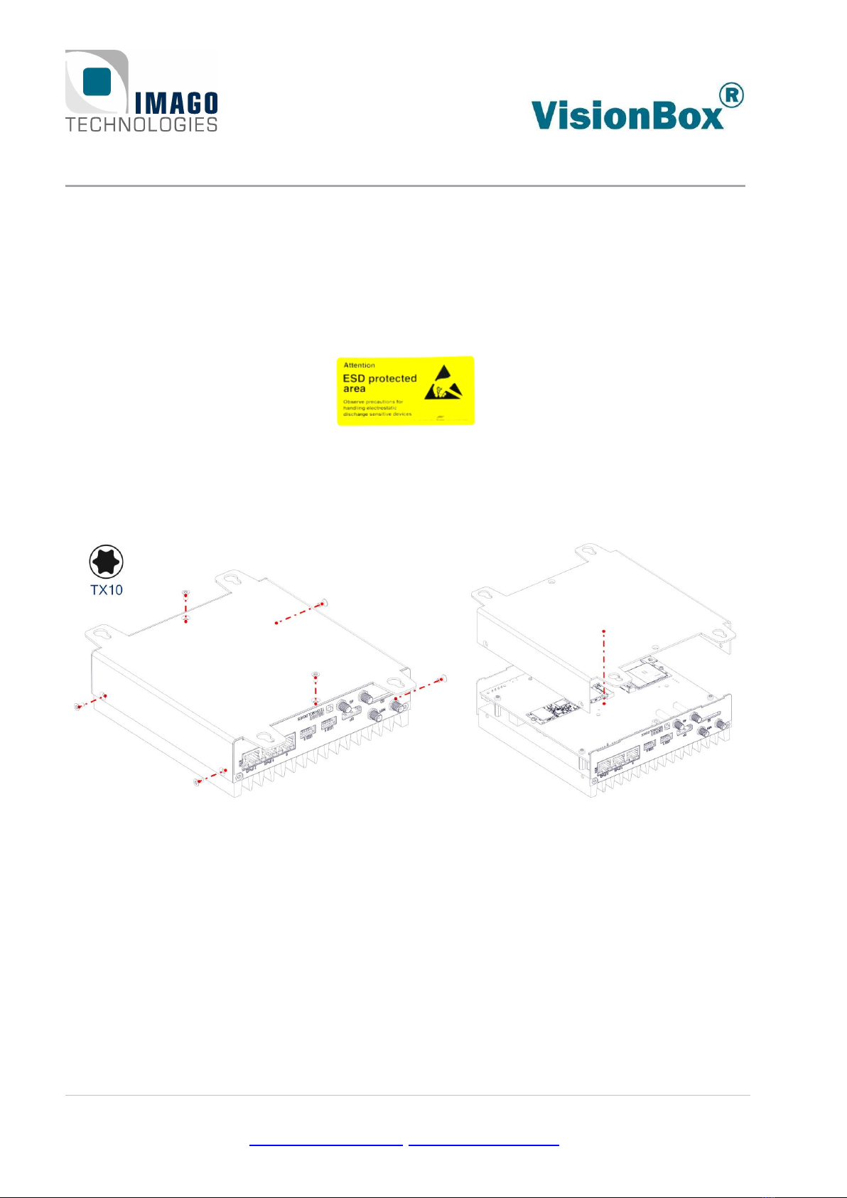
6Internal Connectors
The removable cover allows access to the following internal components:
•M.2 socket for SATA SSD
•M.2 socket for LTE / 4G modem
•Nano SIM socket
Before removing the housing cover, the VisionBox must be completely disconnected and the
environment must be protected against ESD.
Figure 16:Removing the housing cover
6 Internal Connectors Page 19 / 22
IMAGO Technologies GmbH
Strassheimer Str. 45; 61169 Friedberg - Germany; Tel. +49 6031-6842611
info@imago-technologies.com; www.imago-technologies.com
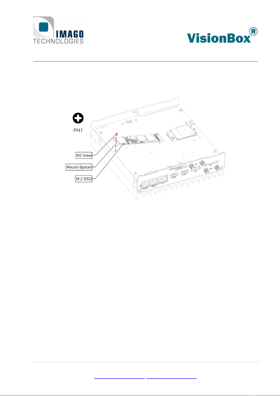
6.1 M.2 SSD
The M.2 connector with type M keying notches can be used for adding an SSD to the VisionBox. It
supports 80 mm modules and 3 Gbit/s SATA signaling. PCI Express signaling is not supported.
Figure 17: M.2 SSD

6 Internal Connectors Page 20 / 22
IMAGO Technologies GmbH
Strassheimer Str. 45; 61169 Friedberg - Germany; Tel. +49 6031-6842611
info@imago-technologies.com; www.imago-technologies.com
6.2 M.2 LTE Modem
The M.2 connector with type B keying notches allows the use of 4G / LTE modems with a USB 2.0
interface. A module length of 42 mm is supported.
Figure 18: M.2 LTE modem
6.3 Nano SIM
The Nano SIM socket is connected to the M.2 connector for direct use by the LTE modem.
Figure 19: Nano SIM card
Table of contents


