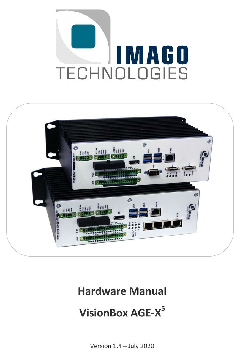
IMAGO VisionBox AGE-X5 User manual

Hardware Manual
VisionBox AGE-X5
Version 1.8 –2023

Contents Page 2 / 33
IMAGO Technologies GmbH
Strassheimer Str. 45; 61169 Friedberg - Germany; Tel. +49 6031-6842611
info@imago-technologies.com; www.imago-technologies.com
Contents
1Handling and Safety Instructions ............................................................ 3
2Introduction ................................................................................................. 4
2.1 Concept............................................................................................................................... 5
2.2 Configurations ................................................................................................................... 7
2.3 Block Diagram.................................................................................................................... 8
3Technical Data............................................................................................11
3.1 Processors ....................................................................................................................... 11
3.2 Operating Conditions...................................................................................................... 12
3.3 Dimensions....................................................................................................................... 16
4Power Connector and LEDs.....................................................................17
4.1 Power Connector ............................................................................................................. 17
4.2 System LEDs.................................................................................................................... 17
5Interfaces ....................................................................................................18
5.1 Ethernet Interface (Single).............................................................................................. 18
5.2 Ethernet Interface (Quad) ............................................................................................... 19
5.2.1 Power-over-Ethernet ........................................................................................................... 20
5.2.2 Trigger-over-Ethernet.......................................................................................................... 21
5.3 DisplayPort Monitor Interface ........................................................................................ 22
5.4 CFast ................................................................................................................................. 22
5.5 Digital I/O .......................................................................................................................... 23
5.6 RS-422 Interface............................................................................................................... 26
5.7 LED Controller and Camera Trigger.............................................................................. 27
5.7.1 LED Controller...................................................................................................................... 27
5.7.2 Camera Trigger.................................................................................................................... 28
5.8 Camera Link ..................................................................................................................... 29
5.8.1 Power-over-CameraLink..................................................................................................... 29
6Internal Connectors...................................................................................30
6.1 USB 2.0.............................................................................................................................. 30
6.2 SATA ................................................................................................................................. 31
6.3 CMOS Battery................................................................................................................... 31
7Accessories................................................................................................32
7.1 Third-party Components................................................................................................. 32
7.2 IMAGO Accessories ........................................................................................................ 32
8History .........................................................................................................33

Handling and Safety Instructions Page 3 / 33
IMAGO Technologies GmbH
Strassheimer Str. 45; 61169 Friedberg - Germany; Tel. +49 6031-6842611
info@imago-technologies.com; www.imago-technologies.com
1Handling and Safety Instructions
Depending on the operating conditions, the housing temperature can exceed 60 °C.
There is a risk of injury!
Handle with care! The housing, especially heat sinks can have sharp edges. There is
a risk of injury!
EMC conformity according to EN/IEC 61000-6-2:2005 is qualified for cable lengths ≤
30 m.
Electrostatic discharge at unshielded I/O connectors can lead to unexpected events
or data errors for the corresponding interface.
Electrical installation should be executed without power applied to the device and
connected devices.
Before installing expansion cards, make sure that the VisionBox AGE-X is discon-
nected from power.
Use appropriate ESD protection when changing components.
Only open if advised by IMAGO!
Warranty void if warranty seal is removed or broken.
Please take special note of the voltage range which may be applied to the device.
Otherwise, permanent damage to the device may result!
Air Circulation
When mounting the device within an enclosure, adequate space for air circulation
is required. The space above, below and at both sides should be at least 5 cm.
Avoid extreme environmental conditions and protect the VisionBox from dust,
humidity and heat.
Due to the characteristics and physical principles inside flash memory, SSDs have a
finite lifetime dictated by the number of write operations.
Therefore, take care of the regular write operations to prevent an early SSD dam-
age. Ask for the technical data of the used SSD and, if necessary, for support to
calculate the lifetime.
Inform the user of the system that SSDs are wear parts which must be renewed
regularly.

2 Introduction Page 4 / 33
IMAGO Technologies GmbH
Strassheimer Str. 45; 61169 Friedberg - Germany; Tel. +49 6031-6842611
info@imago-technologies.com; www.imago-technologies.com
2Introduction
Thank you very much for your interest in our VisionBox AGE-X. To get the most out of your purchase,
please take some time to read all the information given here thoroughly.
This VisionBox is optimized for cameras using the GigE Vision or Camera Link interface. For multi-camera
systems, not only several camera ports but also several integrated LED Controllers and digital I/Os allow a
compact setup without additional electronics. If you need more connectivity or a specific PCIe board, kind-
ly consult the other VisionBox alternatives.
The integrated Real-Time Communication Controller ensures proper timing between all devices, even
when using Windows or Linux operating systems. To avoid complex cabling, the cameras can be connected
through standard Ethernet cables. A single cable provides trigger, image data and power for each GigE
camera.
Thanks to its small size, powered by 24VDC and without fan, the AGE-X can be mounted into nearly every
machine, also as IP65 version for OEM quantities.
All components are available for several years in order to provide continuous delivery without changes.
The AGE-X-SDK can be used in C++ and .NET as well as with some third-party machine vision libraries to
enable an easy integration with your products and projects.
For series production, IMAGO delivers the AGE-X ready-to-run, including customer-specific SSD image,
qualified 3rd-party components and acceptance test.

2 Introduction Page 5 / 33
IMAGO Technologies GmbH
Strassheimer Str. 45; 61169 Friedberg - Germany; Tel. +49 6031-6842611
info@imago-technologies.com; www.imago-technologies.com
2.1 Concept
the philosophy of the Vision Box AGE-X series it is about a real-time communication controller with vision-
& automation-specific interfaces combined with an embedded Intel processor:
•6th, 7th and 10th generation Intel x86 processor
•Real-Time Communication Controller RTCC:
oControls vision- & automation-specific interfaces:
▪Digital I/Os
▪Encoder
▪Camera trigger
▪LED Strobe Controller
oContains functional units for controlling I/Os in real time:
▪Trigger unit: Creation of trigger signals, derived from other inputs (e.g. encoder)
▪I/O scheduler: applies values stored in a FIFO to outputs in real time (based on
trigger event, encoder position, or timer value)
▪Multiplexer: flexible connection of functional units
oOperates independently from the OS & the x86 processor
oEasy-to-use high-level API for C++, .NET and support by 3rd-party software tools
•4 types of models:
o4x 1GigE
▪Four GigE Vision cameras can be connected
▪Option PoE / ToE: Power-over-Ethernet / Trigger-over-Ethernet from RTCC with a
microsecond jitter
o4x 2.5GigE
▪Four GigE Vision cameras can be connected
oCamera Link
▪Two Camera Link Base cameras can be operated or one Camera Link Medium / Full
/ Deca camera
▪Support for Power-over-Camera-Link (PoCL)
o2x 5GigE and 2x 1GigE
▪Two 5GigE Vision cameras and two 1GigE Vision cameras can be connected. It’s al-
so possible to operate four 1GigE Vision cameras.
•Digital I/Os:
oIsolated
oStatus LEDs
oInputs up to 5 MHz with adjustable debouncing in RTCC. Communicated to x86 via inter-
rupt or polling
oOutputs up to 50 kHz / up to 1 A / up to 48 V
•x86 processor
oIntel processors
oWindows 10 IoT Enterprise

2 Introduction Page 6 / 33
IMAGO Technologies GmbH
Strassheimer Str. 45; 61169 Friedberg - Germany; Tel. +49 6031-6842611
info@imago-technologies.com; www.imago-technologies.com
oWindows 11 IoT Enterprise
1
oDebian GNU/Linux, optionally with PREEMPT_RT patch
•Housing
oPassive cooling
oAll interfaces on front panel
o24 VDC power input
oNo moving parts
oService hatch for access to USB 2.0 for dongle
•More vision & automation interfaces
oRS-422 inputs / outputs, e.g. for encoders
oLED controllers up to 6 A strobe / 0,5 A continuous
1
Windows 11 is only possible with 10th gen CPU

2 Introduction Page 7 / 33
IMAGO Technologies GmbH
Strassheimer Str. 45; 61169 Friedberg - Germany; Tel. +49 6031-6842611
info@imago-technologies.com; www.imago-technologies.com
2.2 Configurations
The following table shows available features and interfaces for the different models of the VisionBox AGE-
X5:
Model
4× 1GigE
4× 2.5GigE
2× 5GigE +
2× 1GigE
Camera Link
RAM
up to 32 GB2
Storage
CFast SSD
mSATA (optionally)
SATA 3.0 (optionally)
M.2 2280 M-key3
USB
4× USB 3.0 or 4× USB 3.14
Display
DP++ (max. resolution 4096x2304 @ 60Hz)
Ethernet (single)
1× 1GbE or 2.5GbE5
Camera Interface
4x 1GigE
4x 2.5GigE
2x 5GigE,
2x 1GigE
Camera Link with PoCL
2× Base or
1× Medium / Full / Deca
Additional Options
4× PoE / ToE
-
Dig. I/Os
8× IN / 8× OUT
optionally 16× IN / 16× OUT
LED Controller
2×, optionally 4×
2×
-
Camera Trigger
2×, optionally 4×
2×
-
Encoder / RS-422
Optionally 4× IN
Optionally 4× IN
3× IN / 3× OUT,
optionally additional 4× IN
Table 1: Feature overview
Please also ask for special OEM configurations.
2
64 GB possible with 10th gen CPU
3
M.2 socket is only present on 10th gen CPU models
4
USB 3.1 is only provided with 10th gen CPU models
5
2.5GbE is only provided with 10th gen CPU models

2 Introduction Page 8 / 33
IMAGO Technologies GmbH
Strassheimer Str. 45; 61169 Friedberg - Germany; Tel. +49 6031-6842611
info@imago-technologies.com; www.imago-technologies.com
2.3 Block Diagram
Real Time
Communication
Controller
(FPGA)
VISION
COMPUTER
X86
Multi Core
Processor
PCIe
CFast
DisplayPort
8/8
digital IO
2x LED
2x Trigger
Ethernet (single)
2.5" SATA
4x USB 3.0
2x USB 2.0
(internal)
Encoder Input
RS422
8/8 digital IO or
2x LED + 2x Trigger
mSATA or mini
PCIe
GigE
Camera
4x
1GigE
(4x Intel
I210)
GigE
Camera
GigE
Camera
GigE
Camera
Trigger over Ethernet
PoE
M.2 2280 (M key)
4x PCIe x1
Figure 1: Block diagram: 4× 1GigE

2 Introduction Page 9 / 33
IMAGO Technologies GmbH
Strassheimer Str. 45; 61169 Friedberg - Germany; Tel. +49 6031-6842611
info@imago-technologies.com; www.imago-technologies.com
Real Time
Communication
Controller
(FPGA)
VISION
COMPUTER
X86
Multi Core
Processor
PCIe
CFast
DisplayPort
8/8
digital IO
2x LED
2x Trigger
Ethernet (single)
2.5" SATA
4x USB 3.0
2x USB 2.0
Encoder Input
RS422
8/8 digital IO or
2x LED + 2x Trigger
mSATA or mini
PCIe
GigE
Camera
2x 5GigE +
2x 1GigE
or
4x 2.5GigE
GigE
Camera
GigE
Camera
GigE
Camera
M.2 2280 (M key)
4x PCIe x1
Figure 2: Block diagram: 2× 5GigE + 2× 1GigE or 4x 2.5GigE

2 Introduction Page 10 / 33
IMAGO Technologies GmbH
Strassheimer Str. 45; 61169 Friedberg - Germany; Tel. +49 6031-6842611
info@imago-technologies.com; www.imago-technologies.com
Real Time
Communication
Controller
(FPGA)
VISION
COMPUTER
X86
Multi Core
Processor
PCIe
CFast
DisplayPort
8/8
digital IO
Ethernet (single)
2.5" SATA
4x USB 3.0
2x USB 2.0
8/8
digital IO
mSATA or mini
PCIe
CL1
Camera Link
Grabber with
PoCL
CL0
Encoder Input/
Output RS422
PCIe x4
Trigger (CC)
M.2 2280 (M key)
Figure 3: Block diagram: Camera Link

3 Technical Data Page 11 / 33
IMAGO Technologies GmbH
Strassheimer Str. 45; 61169 Friedberg - Germany; Tel. +49 6031-6842611
info@imago-technologies.com; www.imago-technologies.com
3Technical Data
3.1 Processors
The following processors of 6th and 7th generation are currently supported:
Celeron G3900
i5-6500TE
i7-6700TE
i5-7500T
i7-7700
Nominal Frequency
2.8 GHz
2.3 GHz
2.4 GHz
2.7 GHz
3.6 GHz
Turbo Frequency
- - -
3.3 GHz
3.4 GHz
3.3 GHz
4.2 GHz
Cores / Threads
2 / 2
4 / 4
4 / 8
4 / 4
4 / 8
TDP
51 W6
35 W
35 W
35 W
65 W
Table 2: Processor overview 6th and 7th generation
The following processors of 10th generation are currently supported:
Pentium G6400E
i5-10500TE
i7-10700TE
i5-10500E
i7-10700E
Nominal Frequency
4.0 GHz
2.3 GHz
2.0 GHz
3.1 GHz
2.9 GHz
Turbo Frequency
- - -
3.7 GHz
4.4 GHz
4.2 GHz
4.5 GHz
Cores / Threads
2 / 4
6 / 12
8 / 16
6 / 12
8 / 16
TDP / Max. power
in turbo
58 W7/ -
35 W / 92 W
35 W / 124 W
65 W / 134 W
65 W / 224 W
Table 3: Processor overview 10th generation
6
Actual power values for this CPU are much lower than Intel specification.
7
Actual power values for this CPU are much lower than Intel specification.

3 Technical Data Page 12 / 33
IMAGO Technologies GmbH
Strassheimer Str. 45; 61169 Friedberg - Germany; Tel. +49 6031-6842611
info@imago-technologies.com; www.imago-technologies.com
3.2 Operating Conditions
Power supply:
Parameter
CPU
Celeron G3900
i5-6500TE
i7-6700TE
i5-7500T
i7-7700
Pentium G6400E
i5-10500TE
i7-10700TE
i5-10500E
i7-10700E
Uni
t
Power supply
18..30
21…30
18..30
21…30
V
Power Consumption8
(at TDP workload)
32
65
105
61
65
68
106
111
W
Power Supply Cur-
rent Rating9
(Peak current)
1.4
3.2
5.3
2.5
5.4 / 3.710
7.8 / 3.811
6.3
8.9
A
Continuous Supply
Current Limit12
8
A
Environment:
Parameter
Value
Unit
Operating Temperature for Intel CPU 6th generation
+5 … +45
°C
Operating Temperature for Intel CPU 7th generation
+5 … +40
°C
Operating Temperature for Intel CPU 10th generation
+5 … +45
°C
Operating Humidity, relative, non-condensing
5 … 85
%
Storage Temperature
-10 … +70
°C
Storage Humidity, relative, non-condensing
5 … 95
%
Device Weight
2.4
kg
Note: The maximum allowed temperature is influenced by the actual hardware configuration, the system
workload and the mounting situation. The temperature range should be verified for each applica-
tion.
Note: The heat sink can transfer more heat in upright mounting position.
Note: Due to the lifetime of electronic components, we recommend not to operate the device perma-
nently under the maximum possible temperature and instead use a lower than max temperature.
Laws of physics say: if the average operating temperature is increased by 7°C, the lifespan of an
8
Measured with CPU at TDP workload and without external devices except 1× Ethernet and DP.
9
Measured with CPU at full workload; 24 V supply voltage; no external devices except 1× Ethernet link at 1000
Mbit/s. This value does not account for additional current drawn by interfaces like 4× Ethernet or for the supply of
LED units and PoE / PoCL / USB devices.
10
Power limit for turbo mode set to 53W in BIOS.
11
Power limit for turbo mode set to 53W in BIOS.
12
Certain possible usage combinations like simultaneous PoE / PoCL / USB device supply and active LED output can
lead to continuous excess of this value, which must be avoided by the user.

3 Technical Data Page 13 / 33
IMAGO Technologies GmbH
Strassheimer Str. 45; 61169 Friedberg - Germany; Tel. +49 6031-6842611
info@imago-technologies.com; www.imago-technologies.com
electronic component will be divided in half! Following are common scenarios in industrial applica-
tions:
•Multiple devices are mounted inside an electrical cabinet
➔The cabinet itself is equipped with an air conditioner.
•In a large electrical cabinet, a single device is mounted with other (low heat-producing) de-
vices
➔It is enough when a fan provides air circulation inside the cabinet.
•It is recommended that the application software regularly checks internal temperatures.

3 Technical Data Page 14 / 33
IMAGO Technologies GmbH
Strassheimer Str. 45; 61169 Friedberg - Germany; Tel. +49 6031-6842611
info@imago-technologies.com; www.imago-technologies.com
Digital Input:
Parameter
Min.
Typ.
Max.
Unit
Input voltage range
0
30
V
Input current range (limited by internal circuit)
0
21
mA
Threshold Voltage
Standard
6
11
V
TLL-compatible (option)13
1.8
2.4
Threshold current
1
5
mA
Input delay
250
ns
Digital Output:
Parameter
Min.
Typ.
Max.
Unit
Common VCC Supply Voltage (VCC - VOUT)
0
30
V
Output Current, Saturated Operation (VCC - VOUT) < 1 V
10
mA
Turn-On Time (24 V Common VCC, 10 mA)
5
µs
Turn-Off Time (24 V Common VCC, 10 mA)
15
µs
13
TTL-compatible option is only available for the second I/O module

3 Technical Data Page 15 / 33
IMAGO Technologies GmbH
Strassheimer Str. 45; 61169 Friedberg - Germany; Tel. +49 6031-6842611
info@imago-technologies.com; www.imago-technologies.com
RS-422
14
(Encoder):
Parameter
Min.
Typ.
Max.
Unit
Receiver Input Hysteresis
45
mV
Receiver Input Offset
3.3
V
Receiver Data Rate
10
Mbps
LED Controller:
Parameter15
Min.
Typ.
Max.
Unit
Strobe Current Range
0.05
6
A
Strobe Current Step Size
30
mA
Maximum Continuous Current (VSupply=28 V, VLoad=24 V)
0.5
A
Minimum Flash Duration @ 2 A
10
µs
Flash Duration Step Size
1
µs
Turn-on delay (6 A)
3
µs
Turn-on delay (100 mA)
80
µs
Turn-off Delay (6 A)
2
µs
Turn-off Delay (100 mA)
50
µs
Camera Trigger:
Parameter
Min.
Typ.
Max.
Unit
ACQ TRG High Voltage
24
V
ACQ TRG Low Voltage
0.5
V
ACQ TRG High Side Current
20
mA
ACQ TRG Maximum Low Side Sink Current
100
mA
Ethernet with 4× PoE Option (IEEE 802.3af/at):
Parameter
Min.
Typ.
Max.
Unit
PoE Output Voltage
53
V
PoE Class Support
0
4
Total PoE Supply Power for all Four Ports16
55
W
14
A “Fail-Safe” circuit is used for the input signals to put unconnected terminals into a defined state.
15
The maximum current and strobe timing limits are calculated by the software, depending on the used parameters.
16
For example, two class 4 devices or four class 3 devices can be powered simultaneously.

3 Technical Data Page 16 / 33
IMAGO Technologies GmbH
Strassheimer Str. 45; 61169 Friedberg - Germany; Tel. +49 6031-6842611
info@imago-technologies.com; www.imago-technologies.com
3.3 Dimensions
Figure 4: Housing dimensions (in mm)

4 Power Connector and LEDs Page 17 / 33
IMAGO Technologies GmbH
Strassheimer Str. 45; 61169 Friedberg - Germany; Tel. +49 6031-6842611
info@imago-technologies.com; www.imago-technologies.com
4Power Connector and LEDs
4.1 Power Connector
Figure 5: Power plug
Pin
Function
+24V
24 V power supply
RST
Reset input, low active
GND
Ground
PE
Shield / housing connection
Table 4: Power connector
The
RST
terminal can be pulled to GND to reset the VisionBox during operation. A falling edge will trigger
the reset. Leaving the signal floating is the default mode for normal operation.
Phoenix Contact plug component: MC 1,5/4-STF-3,5 (order no. 1847071)
4.2 System LEDs
The computer has four main system LEDs. These LEDs are dual color (bicolor) types. The functionality of
the LED A, B and C can be changed by software.
Figure 6: Status LEDs
LED
Color
Function (green)
On
Green
Power On
Red
FPGA configuration error
Orange
blinking
Backup firmware is loaded
Orange
System shutdown or reset
A
Green
User LED 0
Red
User LED 1
B
Green
User LED 2
Red
User LED 3
C
Green
User LED 4
(default: SATA/CFAST activity)
Red
User LED 5
Table 5: System LED values

5 Interfaces Page 18 / 33
IMAGO Technologies GmbH
Strassheimer Str. 45; 61169 Friedberg - Germany; Tel. +49 6031-6842611
info@imago-technologies.com; www.imago-technologies.com
5Interfaces
This chapter describes the interfaces for the VisionBox AGE-X5.
5.1 Ethernet Interface (Single)
The single Ethernet interface is present for all hardware configurations.
•6th or 7th generation CPU: 1GbE (1000BASE-T)
•10th generation CPU: 2.5GbE (2.5GBASE-T)
Figure 7: Ethernet connector (single)
Assignment of the status LEDs:
Link state
Upper LED
Link down
Off
Link up, no traffic
On
Link up, traffic
Blinking
Table 6: Upper LED
Link speed
6th / 7th gen. CPU
10th gen. CPU
10 Mbit/s
Off
Off
100 Mbit/s
Green
Off
1000 Mbit/s
Orange
Green
2500 Mbit/s
-
Red
Table 7: Lower LED

5 Interfaces Page 19 / 33
IMAGO Technologies GmbH
Strassheimer Str. 45; 61169 Friedberg - Germany; Tel. +49 6031-6842611
info@imago-technologies.com; www.imago-technologies.com
5.2 Ethernet Interface (Quad)
The VisionBox AGE-X5 with Quad GigE is available in the following configurations:
•4×1GigE (1000BASE-T), optionally with PoE and ToE (see following sections)
•4×2.5GigE (2.5GBASE-T)
•2×5GigE (port 1, 2: NBASE-T) + 2×1GigE (port 3, 4: 1000BASE-T)
Figure 8: Ethernet connector
Link speed
Port configuration
4x 1GigE
4x 2.5GigE
2x 5GigE
2x 1GigE
10 Mbit/s
Off
Off
-
Off
100 Mbit/s
Off
Off
Green
Off
1000 Mbit/s
Green
Green
Green
Green
2500 Mbit/s
-
Green
Green
-
5000 Mbit/s
-
-
Off
-
Table 8: Upper LEDs
Link state
Port configuration
4x 1GigE
4x 2.5GigE
2x 5GigE
2x 1GigE
Link down
Off
Off
Off
Off
Link up, no
traffic
Off
On
On
On
Link up, traffic
Blinking
Blinking
Blinking
Blinking
Table 9: Lower LEDs
For the 5GigE version, there are two additional status LEDs in the front panel indicating a 5000 Mb/s link
for ports 1 and 2:
Figure 9: 5GigE status LEDs

5 Interfaces Page 20 / 33
IMAGO Technologies GmbH
Strassheimer Str. 45; 61169 Friedberg - Germany; Tel. +49 6031-6842611
info@imago-technologies.com; www.imago-technologies.com
5.2.1 Power-over-Ethernet
The optional PoE feature for the VisionBox AGE-X5 with 4×1GigE provides power to PoE enabled devices.
Four additional status LEDs signaling the power state are associated with the four ports:
Figure 10: Ethernet PoE LEDs
LED State
Description
Green blinking
Searching for PoE device
Green on
PoE device found and powered
Red blinking all LEDs
Error code
Red flash single LED
See ToE section below
Table 10: PoE LED state
Other manuals for VisionBox AGE-X5
1
Table of contents
Other IMAGO Network Hardware manuals
Popular Network Hardware manuals by other brands
ADC
ADC HiGain H2TU-C-319 List 4E Quick installation
Nexcom
Nexcom NSA 7160 Quick reference guide

Iomega
Iomega Ix2-200 - StorCenter Network Storage NAS... Release notes
Huawei
Huawei RRU3908 V2 Hardware description
Cypress Semiconductor
Cypress Semiconductor Nine-Output 3.3V Buffer CY2309NZ manual
Wegener
Wegener Unity Satellite Receiver Model Unity Synchronous Data... Installation & operation
