IMC 4 Series User manual
VR60 GLASS FROSTERS
INSTALLATION AND OPERATING MANUAL
PLEASE LEAVE WITH OPERATOR
VR60 Glass Froster
Series 4
Imperial Machine Company Limited
Unit 1, Abbey Road
Wrexham Industrial Estate
Wrexham LL13 9RF
Tel: +44 (0)1978 661155
Fax: +44 (0)1978 729990
Service Fax: +44 (0)1978 667766
Spares Fax: +44 (0)1978 667759
E-mail: info@imco.co.uk
Website: www.imco.co.uk
A34/055 R5 ECN 8917 January 2020

VR60 –GLASS FROSTER 2
EC DECLARATION OF CONFORMITY
(Guarantee of Production Quality)
We, Imperial Machine Company Limited of:
Unit 1, Abbey Road, Wrexham Industrial Estate, Wrexham, LL13 9RF
Declare under our sole responsibility that the following products
VR60
as described in the attached technical documentation, are in conformity with the protection
requirements of the Electromagnetic Compatibility Directive 2014/30/EU and manufactured in
accordance with harmonised standards EN 61000-6-1: 2001 Immunity and EN 61000-6-3: 2007
Emissions (plus product specific standards).
They also satisfy the essential health and safety requirements of the Low Voltage Directive
2014/95/EC and are manufactured in accordance with standards BS EN 60335-1 and BS EN
60335-24, and the relevant requirements of the Pressure Equipment Directive 2014/68/EU.
Approved by : E.Plumb, Engineering Manager -
Date: January 2020

VR60 –GLASS FROSTER 3
INDEX
INDEX ................................................................................................................... 3
WARRANTY ......................................................................................................... 4
DELIVERY ............................................................................................................ 4
SAMPLE RATING LABEL.................................................................................... 5
INTRODUCTION................................................................................................... 5
INSTALLATION .................................................................................................... 7
CHANGING AN LED LIGHT FITTING.................................................................. 8
CHANGING OPTION DOOR HANDLES .............................................................. 9
ELECTRICITY SUPPLY CONNECTION............................................................. 10
COMMISSIONING .............................................................................................. 10
CHANGING THE CONTROLLER SET POINT ................................................... 11
USING YOUR GLASS FROSTER ...................................................................... 11
ECO BUTTON FUNCTION ................................................................................. 12
CLEANING.......................................................................................................... 13
CHANGING SHELF POSITION .......................................................................... 13
MAINTENANCE.................................................................................................. 14
DO’S AND DON’TS ............................................................................................ 15
ORDERING SPARE PARTS............................................................................... 16
END OF LIFE DISPOSAL................................................................................... 16
MATERIAL CONTENT........................................................................................ 16
WIRING DIAGRAM............................................................................................. 17
SPARES LIST DRAWING 1 ............................................................................... 18
SPARES LIST DRAWING 2 ............................................................................... 19
SPARES LIST ..................................................................................................... 20
NOTES................................................................................................................ 21
VR60
–
GLASS FROSTER
4
WARRANTY
These Glass Froster’s are guaranteed by IMC for 2 years from the date of
purchase from IMC, or from one of its stockists, dealers or distributors. The
guarantee is limited to the replacement of faulty parts or products and excludes
any consequential loss or expense incurred by the purchaser. Defects which
arise from faulty installation, inadequate maintenance, incorrect use, connection
to the wrong electricity supply, or fair wear and tear, are not covered by the
guarantee.
The guarantee applies in this form to installations within the United Kingdom.
Export units carry 2 years “parts only”warranty.
Please observe these instructions carefully.
DELIVERY
The packaged machine consists of:
VR60 Glass Froster containing:
Shelf (Full size)
Shelf (base ½ size)
Shelf clips
Sets of keys
2
1
8
2
Instruction Booklet 1
Please notify both the carrier and the supplier within three days of receipt if
anything is missing or damaged.
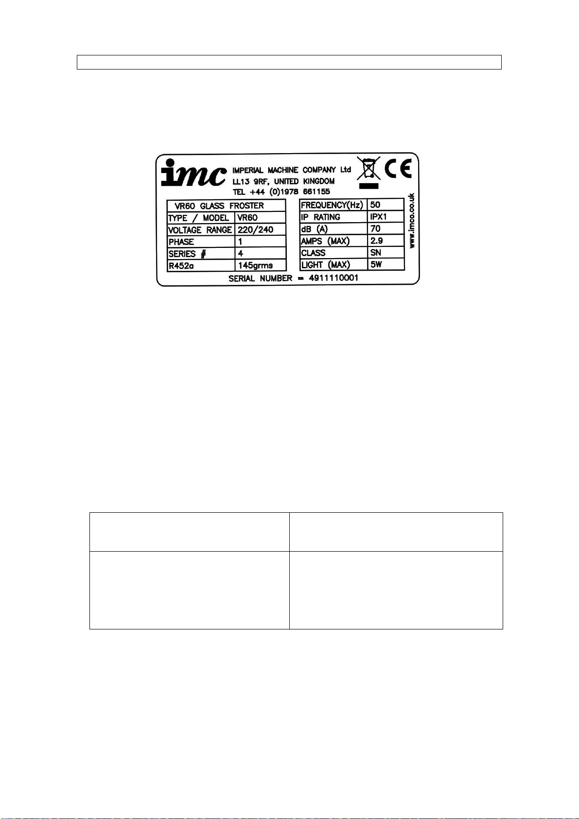
Check that the correct machine has been supplied and that the voltage, marked
on the rating plate, is suitable for the supply available. The rating plate is
located internally on the right hand side of the unit.
VR60
–
GLASS FROSTER
5
SAMPLE RATING LABEL
INTRODUCTION
The VR60 range is a back-bar or under-bar glass froster designed for the
frosting and storage of glasses.
The following quantity of standard pint glasses can be held in each unit:
Glass Froster Capacity
(Standard Pint Size Glass)
VR60 (900h x 600w x 500d)
VR60 (800h x 600w x 500d)
50
50

VR60
–
GLASS FROSTER
6
VR60 Dimensions:
MODEL
X
Y
V
R
60
900mm
500
900
V
R
60 8
0
0
mm
500
8
0
0
X mm
Y mm
600mm
VR60

VR60
–
GLASS FROSTER
7
INSTALLATION
For the Installer
These Instructions contain important information designed to help the user
obtain the maximum benefit from their investment in an IMC VR60 Glass
Froster.
Please read them carefully before starting work, and consult with the supplier in
the event of any queries.
Be sure to leave this Instruction Manual with the user after installation of the
machine is complete.
Procedure
WARNING
The following table shows the weight and the minimum quantity of
people required to lift each unit:
Glass Froster Net Weight Quantity of
People
VR60 (all variants) 57.5 kg (max) 2
Install the unit on a flat and level floor.
Ensure a minimum 10mm clearance to either side of the unit, there is to be
a 20mm clearance at the top and 60mm clearance at the back.
Do not install the unit close to a heat source such as a radiator or a warm air
outlet.
Ensure that the unit is standing level by adjusting the feet on the base of the
unit.
The unit has an automatic defrost cycle and evaporates all the condensate
water without the need for a drainage system.
NOTE!
It is important to install the Glass Froster on a flat surface. This
ensures that the doors are level. Adjustment is provided via the
feet, to enable the installer to level the cabinet. Engineer Call-
outs in order to level Glass Frosters, will not be covered under
warranty.

VR60
–
GLASS FROSTER
8
CHANGING AN LED LIGHT FITTING
The cabinet interior is illuminated by a LED light strip fitting located at the front
of the top inner panel.
To change the light assembly:
·Ensure the mains power to the unit has been turned off.
·Open the front cabinet door(s).
·Unscrew the screws holding the LED assembly in place.
·Carefully lower the LED assembly down and disconnect the 2 wires from the
unit.
·The LED light assembly should now be free to fully remove from the unit.
·To fit the replacement unit.
·Place the new LED light assembly inside the unit, re connect the 2 wires
from the unit to the new LED light assembly.
·Re fit the LED light assembly inside the unit by using the screws.
·Re-connect the mains power and ensure the light illuminates by means of
the ECO switch.
Fixing
Screws
Fixing
Screws LED Light
Assembly
crews
LED Light
Assembly
crews
VR60
–
GLASS FROSTER
9
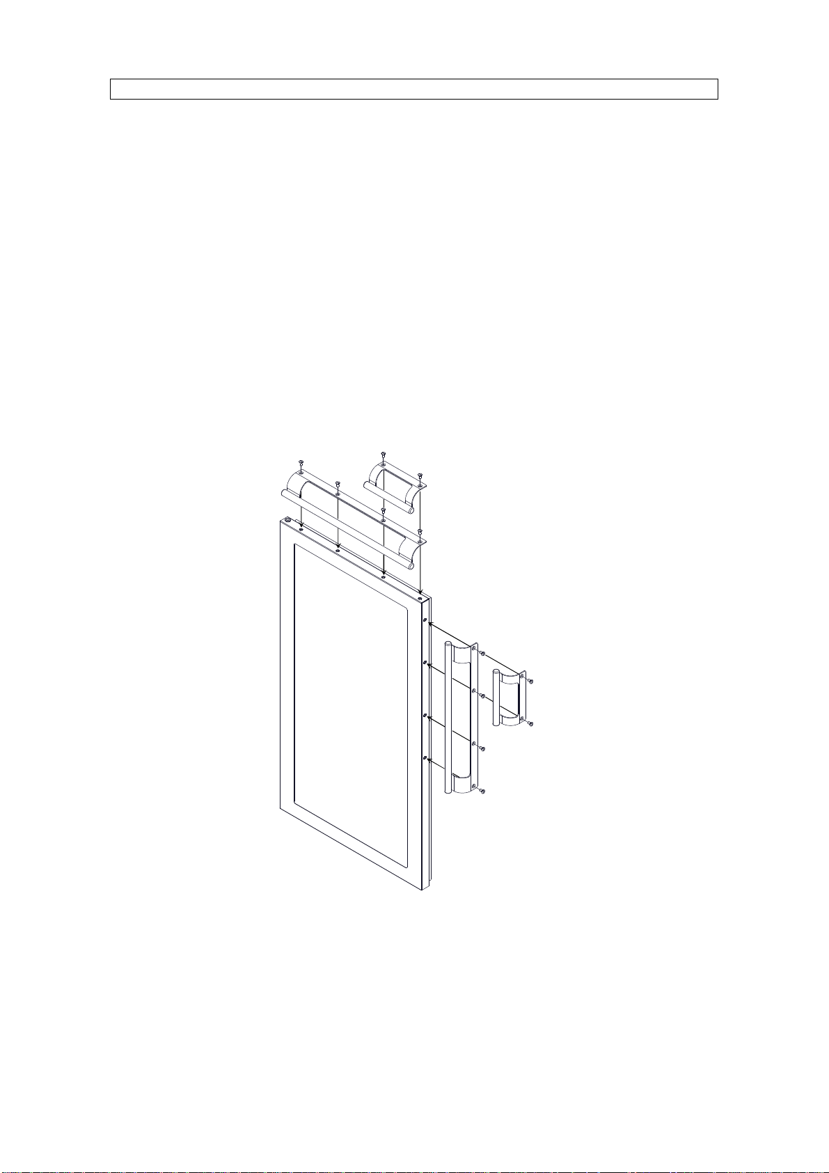
CHANGING OPTION DOOR HANDLES
The option doors have 2 types of handle which are removed and fitted in the
same way. However, the long handle option has 4 screws and the short handle
option has 2 screws.
To change or move a handle:
·Open the front cabinet door(s)
·Using a phillips screw driver, unscrew all the screws that secure the
handle in place, then remove the handle and retain the screws
·Place new / same handle in desired position (see orientations below)
·Fix the handle back to the door with the same / supplied screws
·New / additional handles are available from IMC

VR60
–
GLASS FROSTER
10
ELECTRICITY SUPPLY CONNECTION
Position the unit in the chosen site. The electricity supply connection should be
made to a power outlet socket or isolator mounted on the wall close to the
machine. This socket or isolator must be accessible once the machine is
installed. Before connecting, check that the voltage shown on the rating label is
correct for the electricity supply you have available. If the plug does not fit your
sockets or a longer lead is required, changes must be made by an approved
electrician.
NOTE: The plug is fitted with a 10amp fuse.
The plug fuse cover must be refitted when changing the fuse. In the event of
losing the fuse cover the plug must NOT be used until a replacement fuse cover
has been obtained and fitted or the plug replaced.
WARNING: This machine must be earthed
Should the supply cord become damaged then a replacement must be fitted by
an approved electrician. The IEE Codes of Practice must be observed.
The wires in the mains lead are coloured in accordance with the following code
Green and yellow Earth
Blue Neutral
Brown Live
COMMISSIONING
Before using a bottle cooler for the first time, the interior should be wiped out
with a clean damp cloth.
Allow the machine to stand for 1 hour to allow the refrigerant to settle. Plug in
and switch on at the wall socket. There is no separate switch to turn on the
machine. The compressor will start running less than one minute after the
supply is switched on.
Check that the “ECO”button is not depressed i.e. the blue logo is illuminated.
(See relevant section for the operation of this “ECO”function)
Check that the light is working. If a fluorescent light is fitted, the switch is
located inside the cabinet, on the left hand end of the top inner panel.
Run the unit empty, and check that cold air is being circulated within the
cabinet.
VR60
–
GLASS FROSTER
11
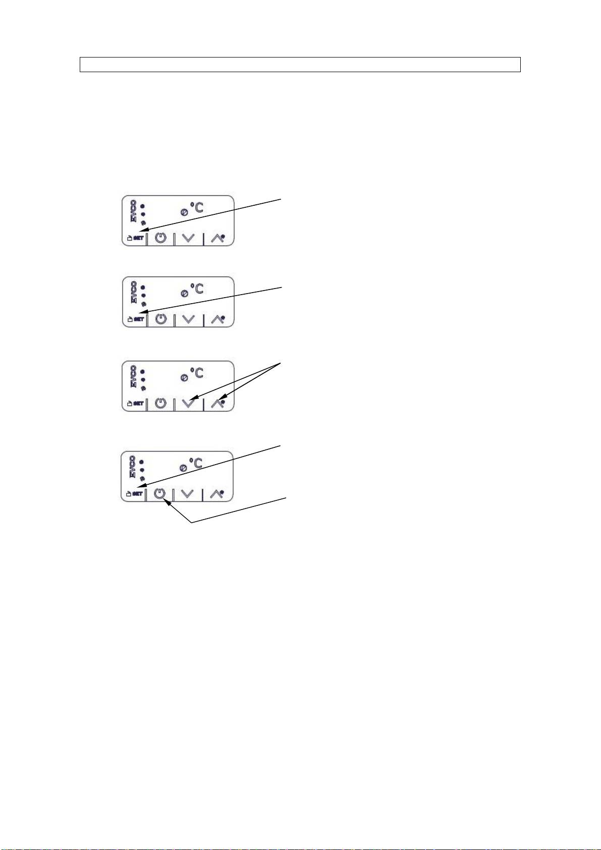
CHANGING THE CONTROLLER SET POINT
The electronic temperature controller is factory set to -10°C and will cycle the air
temperature between -8°C and -12°C. The set point can be adjusted between -
-10°C and -15°C by following the button sequence below:
USING YOUR GLASS FROSTER
This unit is for Frosting Glasses only. Do not load the cabinet with boxed goods
as this prevents air circulation and the goods will not cool down as quickly.
While loading ensure that the interior grilles are not obstructed by the bottles.
Do not place hot or warm goods in the cabinet. Only goods at room
temperature or less should be placed in the unit, otherwise performance will be
affected. It is recommended that the cabinet is stocked after closing at night or
first thing in the morning to allow time for the glasses to cool. Ensure that stock
is rotated by placing new stock at the back of shelves or in one side of the
cabinet to ensure that colder glasses are used first.
Do not leave the doors open when the unit is running as this causes the
evaporator to ice up, preventing the unit from operating efficiently.
Ensure that the front grille is always unobstructed.
1)
Use the UP and DOWN buttons, to scroll to the
desired set point temperature (min
-
15°C, max
-
10°C)
2)
-12
Press SET button to
accept
3)
-10
4)
Press SET button and the current set point
temperature will be displayed
-12
Then press stand-by button to esc.
Display will revert back to current
internal air temperature
-10
Press SET the current SET Point will be displayed, if
Loc is displayed then the controller is locked, to
unlock press and hold the SET button for 3 seconds,
UnL will then be displayed
VR60
–
GLASS FROSTER
12
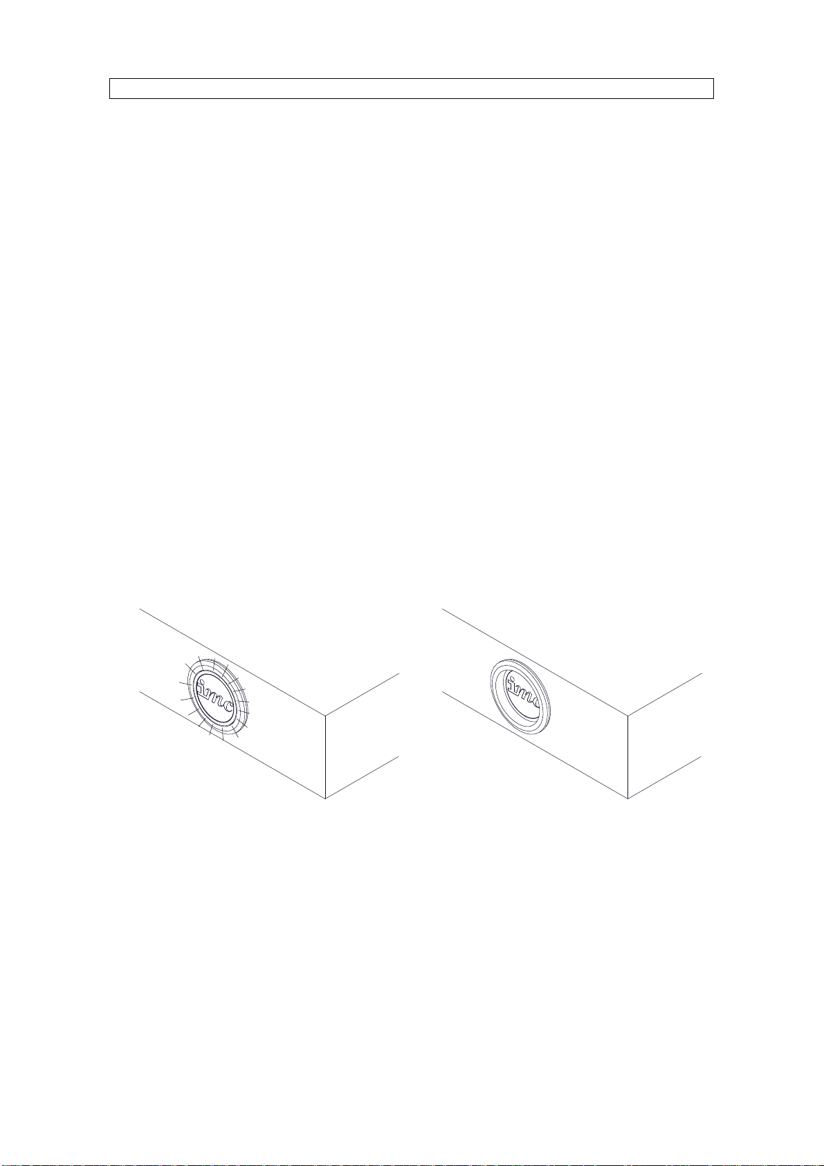
ECO BUTTON FUNCTION
This button (located in the right hand corner of the worktop) provides an energy
saving when depressed i.e. blue logo is not illuminated.
This button switches off the internal light and raises the cabinet’s current “set”
point by 6°C ( e.g. if current set point is -10°C it will be raised to -4°C) while in
the depressed state (e.g. over night or during periods when the bar is closed).
This will provide an energy saving to the customer providing the door(s) is (are)
kept closed during this period. This saving can vary depending on the type and
mix of stock within the cabinet, and also the length of time the cabinet is in this
economy mode.
When the cabinet is placed in economy mode a “green”symbol in the bottom
left hand corner of the controller flashes to indicate it is in ECO mode, and will
stop flashing once the cabinet is returned to standard mode.
To return to standard operation the button must be released i.e. blue logo will
be illuminated, and the internal light will illuminate. The “set”point of the cabinet
will return to its original setting. (cooling the bottles/cans to normal serving
temperature)
Eco mode: Button depressed,
logo & internal light off –(symbol
flashes on controller)
Standard mode: Button released,
logo & internal light illuminated
VR60
–
GLASS FROSTER
13
CLEANING
Clean doors and surfaces as required, occasionally remove all merchandise
and clean interior surfaces with a clean damp cloth.
DO NOT USE CLEANING MATERIALS CONTAINING ABRASIVES OR
BLEACHES.
In the case of heavy soiling use a mild liquid detergent. The unit can be
washed on the inside using bicarbonate of soda to remove stale smells.
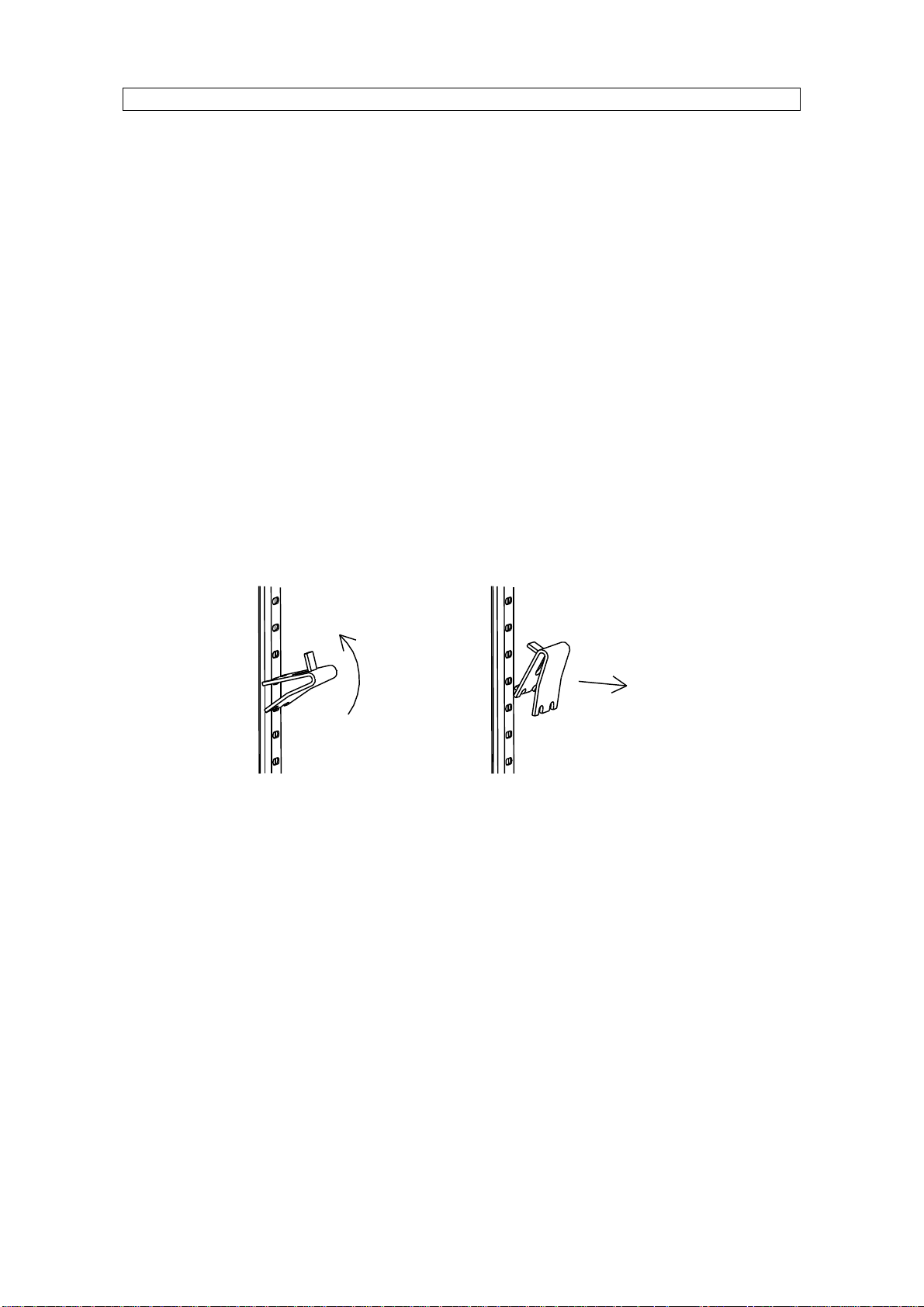
CHANGING SHELF POSITION
The shelves in all VR60 Glass Froster units are fully adjustable. To adjust the
shelves:
·Remove the shelf.
·Unclip the shelf supports as shown below.
·Hook the shelf supports in the required location.
·Ensure all shelf supports are at the same height for a level shelf. The
support strips are numbered to aid positioning.
·Replace the shelf.
Extra shelves are available from IMC.
VR60
–
GLASS FROSTER
14
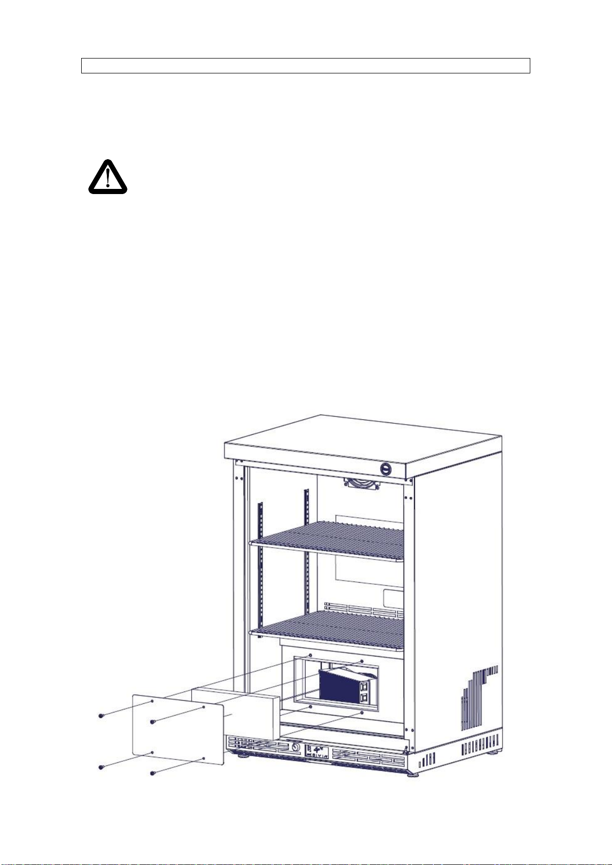
MAINTENANCE
Warning
Never service, repair or troubleshoot a unit unless you are a
professional air conditioning / refrigeration service person. Improper
servicing can lead to serious injury or death from fire, electric shock or
explosion.
Remove the service panel and insulation block inside the cabinet after
switching the unit off from the mains supply. Clean the compressor coil
with a brush and vacuum cleaner. THIS MUST BE DONE every three
months or when dirty (whichever is sooner). Re-fit the insulation and
service panel and secure with the original screws. Once the service panel
has been re-fitted clean the grille at the bottom front of the cabinet. Re-
connect the power supply and check that unit returns to normal operation.
Service / access
panel

VR60
–
GLASS FROSTER
15
Other than regular cleaning the unit requires no maintenance by the end user. It
is recommended that the unit is serviced by an IMC approved engineer at least
once a year.
Details of IMC Service Contracts are available on application.
DO’S AND DON’TS
Do Install on a level surface.
Do Ensure plug is accessible with the unit installed.
Do Regularly clean the condenser and compressor.
Do Rotate stock of glasses.
Don’tSit or stand on the unit worktop.
Don’tLoad with boxed goods.
Don’tLeave the doors open.
Don’tCover the shelves with any protective materials which may obstruct air
circulation through them.
Don’tInstall unit in direct sunlight.
Don’tBlock the air inlet grilles.
Don’tStore food in the unit.
Don’tPlace hot or warm goods in the unit.
Don’tUse the unit outside.

VR60
–
GLASS FROSTER
16
ORDERING SPARE PARTS
In the event that spare parts or accessories need to be ordered, please always
quote the SERIES AND SERIAL NUMBER of the machine. This is to be found
inside the cabinet.
For installations outside the UK please contact your supplier.
For information on IMC spares and service support (if applicable), please call
IMC on +44 (0)1978 661155. Alternatively, contact us via email or fax:
IMC Service Desk Fax: +44 (0)1978 667766
E-mail: service@imco.co.uk
IMC Spares Desk Fax: +44 (0)1978 667759
E-mail: spares@imco.co.uk
END OF LIFE DISPOSAL
At the end of its useful life the unit must be disposed of correctly and safely, to
meet the requirements of EU legislation regarding the recovery of ozone
depleting substances. The unit must be sent to a specialist recovery, recycling
and disposal site that is licensed for the disposal of refrigerated equipment.
Please note that the insulation in the VR60 range does not contain any ozone
depleting substances. The refrigerant used in the VR60 is R452a.
IMC can arrange removal of your redundant Glass Frosters, transfer to safe
storage and disposal.
For more information contact IMC sales department.
MATERIAL CONTENT
The VR60 units may contain a combination of the following materials;
Metals Stainless Steel, Mild Steel (inc. Nickel Plated, Chrome
Plated & Zinc Plated), Aluminium and Copper
Plastics & Rubber PVC, Nylon, Polypropylene, Polycarbonate, Polyester,
Acetate, Neoprene Rubber and Silicone Rubber
Insulation Polystyrene, Polyurethane Foam
Oils & Gases Ester oil, Refrigerant R452a
Other Glass, Magnesium Oxide, electronic components.
VR60
–
GLASS FROSTER
17
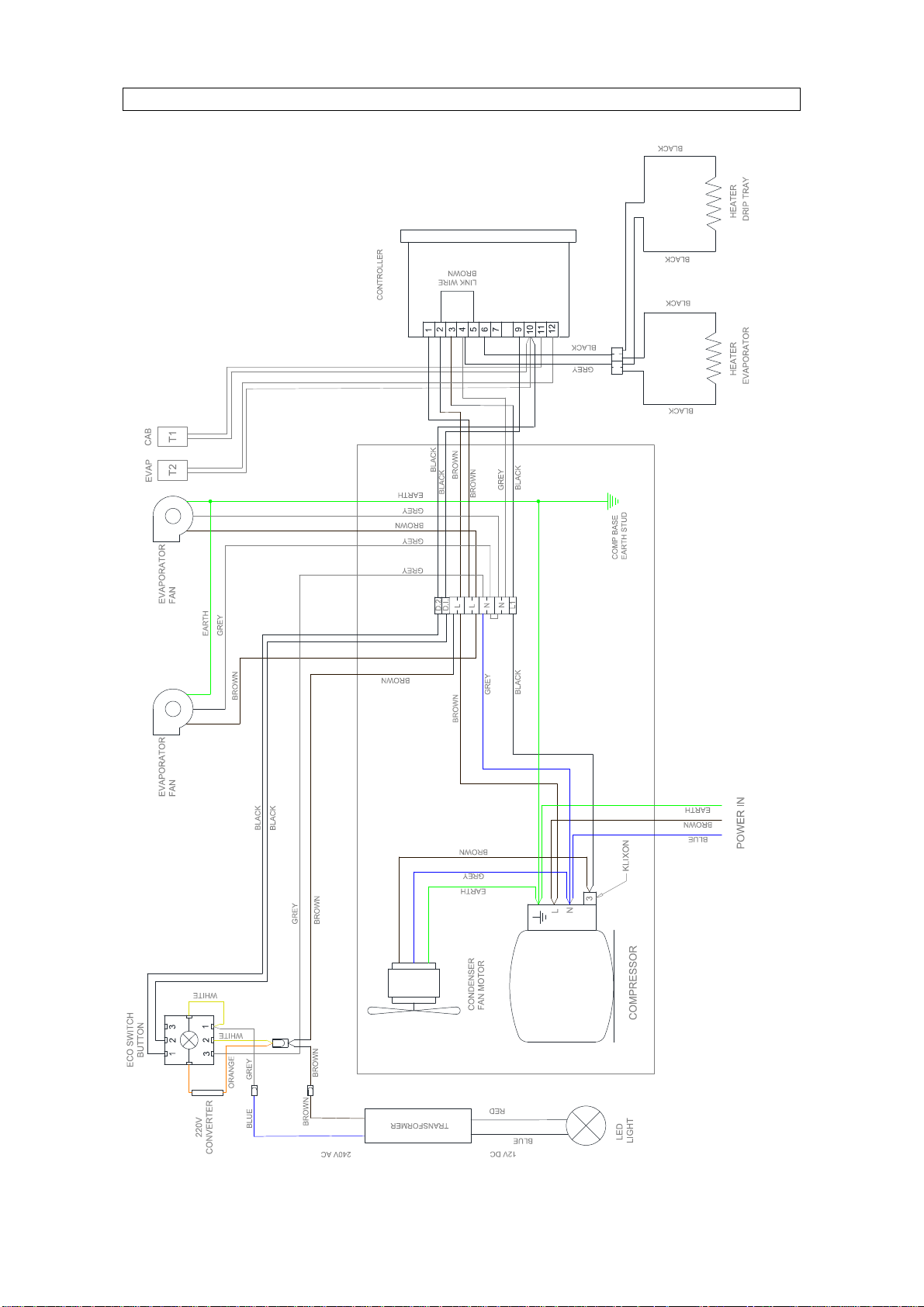
WIRING DIAGRAM

VR60
–
GLASS FROSTER
18
SPARES LIST DRAWING 1
Door Gasket
Electronic
Controller
Door
ECO Button
Shelf
Lock
Shelf Clip
Evaporator
Fan
Pilaster
Strip
Glider
Foot
VR60
–
GLASS FROSTER
19
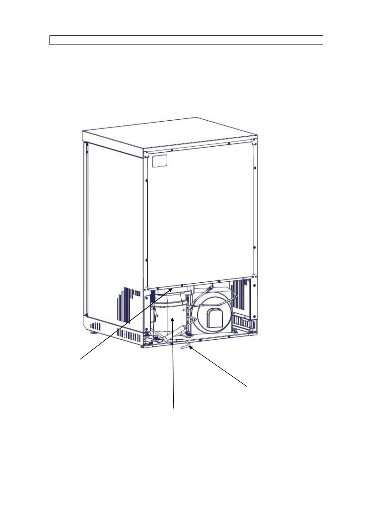
SPARES LIST DRAWING 2
Plastic Drip Tray
Compressor
(Fridge
Pack)
Mains Cable
VR60
–
GLASS FROSTER
20
SPARES LIST
V
R60 Glass Froster
–
Series
4
Part No
D
escription
A11/278 Door Gasket (900)
A11/284 Door Gasket (800)
A12/073 Pilaster Strip
A12/091 Z1 Shelf
A12/082 Wine Shelf
S76/025 Perforated Shelf VR60
A12/094 Shelf Clip (4 per shelf)
A19/027 Glider Foot
A21/011 Lock, clip & keys
E76/221 Access panel
G30/562 Electronic Controller
G42/020 Plastic Drip Tray
G60/348 M1 Mains Cable
S49/066
S49/071 Refrigeration Pack (900)
Refrigeration Pack (800)
J09/049 Condenser/fan motor assembly
J09/026 Evaporator
J09/007 Service Drier
X08/057 (2mtr) Capillary V60
G96/049 Evaporator Fan
S76/018 Door Handle (Short)
S76/023 Door Handle (Long)
S76/250 LED Assembly (white)
S76/253 LED Assembly (red)
S76/256 LED Assembly (blue)
S76/259 LED Assembly (green)
This manual suits for next models
2
Table of contents
Other IMC Freezer manuals


