IMER MASTER 6010 DXL15 YN DE User manual
INSTRUCTION FOR USE EN
MANUEL D’UTILISATION FR
MANUEL DE USUARIO ES
MANUALE D’USO IT
MANUAL DE UTILIZARE RO
MASTER 6010 DXL15 YN DE
TRISTAR 6510 DXL15 YN DE
MIXTE 5000 DXL15 YN DE
ARC 180 DXL15 YN DE
MU_02GE_MAST_TRI_MIXTE_ARC_YN_IMER
2
(a)
(b)
(a)
START
OFF
ON
START
OFF
ON
1
1
6
5
7
8
2
3
4
4
1
1
2
1
2
2

3
START
OFF
ON
12
13
13
14
9
10
11
1
2
4
Thank you for purchasing an IMER generator. This manual covers operation and maintenance of
the IMER generators. All information in this publication is based on the latest production information
available at the time of approval for printing. Pay special attention to statements preceded by the
following words:
Indicates an impending dangerous situation. If this one is not prevented, it can
cause death or severe injuries for the user.
Indicates a strong possibility of severe personal injury, loss of life and
equipment damage if instructions are not followed.
NOTE Gives helpful information.
If a problem should arise, or if you have any questions about the generator, consult an authorized dealer
or service shop.
The generator is designed to give safe and dependable service if operated according to
instructions. Do not operate the generator before you have read and understood the instructions.
Failure to do so could result in death, personal injury or equipment damage.
SUMMARY
Page
1. SYMBOLS AND MEANINGS . . . . . . . . . . . . . . . . . . . . . . . . . . . . . . . . . . . . .5
2. SAFETY PRECAUTIONS. . . . . . . . . . . . . . . . . . . . . . . . . . . . . . . . . . . . . . .6
3. SPECIFICATIONS . . . . . . . . . . . . . . . . . . . . . . . . . . . . . . . . . . . . . . . . . .8
4. PRE-OPERATION CHECK . . . . . . . . . . . . . . . . . . . . . . . . . . . . . . . . . . . . . .9
5. OPERATING PROCEDURES . . . . . . . . . . . . . . . . . . . . . . . . . . . . . . . . . . .11
6. STOPPING THE GENERATOR . . . . . . . . . . . . . . . . . . . . . . . . . . . . . . . . . .13
7. OIL SENSOR . . . . . . . . . . . . . . . . . . . . . . . . . . . . . . . . . . . . . . . . . . . . 13
8. WATTAGE INFORMATION . . . . . . . . . . . . . . . . . . . . . . . . . . . . . . . . . . . . . 13
9. MAINTENANCE SCHEDULE. . . . . . . . . . . . . . . . . . . . . . . . . . . . . . . . . . . . 15
10. ‘‘HOW TO DO’’ MAINTENANCE . . . . . . . . . . . . . . . . . . . . . . . . . . . . . . . . .15
11. PREPARATION FOR STORAGE . . . . . . . . . . . . . . . . . . . . . . . . . . . . . . . . . 16
12. TROUBLESHOOTING . . . . . . . . . . . . . . . . . . . . . . . . . . . . . . . . . . . . . .17
13. ELECTRICAL DIAGRAM . . . . . . . . . . . . . . . . . . . . . . . . . . . . . . . . . . . . .18
14. DECLARATION OF CONFORMITY. . . . . . . . . . . . . . . . . . . . . . . . . . . . . . . . 19
5
EN
FR
ES
IT
RO
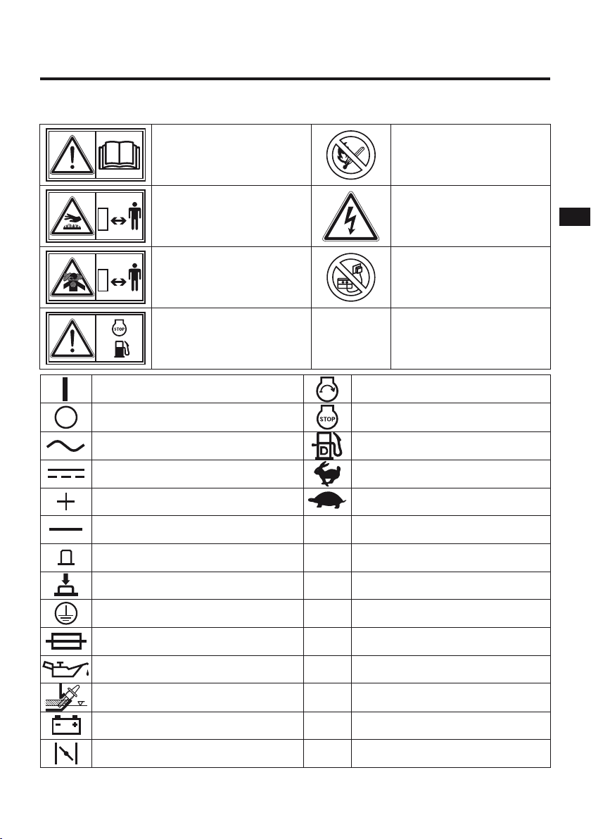
1. SYMBOLS AND MEANINGS
In accordance with the ISO standard, the specified symbols as shown in the following table are used
for the products and this instruction manual.
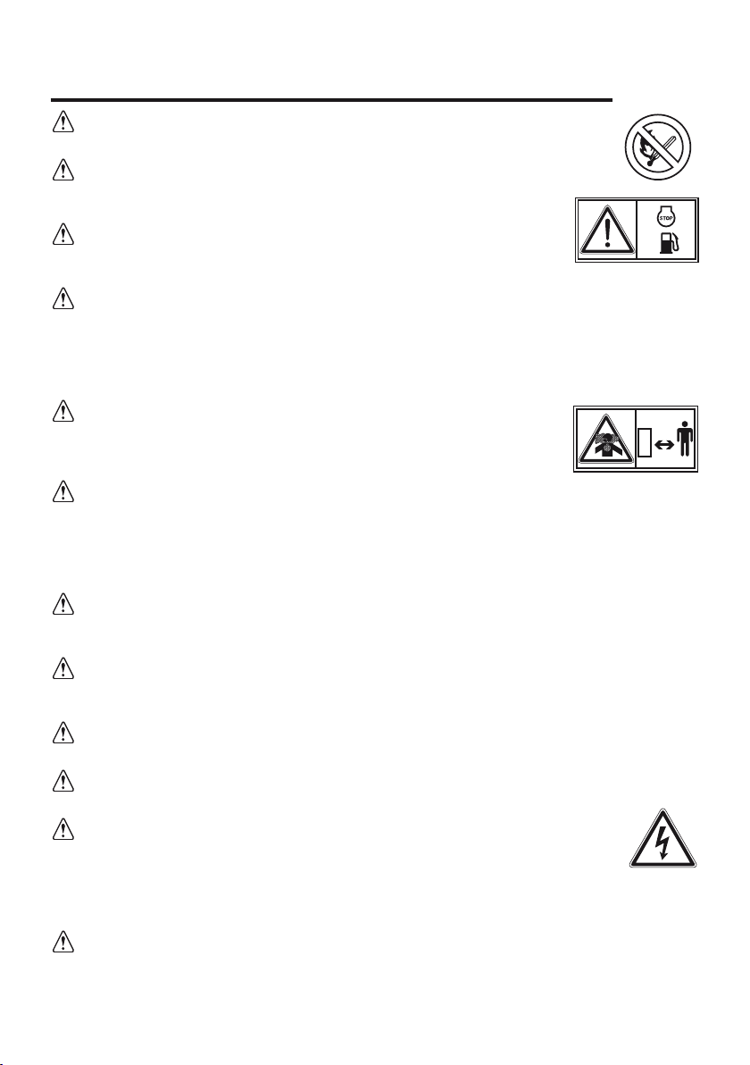
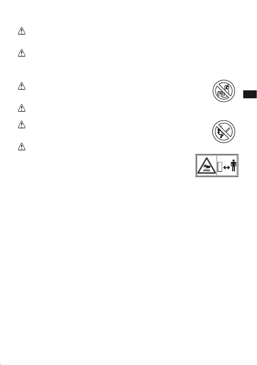
Read the operator’s
instruction manual. Fire, naked flame and
smoking prohibited.
Stay clear of the hot surface. Caution, risk of electric shock.
Exhaust gas is poisonous.
Do not operate in an
unventilated room.
Do not connect the generator
to the commercial power
lines.
Stop the engine before
refueling.
ON (Switch Engine) Engine start (Electric start)
OFF (Switch Engine) Engine stop (Electric start)
Alternating current Fuel
Direct current Fast
Plus : positive polarity Slow
Minus : negative polarity Pr Rated power (kW)
STOP-position of a bistable push control ƒr Rated frequency (Hz)
ON-position of a bistable push control H max Maximum site altitude above
sea-level (m)
Protective earth (ground) COP Continuous power (kW)
Fuse U rRated voltage (V)
Engine oil Tmax Maximum ambient temperature (°C)
Add oil COS ϕRated power factor
Battery charging condition Ir Rated current (A)
Choke (cold starting aid) mMass (kg)
6
2. SAFETY PRECAUTIONS
Do not operate the generator near gasoline or gaseous fuel because of the potential
danger of explosion or fire.
Do not fill the fuel tank with fuel while the engine is running. Do not smoke or use a
naked flame near the fuel tank. Be careful not to spill fuel during refueling. If fuel
is spilt, wipe it off and let dry before starting the engine.
Do not place inflammable near the generator. Be careful not to place fuel,
matches, gunpowder, oily cloths, straw, trash, or any other in flammables near
the generator.
Do not operate the generator inside a room, cave, tunnel, or other insufficiently ventilated area.
Always operate it in a well-ventilated area, otherwise the engine may become overheated, and the
poisonous carbon monoxide gas contained in the exhaust gases will endanger human lives. Keep the
generator at least 1 meter (3 feet) away from any structure or building during use. If the generator must
be used indoors, the area must be well-ventilated and extreme caution must be taken regarding the
discharge of exhaust gases. Failure to follow the correct procedures can be fatal.
Do not enclose the generator nor cover it with a box. The generator has a
built-in forced air cooling system, and may become overheated if it is enclosed. If
generator has been covered to protect it from the weather during non use, be sure
to remove it and keep it well away from the area during generator use.
Operate the generator on a level surface. It is not necessary to prepare a special foundation for
the generator. However, the generator will vibrate on an irregular surface, so choose a level place
without surface irregularities. If the generator is tilted or moved during operation, fuel may spill and/ or
the generator may tip over, causing a hazardous situation. Proper lubrication cannot be expected if the
generator is operated on a steep incline or slope. In such a case, piston seizure may occur even if the
oil level is above the minimum level.
Pay attention to the wiring or extension cords from the generator to the connected device. If the
wire is under the generator or in contact with a vibrating part, it may break and possibly cause a fire,
generator burnout, or electric shock hazard. Replace damaged or worn cords immediately.
Do not operate in rain, in wet or damp conditions, or with wet hands. The operator may suffer
severe electric shock if the generator is wet due to rain or snow.
If the generator is wet, wipe and dry it before starting. Do not pour water directly over the generator,
never wash it with water.
Be extremely careful that all necessary electrical grounding procedures are followed during each
and every use. Failure to do so can be fatal.
Do not contact the generator to a commercial power line. Connection to a commercial
power line may short circuit the generator and ruin it or cause electric shock hazard.
Use the transfer switch for connecting to domestic circuit. In the special case where the
generator will be connected as stand by to the commercial network, the installation must be carried
out by a qualified electrician taking into account the technical specifications of the generator and the
commercial network.
No smoking while handling the battery. The battery emits flammable hydrogen gas, which can
explode if exposed to electric arcing or a naked flame. Keep the area well-ventilated and keep naked
flames/sparks away when handling the battery.
7
EN
FR
ES
IT
RO
Engine becomes extremely hot during and for some time after operation. Keep combustible
materials well away from generator area. Be very careful not to touch any parts of the hot engine
especially the muffler area or serious burns may result.
Keep children and all bystanders at a safe distance from work areas.It is absolutely essential that
you know the safe and proper use of the power tool or appliance that you intend to use. All operators
must read, understand and follow the tool/appliance owners manual. Tool and appliance applications
and limitations must be understood. Follow all directions given on labels and warnings. Keep all
instruction manuals and literature in a safe place for future reference.
Use only «Homologated» extension cords according to CEI 245-4. When a tool
or appliance is used outdoors, use only extension cords marked «For Outdoor Use».
Extension cords, when not in use should be stored in a dry and well ventilated area.
Always switch off generator’s circuit breaker and disconnect tools or appliances when not in use,
before servicing, adjusting, or installing accessories and attachments.
Electrolyte used in the battery contains sulphuric acid: always protect your eyes, skin
and clothes. In case of contact, rinse using plenty of water and call immediately a doctor,
especially in case of contact with eyes.
The battery produces hygrogen. Hydrogen is a very explosive gas. Never smoke
and never expose the battery to a naked flame or sparks, especially when it is
being charged. Charge the battery in a well-ventilated room. Always check the
polarity of the battery.
8
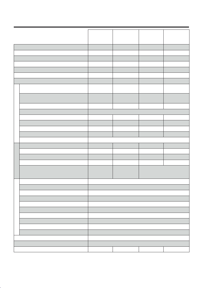
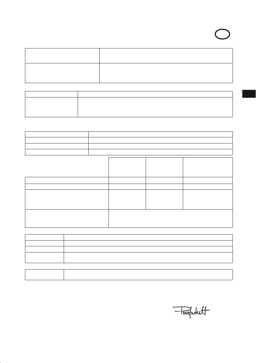
3. SPECIFICATIONS
MASTER
6010 DXL15
YN DE
TRISTAR
6510 DXL15
YN DE
MIXTE
5000 DXL15
YN DE
ARC
180 DXL15
YN DE
Maximum power LTP (400V 3-phase) -5.2 kW -4.7 kW
Maximum rating 22.6 A 9.4 A 22.4 A 8.5 A
Max. power. cosϕ=0,8 (400V 3-phase) -6,5 kVA -5.9 kVA
Maximum power LTP (230V 1-phase) 5.2 kW 3.0 kW 5.15 kW 3.5 kW
Max. power. cosϕ=0,8 (230V 1-phase) 6.5 kVA -6.5 kVA -
Continuous power (COP) 4.5 kW 4.5 kW 4.5 kW 4.1 kW
electrode maximum diameter - - Ø 4 Ø 4
ALTERNATOR
Nominal voltage 230V
1-phase. 400V 3-phase
230V 1-phase. 230V
1-phase. 400V 3-phase
230V 1-phase
Alternator type (2 poles) Ringless
Brushless with ring and
brushes Ringless
Brushless with ring and
brushes
Voltage regulator Condenser Compound Condenser Compound
Frequency 50 Hz
1-phase socket 230V - 10/16A Schuko 1121
1-phase socket 230V - 16A CEE ----
1-phase socket 230V - 32A CEE 1 - - -
3-phase socket 400V 3P+N+T 16A -1-1
Protection Sockets protected by a circuit breaker
WELDING
Rating range - - 60A - 180 A 40 A - 220 A
Priming alternative voltage - - 50 - 62.5 V 73 V
Minimum welding voltage - - 22.4 V 21.6 V
Operating factor (35%) - - 180 A 220 A
Equipments - - Rating rheostat
+ power selecting button
+ welding terminal
ENGINE
Engine Model YANMAR - L100
Engine Type Diesel 1-cylinder
Cooling System Air cooled
Maximum Output 9.3 HP at 3600 rpm
Piston Displacement 435 cm3
Fuel GNR or diesel oil
Fuel Tank Capacity 15 Liters
Autonomy at ¾ Load 9 h 45
Starting system Electrical
Electronic Oil Sensor Serial
Frame Full steel frame
Dimensions LxWxH (mm) 875 x 535 x 635
Dry Weight 95,5 kg 120 kg 109 kg 115 kg
9
EN
FR
ES
IT
RO
4. PRE-OPERATION CHECK
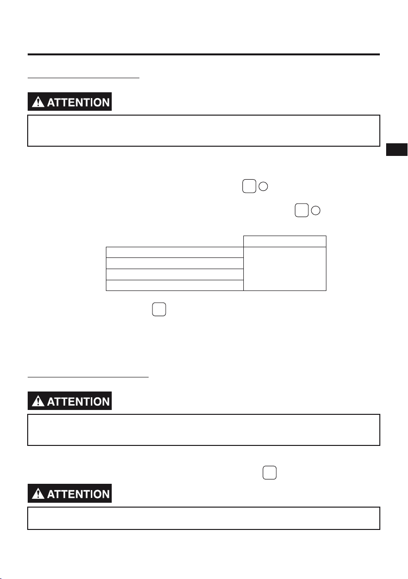
4.1. CHECK ENGINE OIL
Do not remove the fuel tank cap while the engine is running. Do not refuel while smoking or near
naked flame or other such potential fire hazards. Otherwise fire accident may occur.
Before checking or refilling oil, be sure generator is located on stable and level surface with engine
stopped.
•
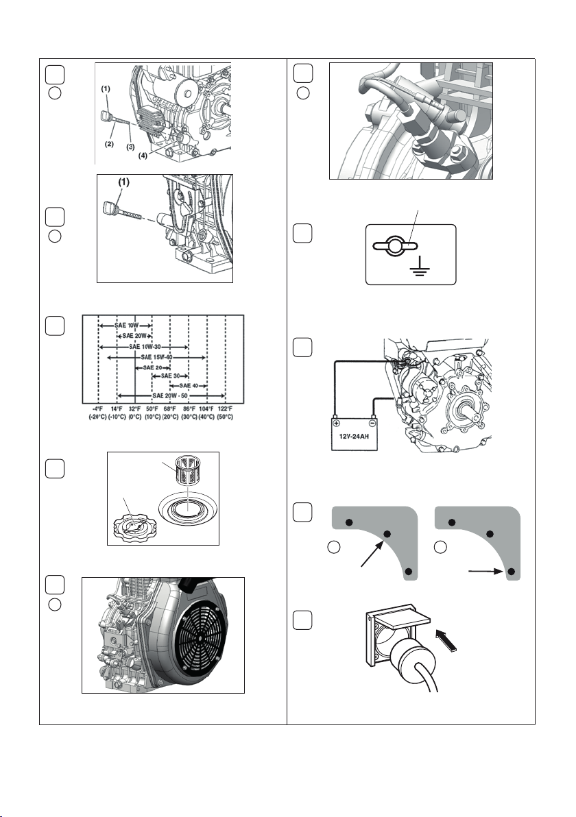
Remove oil filler cap (1) and clean it using a clean cloth. Fig. 11.
•
Recap the filling plug, making 1/2 turn. If the oil level is less than the minimum level (3), top up using
proper oil (please refer to the table) up the the maximum level mark (2). Fig. 12.
•
Change oil if contaminated (See ‘‘How-To’’ Maintenance).
Oil Capacity Upper level
MASTER 6010 DXL15 YN DE
1.6 L
TRISTAR 6510 DXL15 YN DE
MIXTE 5000 DXL15 YN DE
ARC 180 DXL15 YN DE
RECOMMENDED ENGINE OIL Fig. 2:
Use class SE (API classification) oil or a higher grade oil according to the table below.
SAE 10W-30 is recommended for general, all temperature use. If single viscosity oil is used, select the
appropriate viscosity for the average temperature in your area.
4.2. CHECK ENGINE FUEL
Do not remove the fuel tank cap while the engine is running. Do not refuel while smoking or near
naked flame or other such potential fire hazards. Otherwise fire accident may occur.
Check fuel level at fuel level gauge. If fuel level is low, refill with GNR or diesel oil. Be sure to use the
fuel filter screen on the fuel filter neck. Fuel tank capacity: 15 L. Fig. 3
The diesel oil filter must be full. If it is not, perform an air bleeding.
10
4.3. PERFORMING AN AIR BLEEDING OF THE FUEL LINE Fig. 4
Following the first start or when you run out of fuel.
If there is air into the diesel oil filter or the feeding hose, remove the feeding hose from the injection
pump and perform a bleeding.
•
Make sure you review each warning in order to prevent fire hazard.
•
Do not refill tank while engine is running or hot.
•
Be careful not to admit dust, dirt, water or other foreign objects into fuel.
•
Wipe off spilt fuel thoroughly before starting engine.
•
Keep naked flames away.
4.4. CHECKING COMPONENT PARTS
Check following items before starting engine:
•
Fuel leakage from fuel hose, etc;
•
Bolts and nuts for looseness;
•
Components for damage or breakage;
•
Generator not resting on or against any adjacent wiring;
•
Control generator environment.
4.5. GROUNDING THE GENERATOR Fig. 5
•
Before using the generator, the grounding lug on the panel must be connected to the earth.
•
To ground the generator to the earth, connect the grounding lug of the generator to the grounding spike
driven into the earth or to the conductor which has been already grounded to the earth.
•
If such grounding conductor or grounding electrode is unavailable, connect the grounding lug of the
generator to the grounding terminal of the using electric tool or appliance.
•
Make sure you review each warning in order to prevent fire hazard.
•
Keep area clear of in flammables or other hazardous materials.
•
Keep generator at least 3 feet (1 meter) away from buildings or other structures.
•
Only operate generator in a dry, well ventilated area.
•
Keep exhaust pipe clear of foreign objects.
•
Keep generator away from naked flame. No smoking!
•
Keep generator on a stable and level surface.
•
Do not block generator air vents with paper or other material.
4.6. SETTING UP THE BATTERY Fig. 6
The battery is delivered dry but loaded. You have to fill it with acid before using. In order to preserve its
lifespan and its performance, always perform a slow charging.
1. Just before filling the battery, take out the plastic cap and connect the hose to the mechanical out
connection.
2. Remove the tank cap and fill fully with electrolyte until the maximum level written on the battery.
3. Let the battery rest for a while (roughly 1/2 HRS) before running by a load. If the electrolyte level
dropped, fill again until the maximum level.
4. If necessary, reload the battery. The loading can be made with unscrewing the filling caps.
5. Remove the plugs and clean the electrolyte that fell down on the battery. The battery is ready for use.

11
EN
FR
ES
IT
RO
ABOUT THE BATTERY CABLES
1. Fix the positive (+) wire connected to the electrical starter to the positive terminal of the battery.
2. Fix the negative (-) wire connected to the housing of the engine to the negative terminal of the
battery.
5. OPERATING PROCEDURES
• Check the oil level before each operations as outlined on page 9. Never change the accelerator
position which is set at the factory.
• Prior to operating the generator, please check that air is completely bled from diesel oil feeding pipes.
5.1. STARTING THE ENGINE
•
Turn the engine switch to the position « I » (ON). Fig. 71.
•Hold the key on the START position and release the key when the engine starts. Fig. 72.
If the engine does start, do not hold the key on the Start position for more than 5 seconds, for each try..
If a power inverter or a remote control is used, the unit contactor must be placed on the OFF position.
•
Perform a no-load préheating of the engine during several minutes.
5.2. USING ELECTRIC POWER
AC APPLICATION
This generator is thoroughly tested and adjusted in the factory. If the generator does not produce the
specified voltage, consult your nearest IMER dealer or service shop.
Turn off the switch(es) of the electrical appliance(s) before connecting to the generator. Fig. 8
Insert the plug(s) of the electrical appliance(s) into the receptacle.
Be sure to ground the generator if the connected electrical device is grounded.
Failure to ground unit could lead to electrical shock.
•
Check the amperage of the receptacles, and be sure not to take a current exceeding the specified
amperage.
•
Be sure that the total wattage of all appliances does not exceed the rated output of the generator.
Fig. 9
Do not put foreign objects into the plug receptacle.
12
NOTE
When the circuit breaker or no-fuse breaker turns off during operation, the generator is overloaded or
the appliance is defective. Stop the generator immediately, check the appliance and/or generator for
overloading or detect and have repaired as necessary by IMER dealer or service shop.
5.3. ‘MIXTE’ WELDING TABLE Fig. 10
1Grounding socket. 4« Generator / Welding » mode switch button.
2Low range welding plug. 5Rated value switch button.
3High range welding plug.
[GENERATOR MODE]
To use this operating mode, the switch (4) must be set on the (GEN) position and the rated value switch
button (5) must be set to the maximum value. So all alternator single-phase power plugs can be used.
[WELDING MODE]
To use this operating mode, the switch (4) must be set on the (WELD) position. Connect the wire of
the ground jaw to the plug (1). Connect the ground jaw to the part to weld. Connect the wire of the
electrode-holder to the plug (2) or (3) according to the range of power required. Select the range of
power using the switch (5) (the blue marking is for the low range and the red marking is for the high
range).
During the welding, alternator plugs are live but the voltage is both low and not stable. Therefore,
for safety reasons, we recommand to unplug all equipments.
The alternator is designed to produce a maximal power over a limited period. Over this period, a
cooling time is required (see indication 6 on the plate)Therefore, when working using high power
triggers the thermal protection, please wait several minutes before resetting this thermal protection.
5.4. ‘ARC’ WELDING TABLE Fig. 11
1Grounding socket. 3Range switch button.
2Rated value switch button. 4Welding plug.
[GENERATOR MODE]
To use this operating mode, the switch (3) must be set on the (GEN) position.

13
EN
FR
ES
IT
RO
[WELDING MODE]
Connect the wire of the ground jaw to the plug (1). Connect the ground jaw to the part to weld.Connect
the wire of the electrode-holder to the plug (4). Select the range of power using the switch (3). Select
the welding power using the switch (2) (the black scale is for the low range, the blue scale is for the
medium range and the red scale is for the high range).
During the welding, alternator plugs are live but the voltage is both low and not stable. Therefore,
for safety reasons, we recommand to unplug all equipments.
The alternator is designed to produce a maximal power over a limited period. Over this period, a
cooling time is required (see indication 6 on the plate)Therefore, when working using high power
triggers the thermal protection, please wait several minutes before resetting this thermal protection.
6. STOPPING THE GENERATOR
1. Turn off the power switch of the electric equipment and unplug the cord from the receptacle of
the generator.
2. Allow the engine about 3 minutes to cool down at no-load before stopping.
3. Turn the key to the OFF position (STOP). Fig. 12
4.
When storing the generator, always turn the key to the OFF position. Otherwise, in case the
generator is not used over a long period, the battery may discharge.
7. OIL SENSOR
1. The oil sensor detects the fall in oil level in the crankcase and automatically stops the engine when
the oil level falls below a predetermined level.
2. When engine has stopped automatically, switch off generator’s no-fuse breaker, and check the oil
level. Refill engine oil to the upper level as instructed on page 8 and restart the engine.
3. If the engine does not start by usual, consult your nearest IMER dealer or service shop.
8.WATTAGE INFORMATION
Some appliances need a «surge» of energy when starting. This means that the amount of electrical
power needed to start the appliance may exceed the amount needed to maintain its use. Electrical
appliances and tools normally come with a label indicating voltage, cycles/Hz, amperage (amps) and
electrical power needed to run the appliance or tool. Check with your nearest dealer or service center
with questions regarding power surge of certain appliances or power tools.
•
Electrical loads such as incandescent lamps and hot plates require the same wattage to start as is

14
needed to maintain use.
•
Loads such as fluorescent lamps require 1.2 to 2 times the indicated wattage during start-up.
•
Loads for mercury lamps require 2 to 3 times the indicated wattage during start-up.
•
Electrical motors require a large starting current. Power requirements depend on the type of motor and
its use. Once enough «surge» is attained to start the motor, the appliance will require only 30% to 50%
of the wattage to continue running.
•
Most electrical tools require 1.2 to 3 times their wattage for running under load during use. For
example, a 5,000 W generator can power a 1,800 to 4,000 W electrical tool.
•
Loads such as submersible pumps and air compressors require a very large force to start. They need
3 to 5 times the normal running wattage in order to start. For example, a 5,000 W generator would only
be able to drive a 1,000 to 1,700 W pump.
NOTE
The following wattage chart is general guide only. Refer to your specific appliance for correct wattage.
To determine the total wattage required to run a particular electrical appliance or tool, multiply the
voltage figure of the appliance/tool by the amperage (amps) figure of the same appliance / tool. The
voltage and amperage (amps) information can be found on a name plate which is normally attached to
electrical appliances and tools.
MASTER
6010 DXL15
YN DE
TRISTAR
6510 DXL15
YN DE
MIXTE
5000 DXL15
YN DE
ARC
180 DXL15
YN DE
Bulb - Heating 4,500 W 1,500 W / phase 4,500 W 1,360 W / phase
Halogen - Neon 2,275 W 750 W / phase 2,250 W 680 W / phase
Hand Tools Without Load 2,800 W 930 W / phase 2,800 W 850 W / phase
Compressor 1,500 W 500 W / phase 1,500 W 450 W / phase
Electric Motor without Load 3,000 W 1,000 W / phase 3,000 W 900 W / phase
VOLTAGE DROP IN ELECTRIC EXTENSION CORDS
When a long electric extension cord is used to connect an appliance or tool to the generator, a certain
amount of voltage drop or loss occurs in the extension cord which reduces the effective voltage
available for the appliance or tool.
The chart below has been prepared to illustrate the approximate voltage loss when an extension cord
of 300 feet (approx. 100 meters) is used to connect an appliance or tool to the generator.
Section
No.
A.W.G.
Allowable
Current
Nb. / Ø
Resistance
Amperage (A)
mm2No. A No./mm /100m 1 A 3 A 5 A 8 A 10 A 12 A 15 A
0.75 18 7 30/0.18 2.477 2.5V 8V 12V - - - -
Chute de tension
1.27 16 12 30/0.18 1.486 1.5V 5V 7.5V 12V 15V 18V -
2.0 14 17 37/0.26 0.952 1V 3V 5V 8V 10V 12V 15V
3.5 12 to 10 23 45/0.32 0.517 - 1.5V 2.5V 4V 5V 6.5V 7.5V
3.5 10 to 8 35 70/0.32 0.332 - 1V 2V 2.5V 3.5V 4V 5V

15
EN
FR
ES
IT
RO
9. MAINTENANCE SCHEDULE
Daily
(8 h) •
Check all components according to ‘’PRE-OPERATING CHECKS’’.
•
Check and refill gasoline and engine oil.
Every
50 h •
Wash air cleaner foam element more often if used in dirty or dusty environments.
•
Check the condition of the paper element. Do not wash the paper element.
Every
200 h •
Replace air cleaner element.
•
Change oil more often if used in dusty or dirty environnement.
Every
300 h •
Check and adjust valve clearance.
Every
500 h •
Remove carbon from cylinder head and the top of the cylinder.
•
Clean and adjust carburetor.
•
Replace engine mount rubber.
Every
1000 h
(24 months)
•
Inspect control panel parts.
•
Check rotor and stator.
•
Overhaul engine.
•
Change fuel lines.
NOTE
•
Maintenance operations require trained and qualified personel.
•
The maintenance schedule is given as a guide. Under severe conditions, the frequency of maintenance
must be increased.
•
Initial oil change should be performed after first twenty (20) hours of use. Thereafter change oil every
100 hours. Before changing the oil, check for a suitable way to dispose of the old oil. Do not pour
it down sewage drains, onto garden soil or into open streams. Your local zoning or environmental
regulations will give you more detailed instructions on proper disposal.
10. ‘‘HOW-TO’’ MAINTENANCE
10.1. ENGINE OIL CHANGE
Change engine oil every 200 hours. (For new engine, change oil after 50 hours).
•
Make sure the engine is stable.
•
Start the engine and let it heat.
•
Stop the engine.
•
Place a container to collect used oil.
•
Remove the draining plug located on the lower part of the cylindr carter (2). Fig. 13 1
•
Remove the filling plug (1) to make the draining easier. Fig. 13 1
•
Once all oil is drained, fit the draining plug (19.6 - 23.5 Nm). Fig. 13 1
•
Inspect the oil filter.
•
Untighten screw (1) of the oil filter. Fig. 13 2
•
Take the oil filter (3) out of its housing (2). Fig. 13 2
•
Clean the oil filter using an adapted product or replace it if it is damaged.
•
Oil the O-ring.
•
Fit the oil filter and tighten the screw.
•
Fill the engine using new oil.
•
Operate the engine during 5 minutes and look out for leaks.
16
•
Stop the engine and wait 10 minutes.
•
Control the oil level.
Use fresh and high quality lubricating oil to the specified level as directed on page 9. If contaminated or
deteriorated oil is used or the quantity of the engine oil is not sufficient, the engine damage will result
and its lifespan will be greatly shortened.
10.2. MAINTENANCE OF THE AIR FILTER
A dirty filter element can cause a difficult starting, a drop of power, a bad running of the engine and a
very early wear of the engine. Always make sure the element of the air filter is clean.
URETHANE FOAM DOUBLE TYPE ELEMENT Fig. 14
Urethane foam element (1): wash and clean the urethane foam using a detergent. Dry following
cleaning. Wash the urethane foam element every 50 operating hours.
Paper element (2): clean by tapping on it to remove dirt and dust. Also you may wash the element using
water. Dry it afterwards. Never use oil. Clean the paper element every 50 operating hours and replace
every 200 hours.
Wash air cleaner foam element more often if used in dirty or dusty environments.
URETHANE FOAM CLEANING : Remove the element, wash and clean the urethane foam in
kerosene. Saturate in a mixture of 3 parts kerosene and 1 part engine oil, and then squeeze
to remove excess oil and put it back to the air filter.
10.3. CHECKING THE VOLTAGE OF THE BATTERY
•
Check, from time to time, from the outside, the level of electrolyte.
•
Regularly add distilled water. The level of acid must be over the lower level. if it goes under this line,
add some more distilled water up the upper level. Never use electrolyte to top up.
•
Always maintain good charging conditions for the battery. Otherwise, charge it.
• Regularly check proper tightness of all screws and nuts of terminals, because vibrations tend to unscrew them.
DO NOT START ANY FIRE.
11. PREPARATION FOR STORAGE
The following procedures should be followed prior to storage of your generator for periods of 6 months
or longer:
•
Drain fuel from fuel tank carefully by disconnecting the fuel line. Gasoline left in the fuel tank will
eventually deteriorate making engine-starting difficult.
•
Change engine oil.
•
Check for loose bolts and screws, tighten them if necessary.
•
Clean generator thoroughly with oiled cloth. Spray with preservative if available.
•
Stock the generator in a well ventilated and low humidity area.
NEVER USE WATER TO CLEAN YOUR GENERATOR!

17
EN
FR
ES
IT
RO
12. TROUBLESHOOTING
When generator engine fails to start after several attempts, or if no electricity is available at the
output socket, check the following chart. If your generator still fails to start or to generate electricity,
contact your nearest IMER dealer shop for further information or corrective procedures.
12.1. WHEN ENGINE FAILS TO START:
Check if choke lever is in its proper position. Set the choke lever to ‘‘CLOSE’’ position.
Check if fuel cock is open. Set the choke lever to ‘‘CLOSE’’ position.
Check to make sure generator is not connected
to an appliance. If connected, turn off the power switch on the
connected appliance and unplug.
Check the charge level of the battery. Must be over12V. Charge the battery.
Check the proper connection of the solenoid valve
power cables and of the oil sensor. Connect cables again, if necessary.
12.2. WHEN NO ELECTRICITY IS GENERATED AT RECEPTACLE:
Check to make sure no-fuse breaker is in
the ‘‘l’’ (ON) position.
After making sure that the total wattage of the electrical
appliance is within permissible limits and there are no
defects in the appliance, turn the no-fuse breaker to the
‘‘l’’ (ON) position. If breakers continue to actuate, consult
your nearest servicing dealer.
Check AC terminals for loose connection. Secure connection if necessary.
Check to see if engine starting was
attempted with appliances already
connected to generator.
Turn off switch on the appliance, and disconnect cable
from receptacle. Reconnect after generator has been
started properly.
18
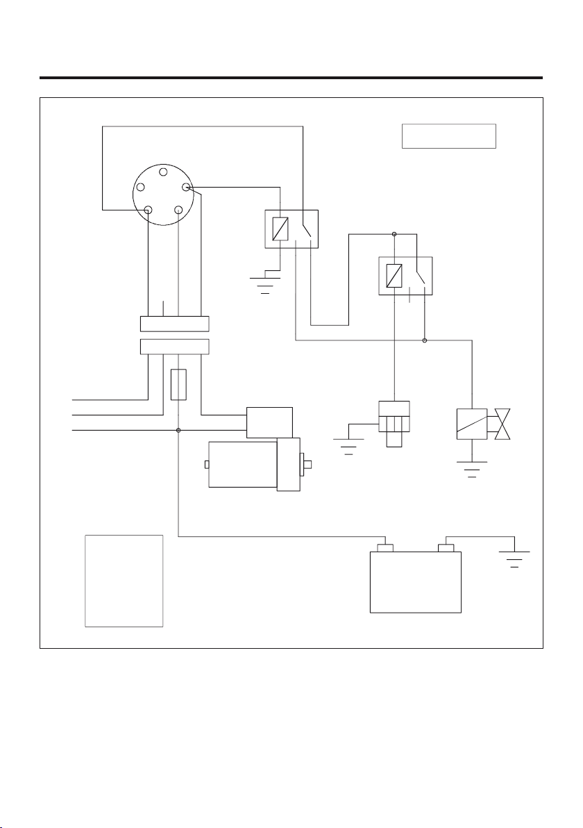
13. ELECTRICAL DIAGRAM
Version : 01.0
B+
dem
STARTER
+M
-M ST
B
IG
CONTACTOR
+-
12V -
BATTERY
OIL SENSOR
SOLENOID
86 30
85 87a
87
86 30
85 87a
87
to regulator
CONNECTOR
24 Ah
j 1.25
bl 1.25
v 1.25
r 1.25
61n61r
v 1.5
bl 1.5
r 1.5
v 1.5
r 1.5
r : red
bl : white
v : green
j : yellow
n : black
changeover
relay
12V - 25A
changeover relay
12V - 25A
19
EN
FR
ES
IT
RO
EG-KONFORMITÄTSERKLÄRUNG
Hersteller WORMS ENTREPRISES
Parc Gustave Eiffel, 1 Bd. de Strasbourg Bussy Saint Georges
77607 Marne la Vallée Cedex 3 France
Name und Anschrift der Person, die für tech-
nische Dokumentation verantwortlich ist
Paul HASKETT, Produktionsleiter
WORMS ENTREPRISES
Parc Gustave Eiffel, 1 Bd. de Strasbourg Bussy Saint Georges
77607 Marne la Vallée Cedex 3 France
Beschreibung des Geräts
Produkt Stromerzeuger
Handelsbezeichnung Master 4010 DXL15 Master 6010 DXL15 Master 6010 DXL15 YN DE
Tristar 6510 DXL15 Tristar 6510 DXL15 YN DE
Mixte 5000 DXL15 Mixte 5000 DXL15 YN DE
Arc 180 + DXL15 Arc 180 + DXL15 YN DE
Der Unterzeichnende, Paul HASKETT, den Hersteller repräsentierend, erklärt hiermit, daß das Produkt mit den
Forderungen der folgenden EG- Amtsblattsverfügungen übereinstimmt :
2006/42/CE Maschinenrichtlinie
2006/95/CE Niederspannungsrichtlinie
2004/108/CE Elektromagnetische Verträglichkeit
2005/88/CE et 2000/14/CE Umweltbelastende Geräuschemissionen von zur Verwendung im Freien vorgesehe-
nen Geräten und Maschinen
Master 4010 DXL15
Master 6010 DXL15
Tristar 6510 DXL15
Mixte 5000 DXL15
Arc 180 + DXL15
Master 6010 DXL15 YN DE
Tristar 6510 DXL15 YN DE
Mixte 5000 DXL15 YN DE
Arc 180 + DXL15 YN DE
Gemessener Schalldruckpegel (Lwa) 109 dBA 109 dBA 102 dBA
Garantierter Schalldruckpegel (Lwa) 110 dBA 110 dBA 103 dBA
Steuerpflichtige Elektrische Leistung
(3000 min.-1) 2,6 kW
5,15 kW
5,10 kW
5,15 kW
4,70 kW
5,20 kW
5,20 kW
5,15 kW
4,70 kW
Bewertungsverfahren zur Feststellung der
Übereinstim-mung und offizieller Amt für die
Richtlinie 2000/14/EG
Annex VI – n°071:
LNE, 1 rue Gaston Boissier 75724 Paris France
Verweis auf harmonisierte Normen
EN 12601 Stromerzeugungsaggregate mit Hubkolben – Verbrennungsmotoren – Sicherheit
EN 60204-1 Sicherheit von Maschinen – Allegemeine Anforderungen
ISO8528 Groupes électrogènes à courant alternatif entrainés par moteurs alternatifs à combustion
interne.
EN ISO 3744 : 1995
Bestimmung der Schalleistungspegel von Geräuschquellen aus Schalldruckmessungen
– Hüllflächenverfahren der Genauigkeitsklasse 2 für ein im wesentlichen freies Schallfeld
über einer reflektierenden Ebene.
Andere angewandte nationale Normen oder Spezifikationen
CISPR 12
Fahrzeuge, Boote und von Verbrennungsmotoren angetriebene Geräte –
Funkstöreigenschaften – Grenzwerte und Messverfahren zum Schutz von Empfängern mit
Ausnahme derer, die in den Fahrzeugen, Booten, Geräten selbst oder in benachbarten
Fahrzeugen, Booten, Geräten installiert sind.
“EC” DECLARATION OF CONFORMITY
Manufacturer WORMS ENTREPRISES
Parc Gustave Eiffel, 1 Bd. de Strasbourg Bussy Saint Georges 77607
Marne la Vallée Cedex 3 France
Name and address of the person who
keeps the technical documentation
Paul HASKETT, Production manager
WORMS ENTREPRISES
Parc Gustave Eiffel, 1 Bd. de Strasbourg Bussy Saint Georges 77607
Marne la Vallée Cedex 3 France
Description of the equipment
Product Generating set
Trade name Master 4010 DXL15 Master 6010 DXL15 Master 6010 DXL15 YN DE
Tristar 6510 DXL15 Tristar 6510 DXL15 YN DE
Mixte 5000 DXL15 Mixte 5000 DXL15 YN DE
Arc 180 + DXL15 Arc 180 + DXL15 YN DE
The undersigned, Paul HASKETT, representing the manufacturer, herewith declares that the product is in conformity with
the provisions of the following EC-directives :
2006/42/EC Machinery directive
2006/95/EC Low voltage equipment
2004/108/EC Electromagnetic compatibility
2005/88/EC y 2000/14/EC Noise emission for the environment by equipment for use outdoors
Master 4010 DXL15
Master 6010 DXL15
Tristar 6510 DXL15
Mixte 5000 DXL15
Arc 180 + DXL15
Master 6010 DXL15 YN DE
Tristar 6510 DXL15 YN DE
Mixte 5000 DXL15 YN DE
Arc 180 + DXL15 YN DE
Measured sound power level (Lwa) 109 dBA 109 dBA 102 dBA
Guaranteed sound power level (Lwa) 110 dBA 110 dBA 103 dBA
Rated electric power at 3000 rpm 2,6 kW
5,15 kW
5,10 kW
5,15 kW
4,70 kW
5,20 kW
5,20 kW
5,15 kW
4,70 kW
Conformity assessment procedure and notified
body according the 2000/14/EC directive
Annex VI – n°071:
LNE, 1 rue Gaston Boissier 75724 Paris France
Reference to harmonized standards
EN 12601 Reciprocating internal combustion engines driven generating sets – Safety
EN 60204-1 Safety of machinery – Electrical equipment of machines
ISO8528 Groupos electrogenos de coriente alternativo propulsados por motores de combustion interna.
EN ISO 3744: 1995 Determination of sound power levels of noise sources using sound pressure - Engineering
method in an essentially free field over a reflecting plane
Other national standards or specifications used
CISPR 12 Vehicle, motorboats and spark-ignited engine-driven-devices-Radio disturbance
characteristics, limits and methods of measurement
Ort Bussy-St-Georges Paul Haskett
Datum : August 2013 Produktionsleiter
Done at Bussy-St-Georges Paul Haskett
Date : August 2013 Production manager
DCE_02GE_MIXTE_EX_ARC_EX
EN
DE
20
Nous vous remercions d’avoir fait l’acquisition d’un groupe électrogène IMER. Ce manuel traite de
l’utilisation et de l’entretien des groupes électrogènes IMER. Toutes les informations indiquées dans
ce document sont établies à partir des données les plus récentes du produit, connues au moment
de l’impression.
Vous devez accorder une attention particulière aux indications précédées des termes suivants :
Indique une situation dangereuse imminente. Si elle n’est pas évitée peut
entraîner la mort ou de graves blessures.
Cela indique qu’il existe de grands risques de lésions corporelles graves, de
mort et d’endommagement de l’appareil, au cas où les instructions ne sont pas
observées.
REMARQUE Fournit une information utile.
Au cas où survient un problème, ou pour des questions concernant le groupe électrogène, prendre
contact avec le fournisseur agréé ou un service après vente IMER.
Un groupe électrogène est conçu pour fournir des performances sûres et fiables, s’il est utilisé
conformément aux instructions. Ne mettre en marche le groupe électrogène qu’après avoir lu et
bien compris les instructions. Autrement, les conséquences peuvent être des lésions corporelles,
la mort ou l’endommagement de l’appareil.
SOMMAIRE
Page
1. SYMBOLES ET LEUR SIGNIFICATION . . . . . . . . . . . . . . . . . . . . . . . . . . . . . . 21
2. MESURES DE SÉCURITÉ . . . . . . . . . . . . . . . . . . . . . . . . . . . . . . . . . . . . . 22
3. DONNÉES TECHNIQUES . . . . . . . . . . . . . . . . . . . . . . . . . . . . . . . . . . . . . 24
4. CONTRÔLES AVANT LA MISE EN MARCHE . . . . . . . . . . . . . . . . . . . . . . . . . . . 25
5. PROCÉDURES DE MISE EN MARCHE . . . . . . . . . . . . . . . . . . . . . . . . . . . . . . 27
6. ARRÊT DU GROUPE ÉLECTROGÈNE . . . . . . . . . . . . . . . . . . . . . . . . . . . . . .29
7. SÉCURITÉ MANQUE D’HUILE. . . . . . . . . . . . . . . . . . . . . . . . . . . . . . . . . . . 30
8. INFORMATIONS SUR LA PUISSANCE . . . . . . . . . . . . . . . . . . . . . . . . . . . . . .30
9. CALENDRIER D’ENTRETIEN . . . . . . . . . . . . . . . . . . . . . . . . . . . . . . . . . . .31
10. MODALITÉS D’ENTRETIEN . . . . . . . . . . . . . . . . . . . . . . . . . . . . . . . . . . .32
11. PRÉPARATION AU STOCKAGE . . . . . . . . . . . . . . . . . . . . . . . . . . . . . . . . .33
12. SOLUTIONS DES PROBLÈMES . . . . . . . . . . . . . . . . . . . . . . . . . . . . . . . . . 33
13. SCHÉMA ÉLECTRIQUE . . . . . . . . . . . . . . . . . . . . . . . . . . . . . . . . . . . . .34
14. DÉCLARATION DE CONFORMITÉ. . . . . . . . . . . . . . . . . . . . . . . . . . . . . . . . 35
This manual suits for next models
3
Table of contents
Languages:
Popular Portable Generator manuals by other brands


Winco
Winco DP14000VE-03/A Installation and operator's manual

NSM
NSM PMG-LT Use and maintenance manual

APE
APE 700VM Operation & maintenance manual

Krüger Technology
Krüger Technology KGVG4001 instruction manual

Pulsar
Pulsar HD6580B Operator's manual

Predator
Predator 59206 Owner's manual & safety instructions


