IMG BRASIL BIMG METVISA FTE.150 User manual

1

2
CONGRATULATIONS,
You have just purchased a IMG-BRASIL equipment, product of the highest quality, safety and
efficiency.
Founded in 1989, IMG-BRASIL is a respected company as one of the best and most complete
companies in the field of gastronomy equipment manufacturing.
Constant innovation and improvement of its products, using top-of-the-line raw materials,
ensure superior products consumed in Brazil and in more than 25 countries worldwide.
THE RELIABILITY AND CERTAINTY OF A GOOD PRODUCT ARE IN THE NAME
IMPORTANT:
PRODUCTFORPROFESSIONALUSE.DONOTUSE BEFOREREADINGTHEMANUAL
CAREFULLY.
INCASEOFQUESTIONS,PLEASECONTACT US:
IMG-BRASIL Indústria de Máquinas para Gastronomia Ltda.
CNPJ 11.193.347/0001-14 - CREA 131726-3
Rod. Antônio Heil –KM 23 Nº 5825 –Bairro: Limoeiro –CEP 88352-502 - Brusque –SC –
Brasil Phone/fax. +55 47 3251-5555 - Website: www.metvisa.com.br

3
INDEX
1. Safety Information ............................................................................................................ 4
1.1 General Warnings ........................................................................................................................4
1.2 Mechanical Safety........................................................................................................................5
1.3 Electrical Safety............................................................................................................................5
2. Technical Features ........................................................................................................... 6
2.1 Main Components........................................................................................................................6
2.2 Technical Data.............................................................................................................................7
2.3 Supply and Disposal of Equipment Packagin ...............................................................................8
3. Instalação.......................................................................................................................... 8
3.1 Equipment Layout ........................................................................................................................8
3.2 Hydraulic Installation ..................................................................................................................11
3.3 Electrical Connection..................................................................................................................13
3.4 Safety Procedures and User Instruction.....................................................................................15
4. Use of Equipment ........................................................................................................... 15
4.1 Utility.........................................................................................................................................15
4.2 Commands................................................................................................................................16
4.3 Operating Procedures ...............................................................................................................18
5. Cleaning and Maintenance............................................................................................. 24
5.1 Cleaning Procedures and Products Used..................................................................................24
5.2 Maintenance and Behavior in Case of Breakdowns...................................................................25
5.3 Prolonged Interruption in Use of Equipment..............................................................................26
6. Analysis and Troubleshooting ...................................................................................... 26
6.1 Problems, possible causes and solutions..................................................................................26
7. Appliance Life and Components................................................................................... 27
8. ANNEXES ........................................................................................................................ 26
Electrical Schematic FTE.150 - Voltage 220 V - Single Phase Connection ......................................26
Electrical Schematic FTE.150 - Voltage 220 V - Three Phase Connection.......................................26
Electrical Schematic FTE.300 - Voltage 220 V - Three Phase Connection.......................................27
Electrical Schematic FTE.150 - Voltage 380 V - Three Phase Connection.......................................28
Electrical Schematic FTE.300 - Voltage 380 V - Three Phase Connection.......................................29
Explosion Design .............................................................................................................................30
Replacement parts...........................................................................................................................34
ATTENTION!
The characteristics, pictures and figures presented in this manual should be considered for
information. IMG BRASIL reserves the right to make such modifications as may be deemed
necessary without prior notice.

4
1. Safety Information
1.1 General Warnings
•Cautions / precautions must be observed when installing, using, maintaining and discontinuing use of
this equipment;
•Before carrying out any operation (assembly, use (use), maintenance and reuse after prolonged use
of the equipment), read the manual carefully;
•The equipment must be used by trained personnel familiar with the use and safety regulations
described in this manual;
•This appliance is not intended for use by persons (including children) with reduced physical, sensory
or mental capacities, or people with lack of experience and knowledge, unless they have received
instructions regarding the use of the device or are under the supervision of a person responsible for
their safety.
•It is recommended that children be supervised to ensure that they are not playing with the equipment;
•In case of alternation of the personnel that will work with the equipment, the new operator must be
educated about the standards and the operation of the same one;
•The operator must use the Adequate PPE (equipment for individual safety). For example: suitable
gloves protecting the hands from burns by heating the oven;
•The operator must always be aware of situations that can cause a risk of accidents and avoid them.
Do not operate the equipment in damp locations or with wet clothing and shoes. Wear proper footwear,
this will prevent electric shocks and even death;
•After being held to read and answered all the questions, this manual must be stored carefully in place
of easy access, known by all the people who will operate the equipment and pmade available for the
people who carry out maintenance, to any queries. When in doubt, consult the manual. Do not
operate the equipment in any way with doubts;
•In the installation, it is essential to make this manual available to the professionals who will do the
same;
•Before starting cleaning and any maintenance, it is essentialto disconnect the equipment from the mains;
•Periodically check the condition of the cables and electrical parts;
ATTENTION!
Do not perform repairs on your own. Refer servicing to qualified service personnel. Use only
original parts in your equipment.

5
1.2 Mechanical Safety
•Before operating the equipment, make sure that the gas installation is free of leaks, if the pressure of
the hydraulic system is within the permitted levels (see pressure information in item 3.2 Hydraulic
Installation) and if the door is locked until the handle stroke limit.
•Insert only specific products into the oven for the intended use and never place hands or inflammable
products in or near the oven.
•When cleaning the equipment, take extreme care. Unplug the machine from the electrical outlet, and
then wait for the oven to cool completely. Never put your hands or products for cleaning in the heated
oven. For further information on cleaning the equipment, follow the instructions in item 5 of this
manual.
The equipment described in this manual complies with the mechanical risk regulation. Safety
is obtained with:
1. Structure fixed, preventing inappropriate access to internal parts, such as rock wool and
water pipe;
2. Door with safety system that automatically turns off the fan and the heating of the oven when it
is open. Because it is tempered glass and has lighting, the door allows you to visualize the
foods being baked without having to open it;
3. Stand with the appropriate height for the use of the equipment, following requirements for good
ergonomics.
To view the parts described above, refer to the image in item 2.1 (Main Components - pg. 7)
of this manual.
ATTENTION!
Whenever any item regarding the safety of the equipment (such as cleaning or
maintenance) is removed, reset it and confirm that it is performing its function correctly.
1.3 Electrical Safety
•Periodically check the condition of the cables and electrical parts;
•If the power cord is damaged, it must be replaced with a new one. The exchange must be made by
the manufacturer, authorized agent or a qualified person in order to avoid risk;
•Do not use a water jet as this may cause electric shock. To clean your equipment, follow the
instructions in item 5 of this manual;
•Do not operate the equipment in damp locations or wet clothing and shoes. Wear proper footwear,
this will prevent electric shocks and even death;
6
•Lay the equipment on a firm, dry, level surface;
•Never carry out any maintenance, adjustment or disassembly of the equipment connected to it. For
such procedures, make sure that it is turned off by removing the plug from the electrical outlet;
•Do not use extension cords or adapters with several other devices connected to them. This may cause
a fire or an overload;
•Grounding on this equipment is mandatory;
•The equipment must be connected to an exclusive thermoelectric circuit breaker;
•The door has a safety system that prevents fan operation and heating if it is open;
The removal or tampering of the safety system can cause serious accidents.
Components used for safety against electrical hazards have been selected in accordance
with applicable standards. Given the perfect insulation of all the electrical parts and the excellent
resistor of all the materials used, this unit is able to carry out the works to which they are proposed.
ATTENTION!
Whenever any item regarding the safety of the equipment (such as cleaning or
maintenance) is removed, reset it and confirm that it is performing its function correctly.
2. Technical Features
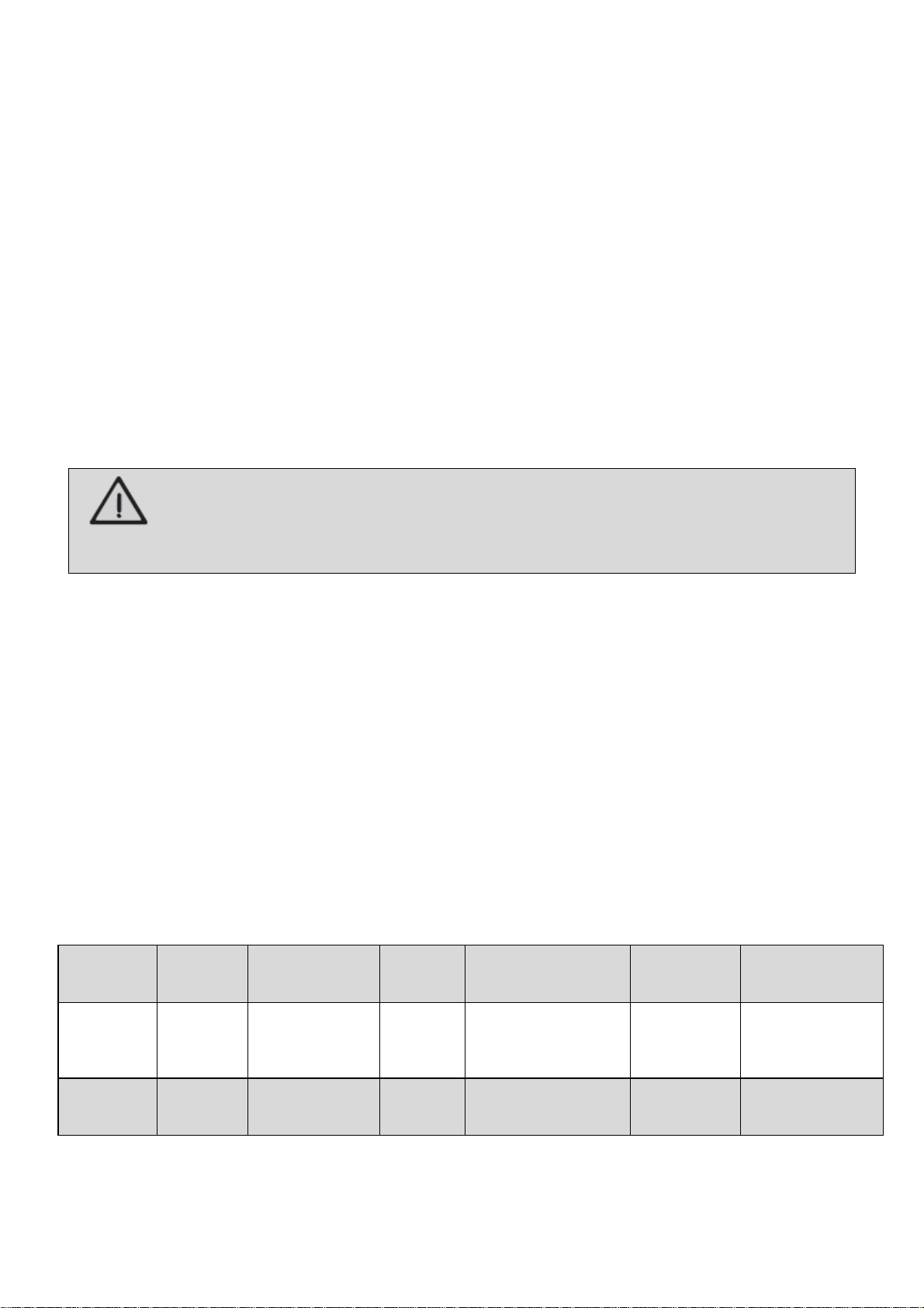
2.1 Main Components
For the equipment described in this manual, safety in use, cleaning, maintenance and
maximum hygiene are guaranteed by the design and special design of all parts and also by using
stainless steel and other materials suitable for contact with the food.
The equipment was built with the following characteristics:
Model
Structure
Interior
Oven
(Chamber)
Support
Door
Garrison
(Door
Seal)
Stand
FTE.150
FTE.300
Carbon
steel with
epoxy paint
Carbonsteelwith
hightemperature
paint
Stainless
steel
Stainless steel
structure,
Tempered glass
Halogen lamp
Silicone
Carbon
steel with
epoxy paint
FTE.150T
FTE.300T
Stainless
steel
Stainless
steel
Stainless
steel
Stainless steel
structure, Tempered
glass Halogen lamp
Silicone
Carbon
steel with
epoxy paint
The following are the main components of the equipment:
7
2.2 Technical Data
Model
Electrical
Cable
Section
Voltage
(V)
Rated
Current
(A)
Energy
Consumption
(kW/h)
Standard Measures
for Operation
Length.xHt.xWidth
(mm) *
Net
Weight
(approx.)
(kg)
Capacity
(bread)
**
Roasting
pans
(unit)
Dimension
Roasting
pans (mm)
FTE150220M60
10 mm²
220 - MF
41
9
1840x1750x2000
155.0
150
05
580x700
FTE150220T60
6 mm²
220 - TF
24
9
FTE150380T60
4 mm²
380 - TF
14
9
FTE150220M50
10 mm²
220 - MF
41
9
FTE150220T50
6 mm²
220 - TF
24
9
FTE150380T50
4 mm²
380 - TF
14
9
FTE150T220M60
10 mm²
220 - MF
41
9
1840x1750x2000
162.0
150
05
580x700
FTE150T220T60
6 mm²
220 - TF
24
9
FTE150T380T60
4 mm²
380 - TF
14
9
FTE150T220M50
10 mm²
220 - MF
41
9
FTE150T220T50
6 mm²
220 - TF
24
9
FTE150T380T50
4 mm²
380 - TF
14
9
FTE300220T60
10 mm²
220 - TF
48
18
1840x1800x2100
245.0
300
10
580x700
FTE300380T60
6 mm²
380 - TF
28
18
FTE300220T50
10 mm²
220 - TF
48
18
FTE300380T50
6 mm²
380 - TF
28
18
FTE300T220T60
10 mm²
220 - TF
48
18
1840x1800x2100
244.5
300
10
580x700
FTE300T380T60
6 mm²
380 - TF
28
18
FTE300T220T50
10 mm²
220 - TF
48
18
FTE300T380T50
6 mm²
380 - TF
28
18
* Measures for operation considered with the oven door open.
** Considering French type breads in the standard size of 50 gr.
Note: For exploded design
with spare parts list, see the
attachments.

8
ATTENTION!
Features like: model, serial number and voltage of the equipment are provided on the label (figure
below). Before installation, check that the power supply voltage of the appliance corresponds to that
of the mains.
2.3 Supply and Disposal of Equipment Packagin
The equipment is packed with wood or cardboard to ensure its perfect integrity during
transport and is accompanied by the following documents:
•Instruction Manual for Installation, Use, Maintenance and Safety;
•Warranty Term (for Brazilian market).
IMPORTANT
The packaging components (cardboard, wood, foam, strips, etc.) are products that can be
assimilated to municipal solid waste and can be disposed of without difficulty. If the equipment is
installed in countries with different standards, dispose of the packaging in accordance with current
regulations. Dispose of the product correctly to help protect the environment. For more information
on recycling, contact your local authorities, waste disposal service or theshop where you purchased
the product.
3. Instalação
3.1 Equipment Layout
In the installation, it is essential to make this manual available to the professionals who will do
the same.
To facilitate transportation, the FTG model oven.150 is packed with the disassembled stand. The
fastening of the pieces of the stand and the top stand must be done with the washers, bolts and nuts
supplied with the equipment.
The stand has 02 side frame units, 02 crossbars, 02 tread supports (optional items), 02 fixed
casters and 02 rotating wheels plus a kit with screws, washers and nuts for fixing the parts. Use
appropriate tools to secure all items.

9
Follow the guidelines below to assemble the stand:

10
With the stand mounted, position the top rack of the oven (FTG.150) on top of the stand,
noting that the swivel casters are positioned in the front of the oven. Mount with washers, bolts and
nuts. Make sure all bolts are tight.
To ensure correct operation and safety, the equipment should be positioned in a sufficiently
wide area, with a well-leveled, dry and stable floor, away from sources of heat and humidity and
where there is no heavy traffic. Install your equipment leaving a free area at the front and a distance of
at least 50 cm around it. The area should have sufficient space for inspection, maintenance,
cleaning and use.

11
It is recommended to install a hood or extractor above the oven to collect the vapors,
avoiding that they spread in the environment.
IMPORTANT
To install the hood follow the manufacturer's instructions as this item does not accompany the
equipment.
ATTENTION!
The installation and the place where the appliance is to be disposed of must comply with the
rules of risk prevention and safety at work (Regulatory standard NR-12 for Brazil or according
to the regulation in force in your country).
Do not install near flammable materials or products.
The manufacturer shall not be liable for any direct or indirect damages caused by non-
compliance with these standards and other instructions presented in this manual.
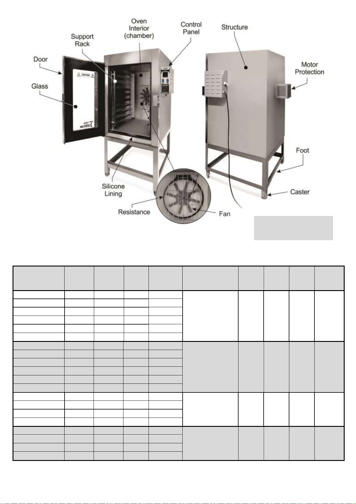
3.2 Hydraulic Installation
To activate the steam function of the oven, it is necessary to install the equipment near a fixed
point of cold water.
12
The equipment is supplied with a solenoid water valve for hose coupling or for fitting a 3/8
"water supply hose (hose and pipes not supplied with the equipment) located on the back of the
control panel housing.
The hose that will be used to connect to the water supply must comply with IEC 61770.
When installing the hose, ensure that the pressure reducing ring (attached to the equipment) is
properly sealed to prevent leakage. Tighten the connection manually. Do not use tools.
The water supply pressure must be at least 20 kPa (3 mA) and at most 78 kPa (8 mA).
ATTENTION!
It is recommended that the water be connected directly from the water box so as not to generate
a high pressure or that it has variation, as in the public network. Very high water boxes should
also be avoided.
It is also recommended to install a filter to eliminate water impurities, avoiding the calcification
and internal corrosion of the equipment.
Install a water log on the grid to allow water to be closed when necessary.
ATTENTION!
In case of use of removable hoses to feed the equipment, it is recommended that new hoses
should always be used and comply with IEC 61770. In case of hose changes, dispose of old
hoses and always replace with new hoses.
The power supply hose does not come with the machine.
13
In case the excess steam turns into water inside the oven (chamber), it may be drained
through the water outlet pipe located between the bottom of the chamber and the oven burners. It is
advisable to install a point to drain this water, avoiding that the floor is wet and slippery and can
cause accidents.
3.3 Electrical Connection
The equipment is supplied with a plug-in power cable to be connected directly to the mains
or to an industrial type plug suitable for each type of current (refer to the current for each model of
equipment in the table of item 2.2 Technical Data).
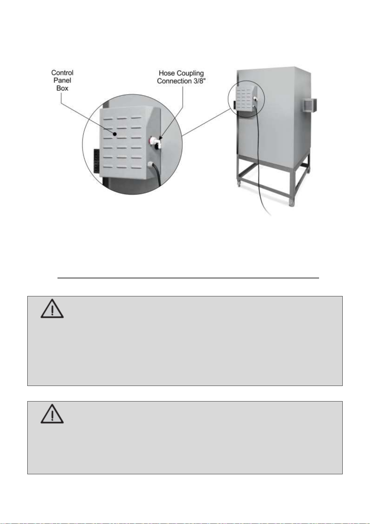
The power cable for the oven model with 220 V single-phase connection has three wires
(Ground, Phase and Neutral), the model with voltage 220 V three-phase connection with four wires
(Ground and Phases RST) and voltage 380 V three-phase connection has 5 wires (Ground, Neutral
and RST Phases).
For cables that have Neutral, their color is blue and is labeled with a sticker. It is mandatory to
connect the neutral wire to the neutral of the mains.
If the power cord is damaged, it must be replaced with a new one. The exchange must be made
by the manufacturer, authorized agent or a qualified person in order to avoid risk.
ATTENTION!
In order to avoid accidents, it is mandatory to connect the neutral wire to the neutral of the
power grid. And alsothe ground wire for all types of voltage, according to the current regulation.
Never connect the ground wire to the neutral wire of the mains, water pipes, gas pipes, etc.
For correct grounding, consider the instructions in standard NBR 5410 - ABNT.
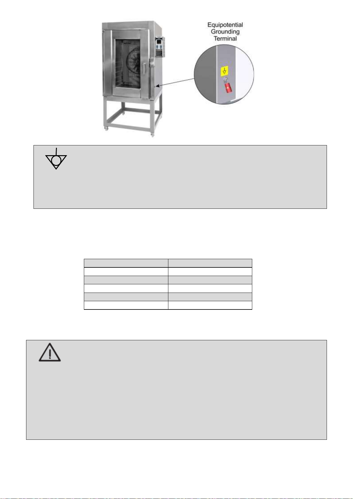
Accompanying the equipment, an equipotential grounding terminal (Electric Terminal), located on
the right-hand side of the oven.
14
The Electric Terminal identified in the figure below is an additional rotection
for the grounding that is provided in the mains. It must be connected to a
grounding terminal bar, regardless of the connection to the mains, and ther
products that have accessible metallic parts. And which are stationary, must also be
connected to this bus as well as the service bench itself, in case it is of metallic material . In
this way all these products will be under the same electrical power avoiding undesirable
leaking currents.
For your safety, the equipment must be connected to an exclusive 15 A thermoelectric circuit
breaker within a maximum distance of 1.5 m of the oven.
Below is the breaker table for each oven model:
Model
Circuit Breaker (A)
FTE150 –220 V MF
50
FTE150 –220 V TF
25
FTE150 –380 V TF
16
FTE300 –220 V TF
50
FTE300 –380 V TF
32
The ovens described in this manual are single voltage, ie 127 V, 110 V or 220 V. If you need to
change the voltage in your equipment, contact the manufacturer or your authorized dealer.
ATTENTION!
Before turning on your equipment, always check that the mains supply voltage is the same as
the equipment voltage. If it is not the same, contact the manufacturer or authorized dealer.
The supply voltage of this equipment is 220 V (50 or 60 Hz) single-phase or 220 V and 380 V
three-phase (50 or 60 Hz), as can be verified on the voltage label affixed to the power cable or
as indicated on the nameplate data label, which is located on the right side of the equipment
(see the figure on this label in item 2.2 of this manual).
Make sure that the voltage of the electrical network where the equipment will be installed is
compatible with the voltage indicated on these labels.
For more details on the rest of the electrical part of the equipment, refer to the electrical diagram
in the annexes of the manual.

15
IMPORTANT
The manufacturer is not responsible for possible direct or indirect damages caused by non-
compliance with said standards and other instructions presented in this manual.
3.4 Safety Procedures and User Instruction
The professional who sells the equipment must instruct the user on its correct operation and must
deliver this instruction manual.
The user must be informed of the necessary safety measures and must respect them, as well as
all the measures described in this manual.
Your equipment has mechanical protections (see item 1.2 Mechanical Safety) and a safety
system that prevents the turbine from running and heating if the door is open. Removing or tampering
with these safety components can cause serious risks to the operator.
ATTENTION!
Before using your equipment, check the direction of rotation of the turbine. For this, position
yourself in front of the oven, the turbine must be turning counterclockwise, as shown in the
following figure.
In case of any irregularity, contact the nearest authorized technical assistance servisse.
4. Use of Equipment
4.1 Utility
This equipment is intended to bake breads, pizzas, snacks and confectionery products in general.

16
4.2 Commands
The equipment consists of controller, power button and on / off switch light. The controller and
buttons are located on the front panel of the control panel.
See description of each command below:
•Power Button - used to turn the equipment on and off. In position "1" turns on, in position "0" turns
off.
•Power Button Light - used to turn the light located on the oven door on and off. In position "1" turns
on, in position "0" turns off.
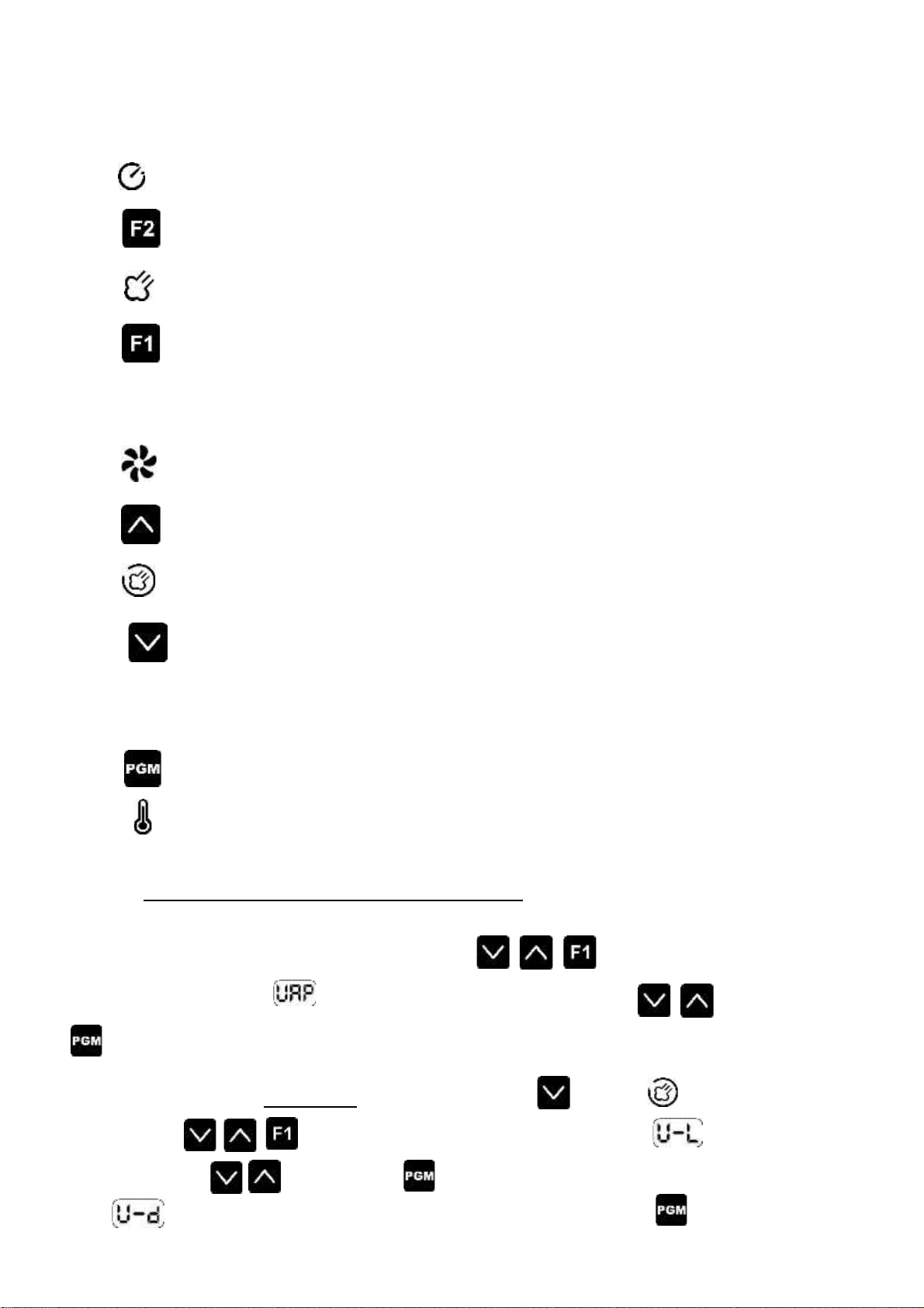
•Controller - Used to program temperature, cooking time and steam. The following is the description
for each function:
17
1 - Display that indicates the temperature present in the temperature sensor or the programmed
temperature;
2 - Display indicating elapsed time or programmed time;
3 - Led timer indicator;
4 - Timer key: activates or cancels the timer;
5 - Steam output indicator light on;
6 - Single steam time trigger button. At each touch the steam output is activated for a
preset time (factory setting is 6 seconds). To reprogram the cyclic steam, follow the
instructions below;
7 - Led indicating whether the fan is energized;
8 - Up key: increases the programmed value and activates the fan;
9 - Led indicating cyclic steam enabled;
10 - Down key: decreases the programmed value and selects the cyclic steam function,
which emits steam automatically for 6 seconds and every 2 minutes (factory default program). To
reprogram the cyclic steam, follow the instructions below;
11 - Programming access key;
12 - Heating indicator LED on;
Reprogramming of single steam and cyclic steam:
To reprogram the steam time press the keys at the same time, in that moment
it will appear in the display . Set the the steam time through the keys . Press the button
to confirm the simple steam program.
Reprogram the cyclic steam by pressing the button , the led will light up. After that,
press the keys at the same time and the display will appear . Set the steam exit
time with the keys and confirm that it will also activate the time option for each steam
cycle . After setting the interval time between each cycle, confirm with .
18
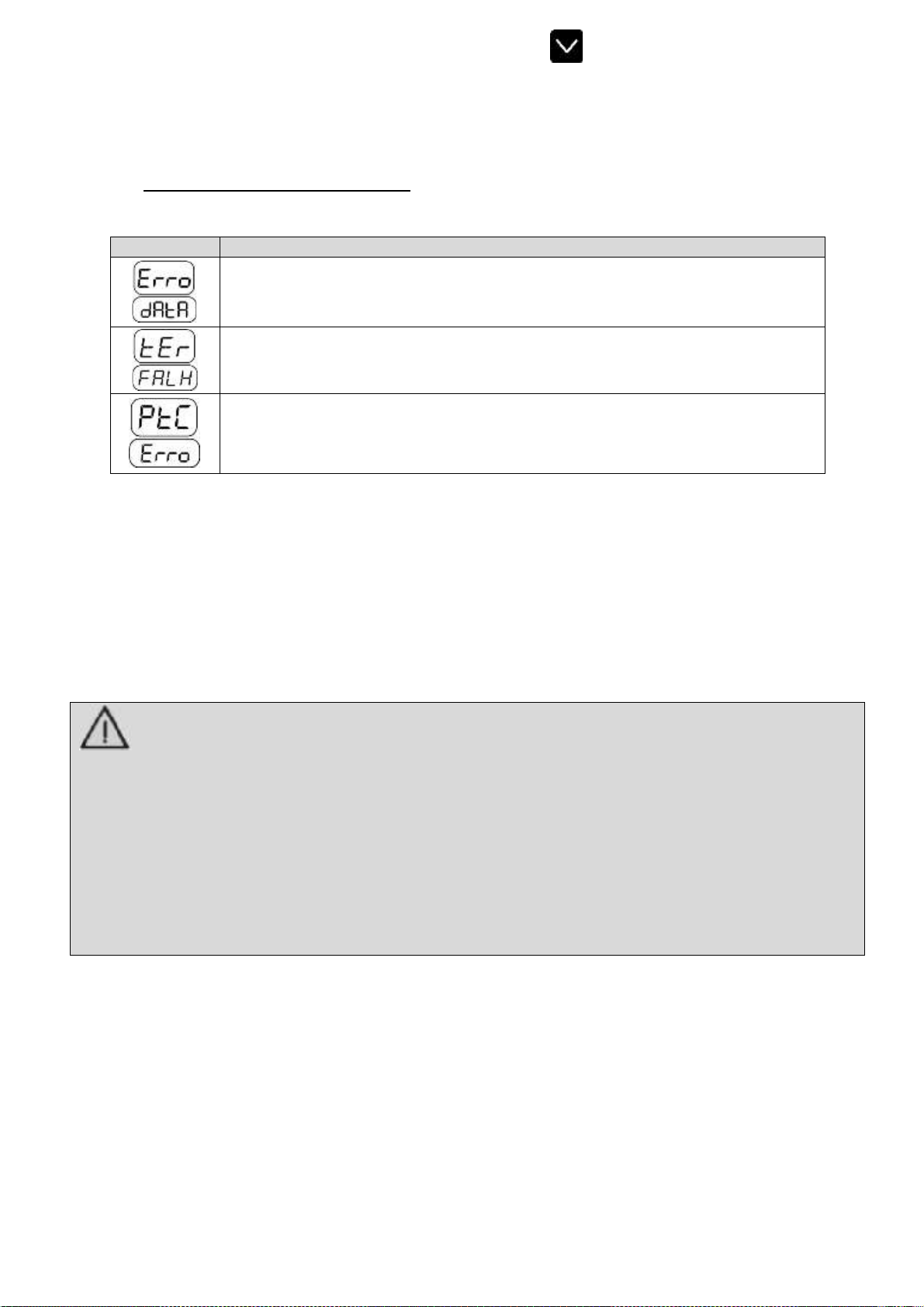
To deactivate the cyclic steam function, press the key .
The controller has a system that checks for possible faults in the temperature sensor. This fault
can be seen on the display.
Check the description of the failure:
Display
Descrição
Some corrupted configuration parameters were detected and for safety all of
them were restored to their factory value. The user must turn the controller off
and on to return to operation.
The controller detected a failure in the temperature sensor. Verify that the
sensor is properly connected to the controller and that the sensor is not
damaged.
The controller has detected that the temperature measured by the PTC sensor
is above normal operating conditions. Check that the sensor is properly
connected to the controller and that it is not broken or damaged.
4.3 Operating Procedures
Before operating the equipment, make the perfect cleaning, especially inside the oven.
Clean the equipment with the oven at room temperature and disconnected from the mains. Follow the
cleaning instructions in item 5 of this manual (below).
ATTENTION!
For the first use of model equipment FTE.150 and FTE.300 (models with carbon steel chamber
with high temperature paint finish) it is necessary to cure the paint inside the oven (chamber).
To do this, the empty oven must be switched on and the temperature raised to 220° C for a
minimum of 60 minutes. Follow the operating instructions in the following operation item.
During the curing process of the paint, odor and smoke will be released due to the burning of the
paint.
Turn off the machine and wait until the oven is at room temperature. After that your equipment
will be available for use.
•Operation: The equipment can only be operated after checking the correct arrangement of the
equipment, instructed in item 3.1, and after following the precautions and recommendations of the hydraulic
installation,electricalconnectionandgasinstallation,accordingtotheinstructionsinitems3.2,3.3and3.4.
Check the following operating instructions:
1. If you have installed a water valve, make sure it is open;
2. Turn the power switch to "1" (on) and wait until thetemperature display show the set temperature;
19
ATTENTION!
The Oven leaves the factory with temperature programmed at 200° C and cooking time 60 minutes. Due
to this programming, as soon as the on / off button is pressed the oven starts the heating and rotation
of the turbine.
To reprogram the cooking temperature and time, follow the instructions below.
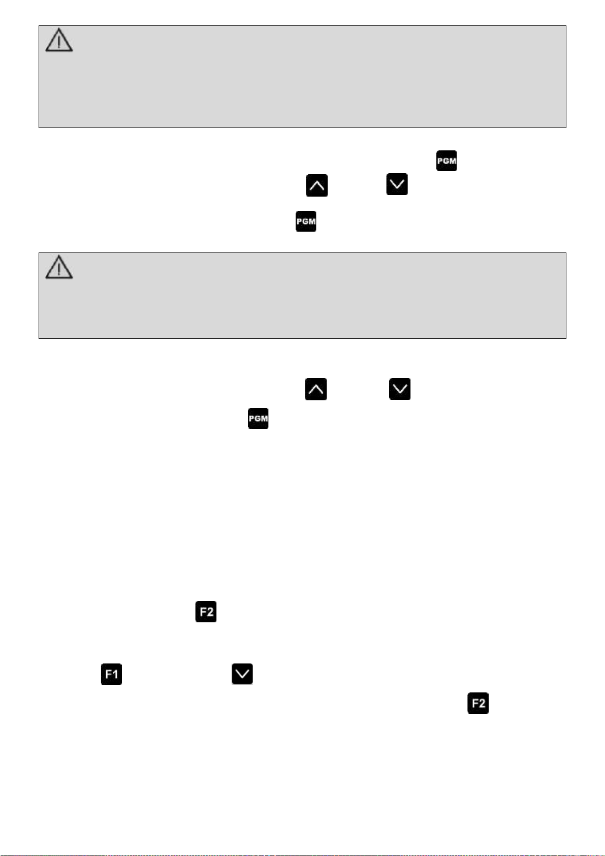
3. Start the oven programming by pressing the programming access key ;
4. Enter the desired temperature using the up and down keys. The selected value will
appear on the temperature display.
5. To confirm the temperature press the key ;
ATTENTION!
For your safety and not to compromise the life of the equipment, the maximum temperature supported
by the oven is up to 250° C.
Failure to observe this guideline will be considered as unsafe act and abusive use of equipment.
6. After confirming the temperature, the time display will be available for programming. Enter the
desired cooking time in minutes using the up and down keys;
7. To confirm the time press the key ;
8. After the oven reaches the desired temperature, open the oven door. At this point it will
automatically switch off the fan and the oven heating due to a safety system;
Only with the door open is possible switched off the turbine with the oven switched on.
9. Place the perforated racks (dimensions 580 x 700 mm) inside the oven. As soon as you close
the door, the fan and the heating will switch on automatically without the need to reprogram the
temperature and the time. Make sure the door is firmly closed by turning the knob to the limit of
its stroke;
to activate the preprogrammed cooking time count as instructed from10. Press the timer button
item 6;
11. After the heating reaches 100°C, the use of the steam function is released. If necessary, press the
key for manual steam or for cyclic steam according to your recipe;
12. At theend ofthe set time,a beep sounds. To turnthe beepoff, pressthe button ;
13. Open the door and remove the racks. To insert more racks using the same temperature and
time, repeat the instructions from item 9. If the food to be roasted needs reprogramming of
temperature and time, follow the instructions from item 3;

24
14. After the work is finished, turn off the machine by pressing the power button in the "0" (off) position;
15. Before cleaning your machine, wait until the inside of the oven reaches room temperature.
•Temperatures:
Temperature Table and Cooking Time
Product
Temperature (°C)
Time (min.)
French bread
170 / 180
15 / 20
Sweet bread
140 / 150
25 / 30
Cake
160 / 170
20 / 25
Pizzas
180 / 200
10 / 15
ATTENTION!
Always use appropriate PPE (Personal Protective Equipment) when using your equipment to
prevent accidents, such as burns due to oven heating.
IMPORTANT
The manufacturer shall not be liable for any direct or indirect damages caused by non- compliance
with these standards and other instructions presented in this manual.
5. Cleaning and Maintenance
5.1 Cleaning Procedures and Products Used
Your equipment is built with first-line materials, so use it correctly and you will get great
satisfaction. Keep your equipment always clean and well taken care of, as this will make it have a
much longer shelf life.
A daily cleaning of the equipment should be carried out in order to obtain a good functioning,
greater durability and avoiding the accumulation of bacteria that may cause contamination in the food.
ATTENTION!
Before performing maintenance or cleaning, make sure that the power switch is in the "0"
(off) position, that the equipment is disconnected from the mains and the inside of the oven at
room temperature.
Never clean the door glass with the oven still heated, as it may break due to thermal shock.
ATTENTION!
Do not use water jet to clean the equipment.
This manual suits for next models
3
Table of contents


