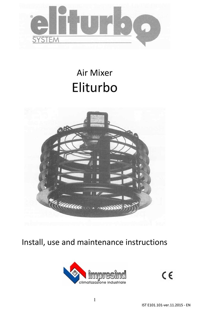
Impresind Eliturbo E.L.C. series Operating instructions

ELITURBO SYSTEM
Section 0 – General information
Index
SECTION 0 – GENERAL INFORMATION ..................................................................................3
Information for the user ................................................................................................................................. 4
SECTION 1 – TECHNICAL CHARACTERISTICS.....................................................................5
1.1 Identification data of the product............................................................................................................. 5
1.2 ELITURBO ® air mixer introduction ....................................................................................................... 5
1.3 Technical characteristics.......................................................................................................................... 6
1.3 Expected use ............................................................................................................................................ 6
1.6 Switchboards............................................................................................................................................ 7
1.7 Improper use ............................................................................................................................................ 7
SECTION 2 – PACKING, LOGISTIC AND TRANSPORT.........................................................8
2.1 Equipment receiving ................................................................................................................................ 8
2.2 Logistic and transport .............................................................................................................................. 8
2.3 Lifting ...................................................................................................................................................... 8
2.4 Unpacking................................................................................................................................................ 9
2.5 Storage ..................................................................................................................................................... 9
SECTION 3 – INSTALLATION AND TESTING .......................................................................10
3.1 General warnings for installation........................................................................................................... 10
3.2 Positioning the Eliturbo ......................................................................................................................... 10
3.3 Electric network connection .................................................................................................................. 12
SECTION 4 – PROTECTION SYSTEMS ....................................................................................15
4.1 Protection devices .................................................................................................................................. 15
4.2 Clothing ................................................................................................................................................. 15
4.3 Residual risks......................................................................................................................................... 15
4.4 Emergency situations............................................................................................................................. 15
SECTION 5 –PRODUCT USE .......................................................................................................16
5.1 Switching on/off the product ................................................................................................................. 16
5.2 Reccomendations for the user................................................................................................................ 16
5.3 Stop of the system at the end of the season............................................................................................ 16
5.4 Functioning anomalies........................................................................................................................... 16
5.5 Signs applied on the product.................................................................................................................. 16
SECTION 6 – MAINTENANCE ....................................................................................................17
6.1 Maintenance security norms .................................................................................................................. 17
6.2 Technical assistance requests................................................................................................................. 18
SECTION 7 – DISMANTLING .....................................................................................................19
7.1 Dismantling............................................................................................................................................ 19
2
IST. E101.101GB –- ed. 11/08

ELITURBO SYSTEM
Section 0 – General information
SECTION 0 – GENERAL INFORMATIONS
INTRODUCTION
Dear Client,
We thank you to have chosen an Impresind Srl product and inform you that:
• The aim of this guide is only informative and can be subject to variations without warning;
• This guide cannot be nor partially nor entirely reproduced, diffused, copied or saved in a
storage system in any form or in any media, mechanic, magnetic, optic, chemical or others,
without written authorisation by Impresind Srl.
• This guide has to be conserved until the final dismantling of the product, in case of property
change the guide has to be delivered to the new owner.
• In case of damage and consequent block of the product, Impresind Srl doesn’t refund
eventual economical losses due to the forced block of the product and doesn’t extend the
warranty.
For easy consultation, the guide has been divided into sections, each one is represented by a
symbol:
Section 0→General information.
Section 1→Technical characteristics, description of the product and its
application field, and standard and optional equipments.
YSection 2 →Packing, logistic and transport.
°
Section 3 →Installation and testing.
3
IST. E101.101GB –- ed. 11/08

ELITURBO SYSTEM
Section 0 – General information
a
Section 4 →Protection systems
Section 5 →Product use.
#
Section 6 →Maintenance.
Section 7 →Dismantling.
Information for users
This guide is an integrant part of the product and has to be accessible easily by the user and
maintenance-authorised personnel.
The use and maintenance authorised personnel is obliged to know the contents of this guide’s
sections before the product is put into function.
In case of loss or damage of the guide a copy of it has to be requested immediately by contacting
the Technical Assistance of Impresind Srl, keep handy the identification data of the system printed
on the product’s data plate and on the cover of the guide.
The product is in accordance with the following community directives:
2006/42/CE ⇒Machine Directive
2006/95/CE ⇒Low Voltage Directive
2004/108/CE ⇒Electromagnetic Compatibility Directive
IT IS ABSOLUTELY FORBIDDEN TO MODIFY THE PRODUCT AND ITS
APPLICATION FIELD.
Impresind Srl declines any responsibility for damages that could, directly o
r
indirectly, derive by people or objects, due to improper use of the product o
r
different use from its application field, incorrect installation, not appropriate
s
upply used, modified or different installation environment than the one
communicated in the order stage, bad maintenance deficiencies, no
t
authorised interventions and modifications, use of non original spare parts,
removal of active and passive protections, non observance of the use
r
instructions carelessness, etc.
4
IST. E101.101GB –- ed. 11/08

ELITURBO SYSTEM
Section 1 – Technical characteristics
SECTION 1 – TECHNICAL CHARACTERISTICS
1.1 Identification data of the product
The main identification data of the product (serial number, model, etc) is stated on the data plate
positioned on the product.
Data plate
In case of technical assistance or spare parts request, the products
model and serial number have to always be communicated.
1.2 ELITURBO ® AIR MIXER INTRODUCTION
Eliturbo®is an air mixer that is able to horizontally and vertically even the air temperature, to even
the humidity inside large environments and to reduce the costs of heating.
Eliturbo® uses a special helicentrifugal rotor patented by Impresind Srl that generates air mixing, it
does not create currents that bother workers, it is manufactured in accordance with the security
norms and the environment’s hygiene norms.
The Eliturbo®air mixer, differing from the other ceiling ventilators, doesn’t direct air fluxes
directly down and in concentrated areas, but it distributes the air in a radial way influencing large
areas with an imperceptible ventilation.
The air stratification phenomenon and heat accumulation near the ceiling, in large volume heated
environments, is very common and is the cause of big heat dispersions and high energetic costs.
An Eliturbo®air mixer system prevents hot air stratification, reduces the energetic consumptions
and the environment comfort.
Eliturbo®’s exclusive air mixing improves the environment conditions even during the summer
season when, caused by high temperature and high percentage of relative humidity, a micro climate,
intolerable by personnel and structures, is generated.
5
IST. E101.101GB –- ed. 11/08

ELITURBO SYSTEM
Section 1 – Technical characteristics
The Eliturbo®air mixer creates a constant air exchange through the open windows and other
openings, keeping an active ventilation of the environment.
1.3 Technical characteristics
Eliturbo series E.L.C. 2000 2002
Engine type (Size) 71 71
Absorbed power W 200 300
Frequency Hz 50
Tension V 230/400
Voltage A 1,7/1
Rotor type helicentrifugal
Fan type - 2
Rotor version n. blades 2 4
Treated air m3/h 7500 10000
Speed Rpm 700
Diameter mm 680
Height mm 570
Weight kg 16 18
External finishing Epoxy powder paint
Colour black
Table 1 – Technical characteristics
1.3 Expected use
Eliturbo®can be installed in any environment where it is necessary to have air mixing, for example:
• Production and commercial premises, warehouses
• Zootechnical farms;
• Swimming pools, tennis courts and other sport structures;
• Green houses and floriculture structures;
• Churches, libraries, museums, fair pavilions, etc.
6
IST. E101.101GB –- ed. 11/08

ELITURBO SYSTEM
Section 1 – Technical characteristics
It is not allowed, for any reason, to use the product for a different scope than
the one it was studied for, nor to use the product in a different way of the one
described in this guide.
During the use of the product do not touch the ventilator – Mechanical
danger.
1.6 Switchboards
The switchboards, eventually, supplied by Impresind Srl are realised in specification to the EN
60204/1 norms.
IT IS ABSOLUTELY FORBIDDEN TO MODIFY THE
SWITCHBOARD
IT IS ABSOLUTELY FORBIDDEN TO ESTINGUISH FIRES WITH
WATER
1.7 Improper use
The unit can’t be used for different scopes than the ones stated in the paragraph 1.3 of this
guide.
IT IS ABSOLUTELY FORBIDDEN TO INSTALL THE ELITURBO AI
R
MIXER IN ENVIRONMENTS WITH DANGER OF EXPLOSION AND
HIGHLY INFLAMMABLE MATERIALS.
IN CLOSED PREMISES, WHERE THERE IS A HIGH CONCENTRATION OF
HALOGEN VAPOUR, IT IS SUGGESTED NOT TO INSTALL EITURBO
UNITS. REGARDING THIS SUBJECT IT IS SUGGESTED TO PAY
PARTICULAR ATTENTION TO THE ENVIRONMENTS DEDICATED TO:
LAUNDRY, DRY CLENING, TYPOGRAPHY, COIFFURE, COSMETIC
SALOON.
7
IST. E101.101GB –- ed. 11/08

Y
ELITURBO SYSTEM
Section 2 – Packing, logistic and transport
SECTION 2 – PACKING, LOGISTIC AND TRANSPORT
2.1 Equipment receiving
When the package is delivered to the client, the latter is obliged to control the integrity of the
product.
2.2 Logistic and transport
Control the package an its contents, in case o
f
damage due to the transport, the client has to
tick damage claim box on the transpor
t
document, counter signed by the carrier an
d
s
end a copy via fax to Impresind Srl.
Pay high attention in handling the Eliturbo®units during the phases of:
downloading from the carrier, lo
g
istics and positioning, to avoid damages to
the unit.
IMPRESIND SRL DECLINES ANY RESPONSABILITY FOR DAMAGES
DUE TO TRANSPORT, UPLOAD, DOWNLOAD OF THE ELITURBO®
UNITS
Move Eliturbo®units with maximum care, avoid to interfere with the ventilator.
2.3 Lifting
Ensure that the maximum lifting power of the lifter is adequate to the
p
roducts weight.
The product has to be lifted only by qualified personnel.
IT IS ABSOLUTELY FORBIDDEN TO STAY UNDER THE HANGING
LOADS AND INSIDE THE ACTION AREA OF THE LIFTE
R
It is suggested to handle the Eliturbo®air mixer by the top
s
upports avoidin
g
to interfere with the circular deflectors.
A
void touching with the hands the rotor: deformation danger and consequen
t
unbalanced functioning of the air mixer.
8
IST. E101.101GB –- ed. 11/08

Y
ELITURBO SYSTEM
Section 2 – Packing, logistic and transport
2.4 Unpacking
Carry the Eliturbo®units in the installation area.
Free all the wrapped components from the packaging and collect everything to prevent the potential
danger of fire and suffocation of people or animals.
The discharge of the packaging material has to be done in specification to
the norms in force in the destination Country of the Eliturbo®.
2.5 Storage
The temperature during transport and storage has to be between -10 and 50 °C.
Whenever the Eliturbo®units are stored, it has to be ensured that the relative humidity in the
storage is between 5% and 95%.
9
IST. E101.101GB –- ed. 11/08

°
ELITURBO SYSTEM
Section 3 – Installation and testing
SECTION 3 – INSTALLATION AND TESTING
3.1 General warnings for installation
Before proceeding with the installation of the Eliturbo units, it is necessary to check if all the
components have been unpacked and their integrity controlled.
The laying and installation of the Eliturbo®units has to be done by qualified personnel and
following the indications of the lasws in force in the destination Country of the units.
The air mixers are provided with different direction of rotation, identified by different colour arrows
applied on the unit and the packaging.
Clockwise rotation
Anti clockwise rotation
When installing, it is important to follow a chess board global positioning of the units, so that two
near units have always opposite rotations.
The choice of the rotation of the first unit is not important, as long as the following units are
installed with alternate rotations; it is not important what is the rotation of the last unit.
3.2 Positioning the Eliturbo
Lifting machines for personnel and materials have to be available in the installation area and have
adequate lifting power. For information on the security norms to be observed during lifting refer to
the paragraph 2.3 of this guide.
10
IST. E101.101GB –- ed. 11/08

°
ELITURBO SYSTEM
Section 3 – Installation and testing
It is suggested to hang the Eliturbo®units from the ceiling or from a beam, at a minimum distance
equal to at least 15% of the entire height of the environment, in any case not lower than one meter.
For example:
Ceiling height (meters) Hanging height (meters)
6 5
8 6,5 ÷ 7
10 8 ÷ 8,5
14 11 ÷ 12
For a quick installation it is suggested to use chaines.
To lift people the machinery has to be specifically certified and used b
y
qualified personnel.
The personnel that will be working at heights has to be previously trained,
wear and use individual protection media to respect the legislation in force,
s
afety shoes, gloves, protection helmet, harness, etc.
Before positioning the unit, verify that it will not interfere with existin
g
machineries as lifters, kranes etc.
A
void positioning the unit near scaffolding, racks,etc..
In case of accessible scaffolding, verify that the unit is positioned at leas
t
2,5m from the scaffolding.
To anchor the unit to the ceiling use steel chains with a minimum diameter o
f
3.5 mm or use steel cables with minimum diameter of 4.0 mm
The anchor points have to be at a sufficient distance to contrast the starting torque; it is suggested to
apply the anchoring points in a way that the chains will form an angle of 30° ÷40° from the
vertical.
The length of the sustaining devices has to be at least a meter, this is to guarantee this distance
between the anchor point and the Eliturbo®’s engine.
The sustaining devices have to support a weight equivalent to 10 times the weight of the unit
distributed on the anchor points (at least 100 Kg for each anchor point: on two anchor points).
The Eliturbo® air mixer does not have to be installed at less than 2,5 m from
the floor.
11
IST. E101.101GB –- ed. 11/08

°
ELITURBO SYSTEM
Section 3 – Installation and testing
Ensure that the installation is done respecting a perfect horizontal plane.
3.3 Electric network connection
The electric network connection has to be done by qualified personnel.
A
ll the components used for the connection have to be certified. Before
operating on the power cables ensure that the network was severed.
Ensure an efficient connection of earthing using the
s
pecific terminals.
The foreseen power is:
- 230 V ∼50 Hz For units with single phase engine
- 400 V 3 ∼50 Hz For units with three phase engine
The electric network has to be done in specification to the norms in force.
It is possible to foresee a switchboard of command from which start power cable of each mixer.
12
IST. E101.101GB –- ed. 11/08

°
ELITURBO SYSTEM
Section 3 – Installation and testing
A safety motor switch has to be inserted between each Eliturbo®air mixer and the electric network,
it has to have a minimum distance between the contacts of at least 3mm for each pole, they have to
be inserted in a position easily reachable by the user.
Any engine has to be protected with a correct protector calibrated at a voltage of 1,1 I1,15 times
the voltage indicated on the data plate.
If the switchboard has a speed adjuster just follow the switchboard’s instructions.
V2U2
W1V1
W2
U1
capacitor *
V2W2 U2
W1V1U1
CONNECTION WHIT ELECTRICAL SUPPLY SINGLE PHASE : V.230 - 50 Hz.
right hand clockwise
V.230 - 50 Hz
*CAPACITOR: CHECK VALUE ON PLATE LABEL ON ENGINE
V2W2 U2
W1U1 V1
L3L1 L2 V.400 - 50 Hz
TO REVERS THE ROTATION: EXCHANGE PHASES ( L1 ÷ L2 )
left hand anticlockwise
capacitor *
CONNECTION WHIT ELECTRICAL SUPPLY THREE PHASE : V.400- 50 Hz.
3.4 Functioning test
Before starting the ventilator verify that the hanging systems (chains, fischers, etc.) are properly
fixed, the product is perpendicularly , and that the electrical power cables don’t interfere with the
movement of the rotor.
Start the ventilator and verify that:
• the direction of rotation is correct (see the sense indicated by the arrow on the product)
• that the product does not do strange noises: in this case stop immediately the engine by
cutting off the electric power that supplies the product and search for the cause of the noise
13
IST. E101.101GB –- ed. 11/08

°
ELITURBO SYSTEM
Section 3 – Installation and testing
• the product does not have an excessive vibration due to the unbalance of the girante: in this
case stop immediately the engine by cutting off the electric power that supplies the product
and refer to the Technical Assistance of Impresind Srl
• do not start the product if is shows any of the anomalies stated above
To invert the direction of rotation of the engine, after cutting off the electric power that supplies the
product, follow the steps below:
Single phase engine⇒connect the motor terminals by following the instructions stated in the
electric scheme
Three phase engine⇒exchange the position of the two phase (example. R – S).
14
IST. E101.101GB –- ed. 11/08

a
ELITURBO SYSTEM
Section 4 – Protection systems
SECTION 4 –PROTECTION SYSTEMS
4.1 Protection devices
To comply with the dispositions of the Community Directives applicable to the unit that this guide
is referred to, Impresind Srl has predisposed on the unit the security systems requested by the
existing legislation.
4.2 Clothing
As the product cannot be installed at normal working height and is not reachable by the users during
normal activities, there is not any particular clothing prescription for the personnel.
The maintenance personnel are obliged to wear specific clothing and to use personal protection
devices.
4.3 Residual risks
Pay attention to the movement of the ventilator. Do not introduce limbs –
Mechanical danger
Use of water to clean is forbidden –Electrocution danger
4.4 Emergency situations
In case of emergency:
• Stop immediately the engine and open the electric circuit with the
main switch
• Identify and eliminate the problem controlling the original causes
• Contact the Technical Assistance of Impresind Srl
IT IS ABSOLUTELY FORBIDDEN TO USE WATER TO ESTINGUISH
FIRES
ONLY USE POWDER OR CARBON DIOXIDE FIRE ESTINGUISHERS
15
IST. E101.101GB –- ed. 11/08

ELITURBO SYSTEM
Section 5 – Product use
SECTION 5 – PRODUCT USE
5.1 Switching on/off the product
Switch on/off the products with the switch or the switchboard, the client can arrange the installation
of a clock switch that automatically will switch on and off the product in the established hours.
5.2 Recommendations for the user
Start the Eliturbo 15/30 minutes before the heating system.
Switch off the Eliturbo 30 minutes after the heating system; eventually anticipate the closure of the
heating system.
Do not, for any reason, apply an environment thermostat to the commands of the Eliturbo®air
mixer. The Eliturbo®air mixer has to work constantly to contrast the natural elevation of hot air to
the ceiling.
For a better management of the system and to achieve energetic savings it is necessary that the
heating system has an environment thermostat positioned at 1,5 meters of height.
5.3 Stop of the system at the end of the season
At the end of the use period, the system can be stopped by cutting off the electric tension with the
general switch.
5.4 Functioning anomalies
In case of function anomalies:
• switch off the system;
• sever the electric supply;
• contact the Technical Assistance of Impresind Srl, the installer or a qualified technician.
5.5 Signs applied on the product
Electric organs with voltage ⇒indicates danger due to electric parts with voltage
Mechanical organs ⇒indicates danger due to mechanical part in movement
16
IST. E101.101GB –- ed. 11/08

#
ELITURBO SYSTEM
Section 6 – Maintenance
SECTION 6 – MAINTENANCE
6.1 Maintenance security norms
Maintenance personnel doesn’t have to wear clothes with large sleeves, laces or belts that could
cause danger; furthermore, they have to use the personal protection devices in specification to the
legislations in force.
Before the beginning of the heating season it is necessary to verify that the product works properly,
so that in case of malfunctioning there is time to do eventual maintenance/repairs.
Check once a year:
• The electric system’s security, absorption, dissipation;
• that the hanging devices are well anchored;
• stability and balance of the helicentrifugal rotor (no big vibrations have to be detected);
• cleanness of the rotor’s blades (in dusty or humid environments incrustation can form, this
will the rotor heavier obliging the engine to do excessive work);
• generic cleanness of the air mixer.
During maintenance, expose the “work in progress” signs in a way that they are visible by all access
areas.
Record on a register all the maintenance carried out, making sure to sign: date, hour, type of
maintenance and name of the personnel that carried out the maintenance.
The eventual use of cleaning solvents has to be done without touching the electric cables.
Maintenance personnel have to be qualified.
Before applying any maintenance operation, carefully read this section of the
g
uide. For any necessity contact the Technical Assistance of Impresind Srl.
Impresind Srl declines any responsibility for any damage or dysfunction i
f
due to lack of application of the indications in this section of the guide
The producer declines any responsibility for damages due to non
-
observance of
the prescription, to an incorrect installation and in case of improper use of the
product by the user.
The maintenance personnel that use cleaning solvents have to use the
p
ersonal protection devices (security goggles, filter mask, gloves) for the
contact with the solvent. During the use of solvents, it is forbidden to smoke
and use free flames. When finished cleaning air properly the premise to
discharge the remaining vapours.
17
IST. E101.101GB –- ed. 11/08

#
ELITURBO SYSTEM
Section 6 – Maintenance
IT IS FORBIDDEN TO:
• DEPOSIT COMBUSTION MATERIALS NEAR THE
SWITCHBOARDS
• OPERATE ON THE ELECTRIC PARTS WITHOUT HAVING
PREVIOUSLY SELECTED THE ELECTRIC SUPPLY LINE
• OPERATE ON ANY PART OF THE UNIT WITHOUT HAVING
SWITCHED OFF THE SYSTEM
• OPERATE WITH THE SECURITY SYSTEMS DEACTIVATED O
R
DISCONNECTED
• DEACTIVATE OR TRICK THE ALARM SIGNALS APPLIED ON
THE PRODUCT
• USE THE PRODUCT WITH THE METALLIC PROTECTIONS
REMOVED.
• IGNORE THE WARNINGS AND SIGNS APPLIED ON THE UNIT
Once finished the maintenance, before restoring the electric supply and switch on the system,
accurately control that no equipment and/or various materials have been forgotten near or inside the
unit and especially near moving organs.
18
IST. E101.101GB –- ed. 11/08

ELITURBO SYSTEM
Section 7 – Dismantling
SECTION 7 – DISMANTLING
7.1 Dismantling
The dismantling of the system has to be done by specialised personnel with
correct instruments and personal protection devices.
Do not smoke and not use free flames
In case of dismantling or alienation of the system, it is necessary to recover all the materials and
send them to the respective collection centres, possibly referring to specialised companies.
19
IST. E101.101GB –- ed. 11/08
Other manuals for Eliturbo E.L.C. series
1
This manual suits for next models
2
Table of contents
Other Impresind Fan manuals
Popular Fan manuals by other brands
Jata
Jata VC3000 Instructions of use
Hunter Pacific
Hunter Pacific VortX V500i installation & warranty manual
Monte Carlo Fan Company
Monte Carlo Fan Company 3MO52 O-V1 Series Owner's guide and installation manual

Monte Carlo Fan Company
Monte Carlo Fan Company Prairie 14PRR52 D Series Owner's guide and installation manual
Harbor Breeze
Harbor Breeze Casual-3-2011 manual

LU-VE
LU-VE ALFA Optigo CD instruction manual

