IMRELAX IM-MH132 User manual
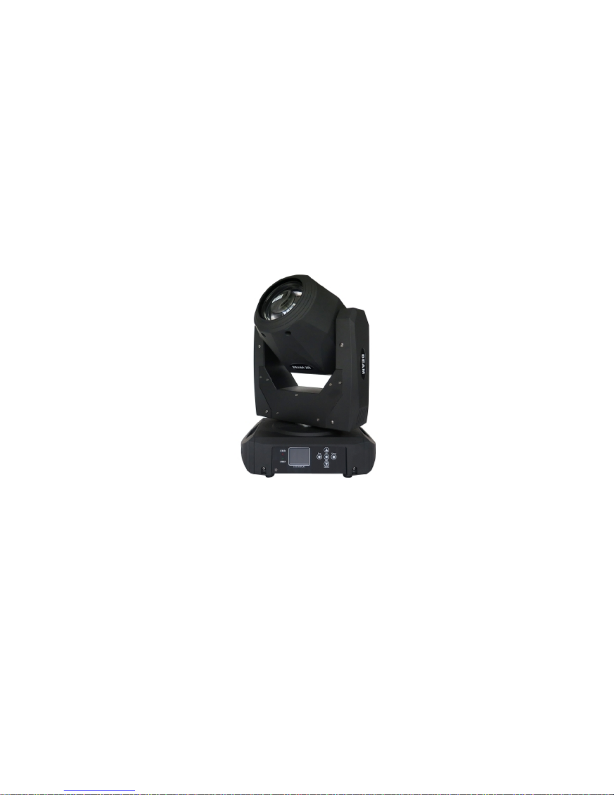
2R SHARPYBEAM MOVING HEAD
(IM-MH132)
USERMANUAL
Ver1.0

Table of contents
1. Preface 2
1.1 Packing list 2
1.2 Unpacking instructions 2
1.3 AC Power 2
1.4 Safety instructions 2
2. Introduction 3
2.1 Features 3
2.2 DMX channel 3
3. Setup 4
3.1 Fuse replacement 4
3.2 Fixture linking 4
3.3 3-Pin to 5-Pin conversion chart 4
3.4 Setting up a DMX serial data link 4
3.5 Master/Slave fixture linking 5
3.6 orientation 5
4. Operating instructions 5
4.1 Description of operation panel 5
4.2 Menu map 5
4.3 DMX channel values 7
5. Technical specifications 10

Pleaseread theseinstructions, it includes importantinformation aboutthe
installation, usage and maintenance of this product.
Warning! Verify that the voltage select switch on yourunit matches theline
voltageapplied. Damagetoyour fixture may result if the linevoltageapplied
does not match the voltageindicatedon the voltageselector switch. All fixtures
must be connected to circuits with a suitableEarth ground.
1. Preface
1.1 Packing list
Product name quantity
moving head light 1 pcs
Power -line 1 base
User manual 1pcs
1.2 Unpacking instructions
On receiving afixture, carefully unpack thecarton, check the contentsto
ensurethat all partsare presented, and have been received in agood
condition.Notify the shipper immediately and retainpackingmaterial for
inspectionif any partsappear damagedfrom shippingor the cartonitself
shows, sign of mishandling. Save thecartonandallpackingmaterials. In the
event that afixture must be returned to thefactory,it is important that the
fixture should be returned in originalfactory box and packing.
1.3 AC Power
Todetermine thepower requirementsfor aparticularfixture, see the label
affixed to the back plate of the fixture or referred to the fixtures specification
chart. Afixture listed current ratingis itsaveragecurrent drawunder normal
conditions. All fixtures must be directly poweredoffaswitched circuit and
cannot berun offarheostat (variable resistor) or dimmer circuit, evenif the
rheostat or dimmer sourcevoltage matchesthe fixtures requirement. Check
the fixture or device carefully to make sure that if avoltageselectionswitch
exists that it is set to the correct line voltage you will use.
1.4 Safety instructions
Pleasekeep this user guide for future consultation. If you sell theunit to
another user, be sure that they alsoreceive this instruction booklet.
Always make surethat youare connectingto the proper voltage, andthat the
linevoltage youareconnecting to is not higherthan thatstated on the decal or
rear panel of the fixture.

Before thefirst time to use it, Pleasecheck whether the damagein transit, if
happendamagesin transit, pleasedo not use this lamp, andpleaseasap
contact distributors or manufacturers.
Pleasedon't install the lamp in theordinary combustible materialonthe
surface. Lamp shouldbe installedinthe well ventilatedplace, and thedistance
of the wall to keepit over 10 cm, at the same time, please checkthe fan hole
was clear.
Do not use lamp direct project in flammableobjects, lamp andthe radiation
of the distance between theobjects please keep it over 12 m.
Do not use direct lamp project light source , toavoid damage the eyes.
Before installation,please make sure your use power supplyvoltageand
marked voltage
Note: beforeany install, maintain and clean lamp, please confirm cut off the
power supply.
2. Introduction
2.1 Features
Power 180W
16/20 channel DMX-512 .
Pan :540 /tilt:270 .
Variable electronic strobe.
Variable electronic dimmer(0-100%).
Beam angle:13.5
LCD display
Reset to factory settings option.
Pan/tilt inverts option.
Fan cooled.
2.2 DMX channel
CHANNEL
CHANNEL MODE
16 20
1 COLOUR WHEEL COLOUR WHEEL
2 STROBE STROBE
3 DIMMER DIMMER
4 GOBO WHEEL GOBO WHEEL
5 PRISM INSERTION PRISM INSERTION
6 PRISM ROTATION PRISM ROTATION
7 RESERVER RESERVER
8 RESERVER RESERVER
9 FOCUS FOCUS
10 PAN PAN
11 PAN FINE PAN FINE
12 TILT TILT
13 TILTFINE TILTFINE
14 RESERVER RESERVER
15 RESET RESET
16 LAMP CONTROL LAMP CONTROL
17 PAN-TILT SPEED
18 COLOUR SPEED
19 DIMMER-PRISM-FROST SPEED
20 GOBO SPEED
3. Setup
Disconnect the power cord beforereplacingafuse andalways replacewiththe
same type fuse.
3.1 Fuse replacement
With aflat head screwdriver wedge the fuseholdout of itshousing. Remove
the damaged fuse from itsholder andreplacewith exactsame type fuse. Insert
the fuse holder back in its place and reconnect power.
3.2 Fixture linking
You willneed aserial datalink to run light showof one or more fixtures using a
DMX-512 controlleror to run synchronized ontwo or more fixtures set to a
master/slave operating mode. The combinednumberof channels required by
all the fixtures on aserial datalink determinesthe number of fixtures the data
link can support.
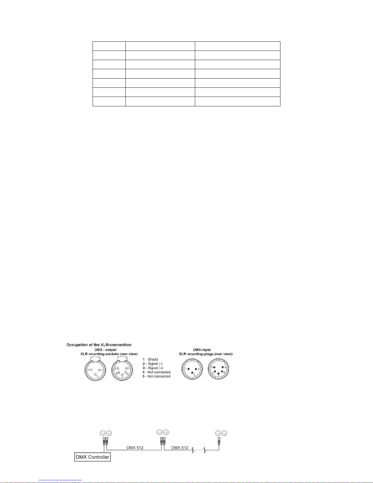
3.3 3-Pin to 5-Pin conversion chart
Note! If you useacontrollerwith a5pin DMX output connector.You will need
to use a 5pin to 3 pin as apter
CHAUVETModel No: DMX5M. Or DMX 5F
The chartbelow details a proper cable conversion:
3.4 Setting up a DMX serial data link
At first link the first light and DMX control through XLR-connectionsignal cable,
then connect the light in series, as the follow:
3.5 Master/Slave fixture linking
1. Connect the (male) 3pinconnector side of the DMX cableto the output
(female) 3pin connector of the first fixture.
2. Connect the endof thecablecoming fromthe first fixture which will have a
(female) 3pin connector to the input connectorof the next fixture consisting of
a(male) 3pinconnector.Then, proceed to connect fromthe output as stated
above to the input of the following fixture and so on.
3.6 orientations
This fixture may be mountedin any position providedthere is adequateroom
for ventilation.
4. Operating instructions
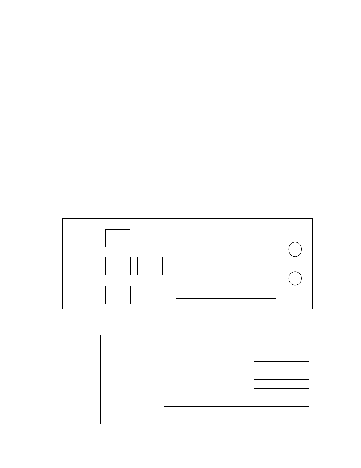
4.1 Description of operation panel
4.2 Menu map
Menu Setting
Run mode DMX
Soundcontrol mode
Perform 1
Perform 2
Perform 3
Perform 4
Random mode
DMX address 1-512
Channelmode 16 channel
20 channel
up
menu enter menu
down
DMX
ERR
Pan invert ON/OFF
Tiltinvert ON/OFF
Pan tiltswap ON/OFF
Code wheel ON/OFF
Signal timeout Blackout /keep
ScreensaveON/OFF
Lightup ON/OFF
Color linear ON/OFF
Factory ResetConfirm
Manual mode
Color 0-255
Strobe 0-255
Dimmer 0-255
Gobo 0-255
Prism 0-255
Prism rotate 0-255
Reserve0-255
Reserve0-255
Focus 0-255
Pan 0-255
Pan fine 0-255
Tilt 0-255
Tiltfine 0-255
Reserve 0-255
Reset 0-255
Blubcontrol0-255
(channel20)pan/tiltspeed 0-255
(channel20)color wheelspeed 0-255
(channel20)dimmer prism speed 0-255
(channel20)gobo wheelspeed 0-255
Offset
Pan offset 0-255
Tiltoffset 0-255
Color offset 0-255
Gobo offset 0-255
Focus offset 0-255
Prism offset 0-255
Dimmer offset0-255
Advance setting
Language switch Confirm
Screeninvert Confirm
Zero check Confirm
Lamp max hours xxxxx
Timezero clearing Confirm
Hardware information Pan coder wheel xx
Tiltcoderwheel xx

Pan sensorx
Tiltsensor x
Color wheelsensor x
Gobo wheel sensor x
Focus sensor x
Sensor4 x
Pan route xxxxx
Tiltroutexxxxx
Systeminformation
Version 160917081001
Use timeoffixture xxxxx
Turnon time xxxxx
Use timeofblub xxxxx
Error information
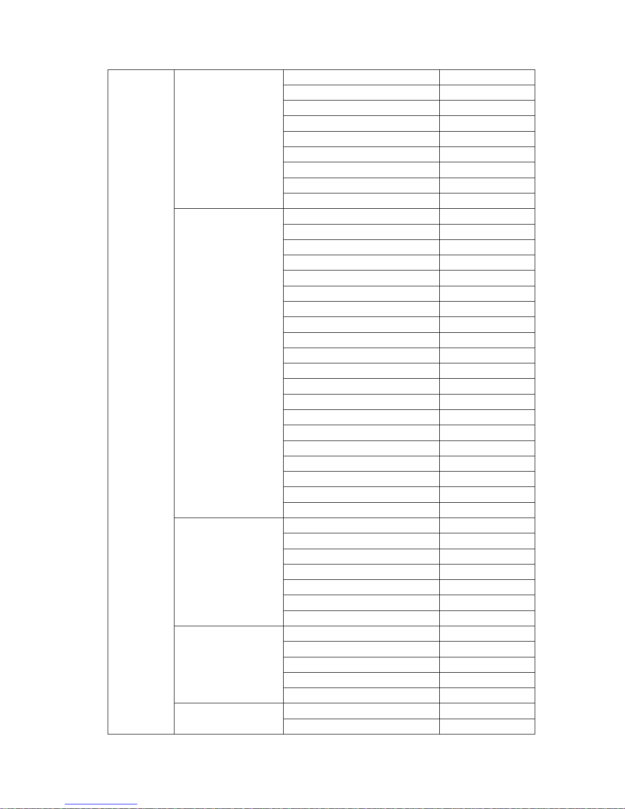
4.3DMXchannels
20
channel
16
channel
Function value description
1 1 Color 0-255 refer to color sheet
2 2 strobe
0-3 Blackout
4-103 common strobe fromslow to
fast
104-107 Open
108-207 pulse strobe from slow to fast
208-212 Open
213-251 random strobe from slow to fast
252-255 Open
3 3 Dimmer 0-255 increased brightness adjustment
4 4 Gobo 0-255 Refer to gobo sheet
5 5 Prism 0-127 Prism remove
128-255 Prism cut in
6 6 Prism rotate
0-127 Prism angle
128-190 Prism CW speed up
191-192 Prism stop rotate
193-255 Prism CCW speed up
7 7 Reserve
8 8 Reserve
9 9 Focus 0-255 Focus adjust
10 10 Pan 0-255 Pan move
11 11 Pan fine 0-255 Pan fine 16bit
12 12 Tilt 0-255 Tilt move
13 13 Tilt fine 0-255 Tilt fine16bit
14 14 Reserve
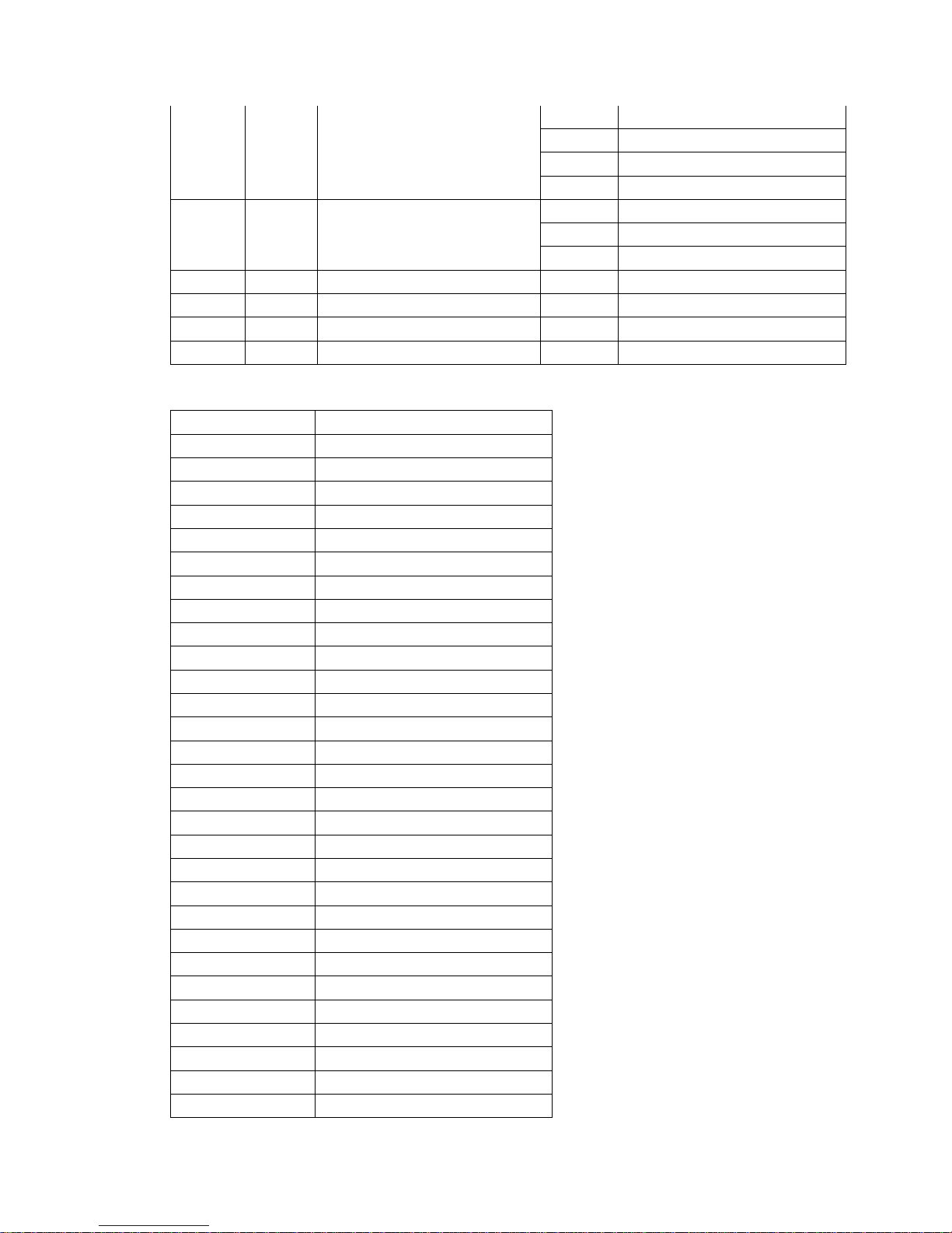
15 15 Reset
0-25 No valid
26-76 Effect motor reset
77-127 Pan /tilt reset
128-255 All reset
16 16 Blub control 0-9 No valid
10-100 Turn Off blub
101-255 Turn On blub
17 (channel20)pan/tiltspeed 0-255 Pan /tilt speed reduced
18 (channel20)color wheelspeed 0-255 Color wheel speed reduced
19 (channel20)dimmer prism speed
0-255 Dimmer prism speed reduced
20 (channel20)gobo wheelspeed 0-255 Gobo wheel speed reduced
Color wheelsheet
0-4 White
5-9 White +color1
10-14 color1
15-19 color1+color2
20-24 color2
25-29 color2+color3
30-34 color3
35-39 color3+color4
40-44 color4
45-49 color4+color5
50-54 color5
55-59 color5+color6
60-64 color6
65-69 color6+color7
70-74 color7
75-79 color7+color8
80-84 color8
85-89 color8+color9
90-94 color9
95-99 color9+color10
100-104 color10
105-109 color10+color11
110-114 color11
115-119 color11+color12
120-124 color12
125-129 color12+color13
130-134 color13
135-139 color13+color14
140-144 color14
145-149 color14+white
150-255 Color wheel rotate speed up
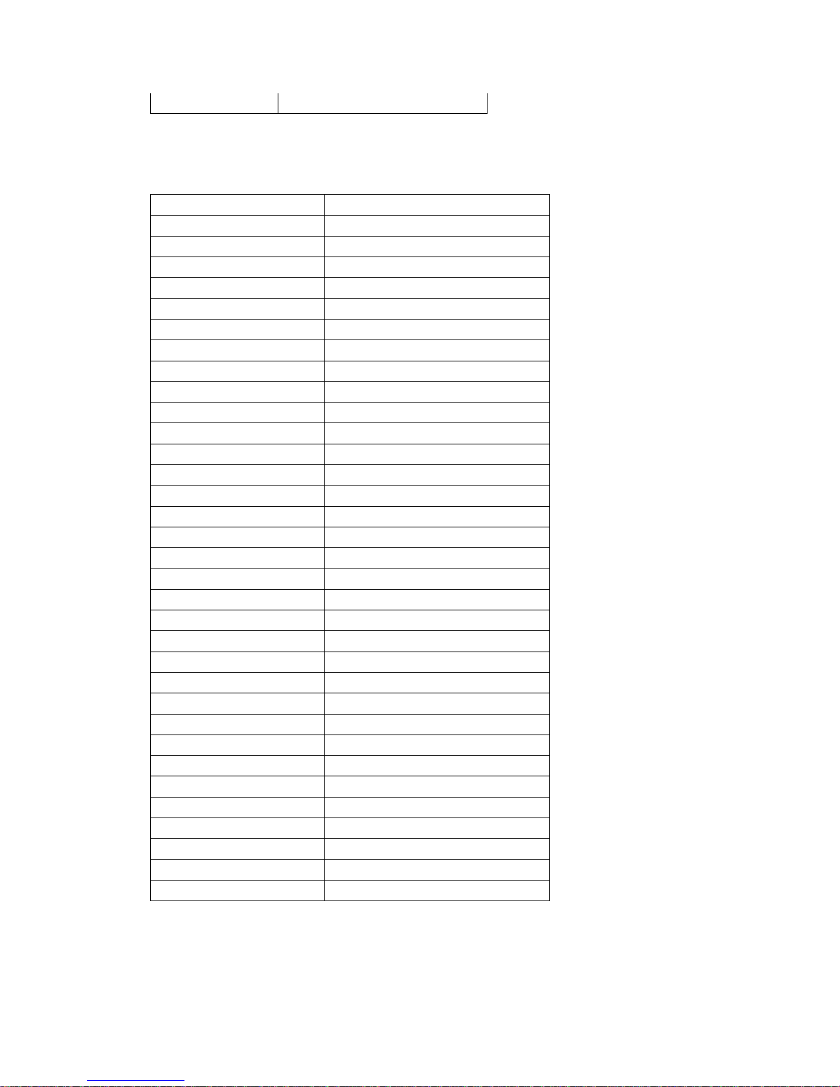
Gobo wheel sheet
0-4 Non
5-9 White
10-14 gobo2
15-19 gobo3
20-24 gobo4
25-29 gobo5
30-34 gobo6
35-39 gobo7
40-44 gobo8
45-49 gobo9
50-54 gobo10
55-59 gobo11
60-64 gobo12
65-69 gobo13
70-74 gobo14
75-79 gobo15
80-129 CW speed cut
130-134 NON
135-180 CCW rotate speed up
181-185 White shake
186-190 gobo2shake
191-195 gobo3shake
196-200 gobo4shake
201-205 gobo5shake
206-210 gobo6shake
211-215 gobo7shake
216-220 gobo8shake
221-225 gobo9shake
226-230 gobo10shake
231-235 gobo11shake
236-240 gobo12shake
241-245 gobo13shake
246-250 gobo14shake
251-255 gobo15shake

5.Technical specifications
Voltage AC100-240v 50/60Hz
Lamp source Yodn 2 RBulb
Color wheel 14colors+open
Gobo wheel 15 fixed gobos
Max temperature 104 F(40 C)
Data input/output 3pin XLR-connection、anode socket
Outside size 35CMx32CMx46.1CM
N.W 9.5kg
Table of contents
Other IMRELAX Lighting Equipment manuals


Popular Lighting Equipment manuals by other brands


Vision & Control
Vision & Control LDLF60x360-B470/UDC Instructions for use

B-K lighting
B-K lighting CORE DRILL installation instructions

Lightolier
Lightolier LSBW-2 Specification sheet

LED World
LED World KIT-LVHS-RGB-103-12V Important instructions

Chauvet
Chauvet Mini 4 Bar 2.0 user manual

Elation
Elation CUEPIX PANEL user manual