IMS APD 1-9 User manual

© Copyright 2014 IMS Company. All rights reserved. An ISO 9001:2008 Registered Quality Company
1
PORTABLE, DUAL
DESICCANT BED DRYERS
Model APD 1-9/HDP 1-9
INSTRUCTION MANUAL
Telephone: (440) 543-1615
Fax: (440) 543-1069
Email: sales@imscompany.com
Website: www.imscompany.com
December 2014
IMS Company
10373 Stafford Road
Chagrin Falls, OH 44023-5296


DRI-AIR INDUSTRIES, INC.
OPERATING MANUAL - APD 1-9, HPD 1-9 PORTABLE DRYERS
Revision 10/8/02 Page 3
CONTENTS
DRYER OPERATION/FEATURES---------------------------4
AIR FLOW SCHEMATIC FOR APD 1-9 DRYERS------- 6
AIR FLOW SCHEMATIC FOR HPD 1-9 DRYERS ------7
(HIGH PERFORMANCE MODEL SHOW)
DRYER CYCLE DIAGRAM ------------------------------------8
PLC STANDARD ELECTRICS -------------------------------9
INSTALLATION PROCEDURE ----------------------------- 10
Electrical Connection ------------------------------------- 10
Check for correct motor rotation ----------------------- 10
Compressed Air Connection---------------------------- 10
START-UP PROCEDURE ----------------------------------- 11
Standard Electrics----------------------------------------- 11
To Set Temperature: -------------------------------------- 11
Microprocessor Control ---------------------------------- 12
CLOSED LOOP LOADING SYSTEM --------------------- 13
ReceiverInstallation -------------------------------------- 13
Vacuum Check --------------------------------------------- 14
Adjustment of Sensors ----------------------------------- 14
Material Flow Adjustment-------------------------------- 15
BASIC TROUBLE SHOOTING for
CLOSED LOOP LOADING SYSTEM --------------------- 16
Material will not feed. ------------------------------------- 16
CLL MAINTENANCE------------------------------------------ 16
DailyMaintenance:---------------------------------------- 16
MonthlyMaintenance: ------------------------------------ 16
DRYER OPERATION-TROUBLE SHOOTING --------- 17
DRYER OPERATION-DETAILED DIAGNOSIS -------- 18
DRI-AIR ROTARY ZONE VALVE--------------------------- 19
PARTS LISTS
ARID-X 18 - 35 APD 1-4 and HPD 1-4--------------- 20
ARID-X 50 - 100 APD 5-9 and HPD 5-9 ------------- 21

DRI-AIR INDUSTRIES, INC.
OPERATING MANUAL - APD 1-9, HPD 1-9 PORTABLE DRYERS
Revision 10/8/02
Page 4
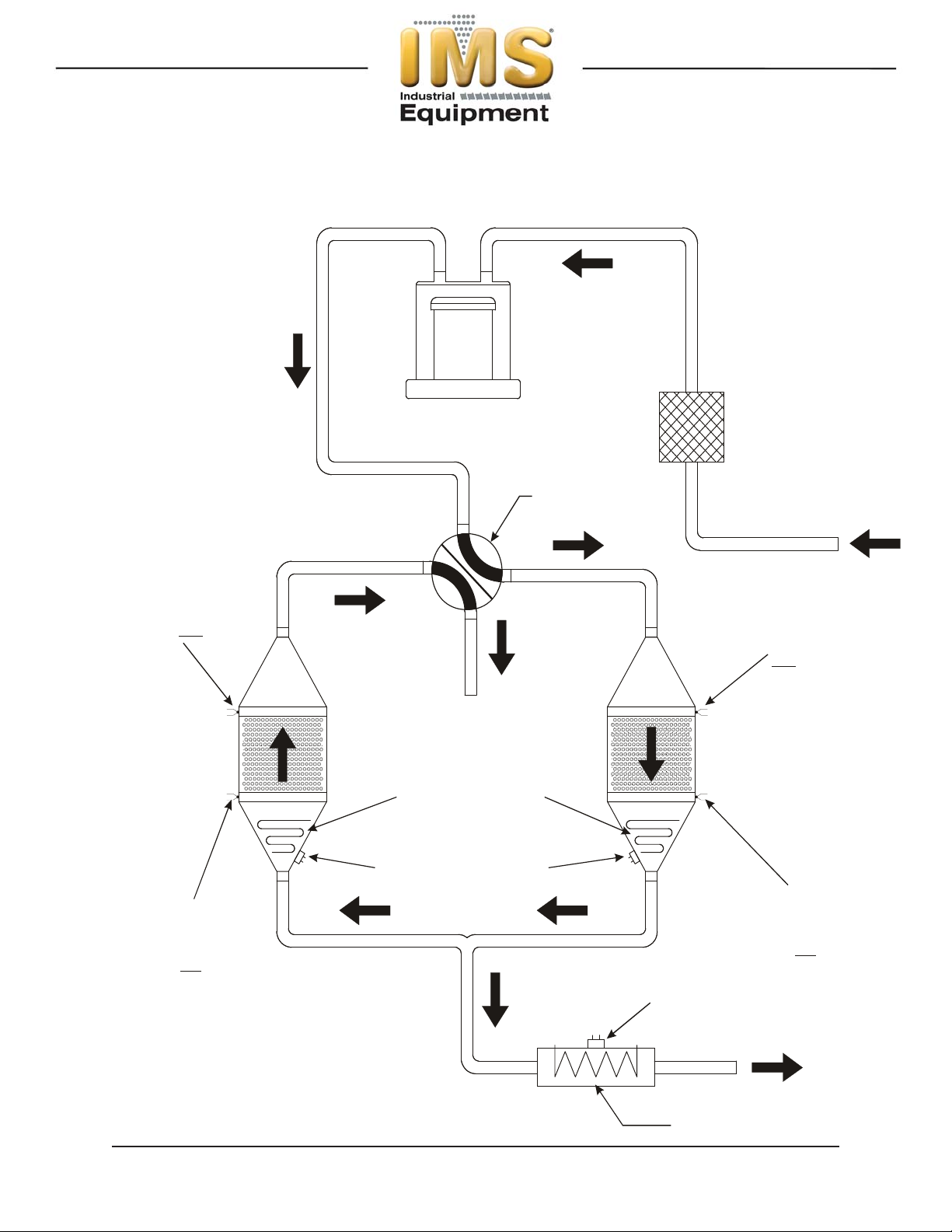
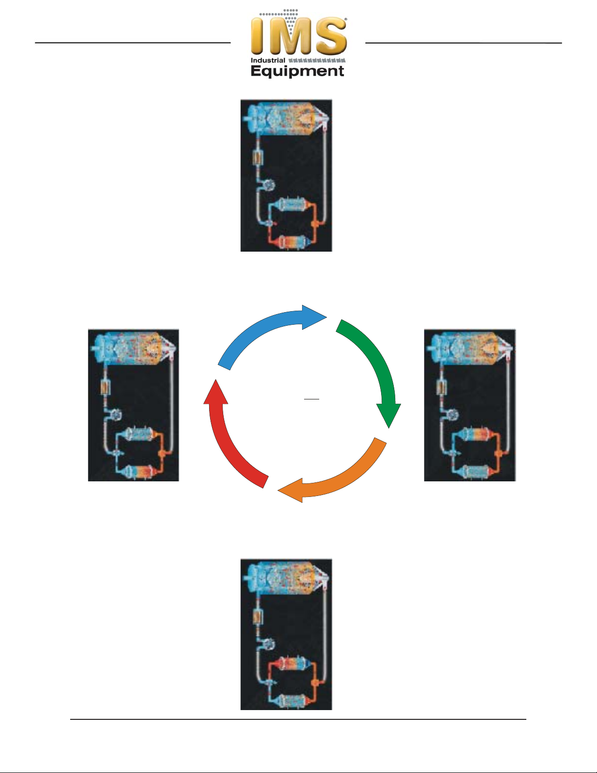
The ARID-X dryer series is a dual bed design that provides a
constant supply of dry air to the material hopper. While one
bed is removing moisture from the process air the other is
regenerating by heating the desiccant to a high temperature.
Once the regenerated bed cools down, the Zone Valve
switches the airflow, and the newly regenerated bed is used to
desiccate the process air stream. The saturated bed is now
regenerated in the same manner, completing the regeneration
cycle. The cycle is depicted Page 8.
The airflow design of the ARID-X dryers makes the
regeneration cycle more efficient because we utilize a small
amount of the desiccated process air rather than ambient air
to regenerate the desiccant bed. This reduces the impact of
the high moisture content of the ambient air, which would
contaminate the desiccant bed, and allows the dryer to attain
a lower dew point. Please see the Air Flow Schematic on
Page 6.
HP4-X Design
Our patented HP4-X design incorporates 4 desiccant beds
where two are stacked, one over the other. This nearly
doubles the amount of desiccant available for drying the
process air stream, and because of the tower design, the
dryer is able to regenerate the desiccant in the same time as
our ARID-X series. This allows the dryer to operate in very
high humidity conditions without affecting the process air dew
point. In fact, this design produces dew point levels of – 40’ to
-80’ C for faster more complete drying of your material. Please
see the Air FLow Diagram on Page 7.
Hopper Design
Dri-Air’s ”all stainless” hopper design utilizes a stainless steel
inner shell surrounded by a stainless steel jacketed insulation
layer. The easily removable stainless steel spreader cone
promotes proper material flow to ensure that the material is
dried efficiently and no dried material is left at the hopper
bottom that needs to be fed out prior to operating. You must
ensure that your hopper is adequately sized for your usage
rate and is kept filled, to ensure that you have sufficient time to
dry the material.
DRYER OPERATION/
FEATURES

DRI-AIR INDUSTRIES, INC.
OPERATING MANUAL - APD 1-9, HPD 1-9 PORTABLE DRYERS
Revision 10/8/02 Page 5
Closed Loop Loading System
Dri-Air’s closed loop loading system utilizes a dedicated
blower, small receiver, filtration system and desiccated air to
move the material from the dryer hopper to the molding
machine. This eliminates the possibility that your material will
be contaminated with moisture as with some other material
transfer systems, helping to eliminate defects resulting from
moisture contamination. Please refer to the Closed Loop
Loader System section of this manual for the proper
installation and maintenance.
Dryer Controls
The ARID-X series can be supplied with the standard PLC
Control Module or the advanced Microprocessor Control
Module, while the HP4-X series is only available with the
Microprocessor Control Module.
The PLC Control module includes a PLC control board,
display board, temperature controller and touch pad that is
programmed for the drying cycle described above. The
controller, display board and touch pad indicate the machine
status, alarms, set points and allow you to enter operational
settings for the dryer. These are explained in more detail later
in this manual.
The Microprocessor Control Module is one of the most
sophisticated yet operator friendly controls on the market. It
has many more features than the PLC control module that
provide the operator with more control and operational
flexibility with the dryer. These features and the operating
instructions are covered in detail in the Microprocessor
Control Instruction Manual included with your dryer.
DRYER OPERATION/
FEATURES (Cont.)

DRI-AIR INDUSTRIES, INC.
OPERATING MANUAL - APD 1-9, HPD 1-9 PORTABLE DRYERS
Revision 10/8/02
Page 6
AIR FLOW SCHEMATIC
FOR APD 1-9 DRYERS
XX
VORTEX BLOWER
4-WAY ZONE
VALVE
FILTER
VENT
SAFETY THERMAL
SAFETY THERMAL
REGENERATION
AND PROCESS
HEATER
TO HOPPER
PROCESS HEATER
(APD 5-9)
CONTROL
THERMOCOUPLE
H2
CONTROL
THERMOCOUPLE
L1
CONTROL
THERMOCOUPLE
L2
CONTROL
THERMOCOUPLE
H1

DRI-AIR INDUSTRIES, INC.
OPERATING MANUAL - APD 1-9, HPD 1-9 PORTABLE DRYERS
Revision 10/8/02 Page 7
AIR FLOW SCHEMATIC
FOR HPD 1-9 DRYERS
XX
VORTEX BLOWER
4-WAY ZONE
VALVE
FILTER
VENT
CONTROL
THERMOCOUPLE *
M2
CONTROL
THERMOCOUPLE *
M1
SAFETY THERMAL
SAFETY THERMAL
SAFETY THERMAL
REGENERATION
AND PROCESS
HEATER
REGENERATION
AND PROCESS
HEATER
TO HOPPER
PROCESS HEATER
(HPD 5-9)
SECONDARY
REGENERATION
HEATER
CONTROL
THERMOCOUPLE
H1
CONTROL
THERMOCOUPLE
H2
CONTROL
THERMOCOUPLE
L2
CONTROL
THERMOCOUPLE
L1
* - CONTROL THERMOCOUPLE
FOR PLC CONTROL ONLY

DRI-AIR INDUSTRIES, INC.
OPERATING MANUAL - APD 1-9, HPD 1-9 PORTABLE DRYERS
Revision 10/8/02
Page 8
Dryer Cycle
Diagram
Desicant Beds
Zo ne 1 He a ting
Zone 2 Cooling
Zo ne 2 He a ting
Zone 1 Cooling
Va lve Shifts
Valve Shifts
DRYER CYCLE
DIAGRAM
XX

DRI-AIR INDUSTRIES, INC.
OPERATING MANUAL - APD 1-9, HPD 1-9 PORTABLE DRYERS
Revision 10/8/02 Page 9
The control package includes a PLC controller which is
programmed for the drying cycle previously discussed. The
display board indicates the machine status, heater operation
and alarms. See section on start up for details.
Below are descriptions of the inputs and outputs of the PLC
which are used for trouble shooting. A lit LED indicates the
input or output is actuated. All inputs are 12 volts AC and all
outputs are 110 volts AC and 15 v DC to the heater relays.
Refer to the electrical schematic for more detail.
PLC STANDARD
ELECTRICS
XX
S2
J12
D16
C11
C20
C14
C15C13
D20
D15
D12
D10D14
D9D13
D8D11
J5
Jp7
J2
11
J118
J11
J11A
U7
U5
U9
U2
U2A
S1
R36
OSC1
OSC3
OSC2
Rn7
OSC1
R11
R12
R13
R14
+
+
+
++
C18
C13
C16
D16
C12
Rn5
Rn6
INPUTS
Rn7
OUTPUTS
R37
R38
Tb1
R1
R2
R3
R4
R5
R6
Jp1
Jp2
Jp3
Jp4
Jp6
Jp5
Br1+ +C18
C17
C22
C23
L1
L2
Z1
C2
R7
R8
C11 C0
C1
C2
C3
C2
U3
U4 U6
C8
U11
C15 D8
D9
D0 D1 D2 D3 D4 D5 D6 D7
D10
D11
D12
D13
D14
D15
C4
C5
C6
C7
C9
C19 J5
R2
OSC1
OSC3
OSC2
J2
U8
U9
U1
C1
0
1
2
3
5
6
7
4U2
Jp7
Rn4
Rn3
U5
U18
C14
Tb2
S
mal l
PLC03
REV E
8 UNUSED
8A UNUSED
9 UNUSED
9A UNUSED
10 ALARM (OPTIONAL)
11 HIGH TEMP. ALARM (OPTIONAL)
12 UNUSED
13 MAIN CONTACTOR/TEMP CONTROL
14 ZONE VALVE
PROCESS HEATER
ARID-X 50-100
Z1 TOP HEATER
Z2 TOP HEATER
TEMP
SAFETY
MAIN
HI TEMP
POWER
DISPLAY BOARD - P/N 83401
THERMOCOUPLE BOARD
MOTHER BOARD
PORT
DRI-AIR INDUSTRIES
EXPANDER BD REV C
SS4
AL2
CR1
M2
AL1
SS1
SS2
110 VAC
FROM XFORMER
T1
50
14
UNUSED
NON H.P.
50-300
#9TEMP.CONTSIGNAL
SAFETY
7DAYTIMER
HI TEMP. ALARM SIGNAL
UNUSED
UNUSED UNUSED
GROUND
L1
L2
QT9
QT8QT7QT6QT5
OL1
7DAYTIMER
H.P ONLY 50-100 PROCESS TUBE
C1
0
1
2
3
4
5
6
7
C13C14C15C16C17
Ch5 Ch4 Ch3 Ch2PWR Ch1 Ch0
C3 C4
U1 U10
C2
C21
TC rev B
Rgain
C20 C19
C18
C9
J2
JP2
JP3
DegC
X10
OSC1
JP1
ANALOG
TC
C8
J1
C7
C6
C1
C10 C11
C5
1
1
1
2
2
2
3
3
C12
-
+
-
+
-
+
-
+
-
+
-
+
-
+
H2
H1
M2
M1
L2
L1
UNUSED
SS3
SS5
-
+-
+-
+
+
+
-
-
Z1 BOTTOM HEATER
Z2 BOTTOM HEATER
UNUSED
UNUSED
50-300
NON H.P.
TC1
TC1
JUMP
UNUSED
8
9
10
11
P/N 84100

DRI-AIR INDUSTRIES, INC.
OPERATING MANUAL - APD 1-9, HPD 1-9 PORTABLE DRYERS
Revision 10/8/02
Page 10
For all Dri-Air models except ARID-X 10, AHM-1, & PDII
Electrical Connection:
Open electrical access door on the front of the machine by
turning the disconnect off and turning the lower clamping
screw 1/2 turn counterclockwise. Locate the disconnect by
following the operating handle down to the electrical panel.
Insert the incoming power cable or conduit through the hole
provided on the side of the machine.
«use approved wire and fastening means «
Wire incoming power to the top of the disconnect as shown in
the diagrams below.
NOTE:
When 3 wire supplies are used in place of 4 wire supplies,
a control transformer is required.
3 PHASE DRYER INSTALLATION
CHECK FOR CORRECT MOTOR ROTATION
BEFORE RUNNING DRYER
To check motor rotation.......
Leave the electrical cabinet door open so the blower can be
observed. Turn on the power to the dryer and press the ON/
START touch pad and then immediately press the OFF/STOP
touch pad. Observe the cooling fan on the top of the blower
motor and verify the fan is turning clockwise. If the motor is
not turning clockwise, switch any two adjacent supply wires.
Compressed Air Connection:
Compressed air is only required for dryers which have the
closed loop loader as part of the system. For those units:
CONNECT COMPRESSED AIR TO INLET ON FRAME
UNDER DRYER. The closed loop system includes a
regulator that is set to the proper pressure and an automatic
drain water separator. Maximum incoming pressure not to
exceed 145 psi (1.0 mpa).
The unit is now ready for operation.
INSTALLATION
PROCEDURE
XX

DRI-AIR INDUSTRIES, INC.
OPERATING MANUAL - APD 1-9, HPD 1-9 PORTABLE DRYERS
Revision 10/8/02 Page 11
Standard Electrics
Operating this unit is very simple. Once the dryer is
connected to the facility power supply, the unit can be started
by turning the disconnect located on the electrical panel
enclosure to the ON position and pressing the ON button on
the Control Panel Key Pad. To shut the dryer off, simply push
the OFF button on the Control Panel Key Pad and turn the
disconnect to the OFF position.
Setting the process air temperature is done using the Digital
Controller.
For a more detailed explanation, see the following sections.
Control Panel - Operating Display
Turn power on at dryer using disconnect.
1. POWER light indicates power to the unit is on.
Press ON button on key pad
2. Illuminated BLOWER Light indicates Blower is on.
3. Flashing ZONE light indicates bed is in
Regenerationcycle.
4. Steady ZONE light means bed is in cooling cycle.
5. Illuminated HEATER light indicates heater is on.
Alarm Conditions:
6. Flashing HIGH TEMP. ALARM indicates an over or
under temp alarm. Unit shuts down.
7. Steady HIGH TEMP. ALARM light indicates thermo-
couple has failed. Further diagnostics are required.
8. Flashing ALARM light indicates a safety override
condition has occured. Dryer shuts down.
Digital Controller - Setting Process Air Temperature:
Press SET button - temperature set display will flash.
Press up arrow to increase temperature and down arrow to
decrease temperature.
Press SET again to enter the new temperature.
If the display flashes, the temperature is out of the control
range.
If the display shows 0000 the thermocouple is not connected
or is faulty.
START-UP PROCEDURE
XX

DRI-AIR INDUSTRIES, INC.
OPERATING MANUAL - APD 1-9, HPD 1-9 PORTABLE DRYERS
Revision 10/8/02
Page 12
Microprocessor Control
1. Power light indicates there is power on.
2. After initializing, dri Air will be displayed.
3. Press START to start the dryer.
4. To set the temperature:
press SET - right display shows set temp
change setting using arrow keys
press ENTER to input new setting
5. Left display indicates actual temperature
6. Right display shows dewpoint or set temp
press TEMP D.POINT button to change
7. To set high temp alarm: (degrees over setting)
press ALARM - right display shows setting
change setting using arrow keys
press ENTER to input new setting
8. Status block indicates heater on or fault
9. See manual for setting 7-day timer .
10. Configuration of the dryer parameters is done
using the setup button. see manual.
For a more detailed explanation of the features and operation
of our Microprocessor Controller, please consult the
Microprocessor Operating manual enclosed with this unit.

DRI-AIR INDUSTRIES, INC.
OPERATING MANUAL - APD 1-9, HPD 1-9 PORTABLE DRYERS
Revision 10/8/02 Page 13
The closed loop loading system uses a separate vortex blower
to provide the vacuum and “pressure assist” necessary to
move the dried resin from the hopper take-off box to the
receiver mounted on the feed throat of the molding machine.
At the start of the loading sequence, the lower proximity switch
on the receiver senses there is no material. The blower starts,
and the loader valve on the inlet line to the blower is opened.
Because the receiver is sealed to the feed throat, a vacuum is
created within the take off box, pulling material from the
hopper.
The outlet of the blower ( pressure side) blows air into the take
off box to help move the material to the receiver and close the
air loop. When the upper proximity switch on the receiver
senses material, the blower is stopped and the loader valve is
closed to prevent anymore material from being conveyed and
left in the hose to possibly be contaminated with moisture.
To operate the system, complete the installation steps detailed
below and turn on the system by actuating the toggle switch
labeled LOADER on the front of the electrical panel enclosure.
If the Dual Closed Loop Loading option has been installed,
please consult the Dual Closed Loop Loader Operating Manual
enclosed with your dryer.
Prior to installing the receiver, you must inspect the surface of
the molding press feed throat that the receiver is being installed
upon to ensure that it is clean and flush. Surface irregularities
must be removed, or a gasket installed, so that there will be no
vacuum leaks between the receiver and feed throat after
installation.
IMPORTANT
If the molding machine is equipped with a slide gate, swing
arm, starve feeder, additive feeder, or feed throat vent, you
must ensure these are sealed, as the system may not work
properly. If it is impractical, or impossible to seal off the
aforementioned equipment, Dri Air Industries has a Flap Valve,
available for purchase, that will enable the loading system to
functionproperly.
To install the receiver, simply drill holes in the bottom flange of
the receiver to match the hole pattern on the molding press
feed throat and affix the receiver with bolts sufficient to
accommodate the operating stresses. A silicone gasket is
provided with the receiver to ensure a tight seal between the
receiver bottom and the feed throat. Connect the plug for the
upper proximity switch into the line labeled H and connect the
lower proximity switch plug into the line labeled L. Connect the
material feed hose and vacuum hose as shown in drawing
82222 in the appendix to this manual.
CLOSED LOOP
LOADING SYSTEM
RECEIVER
INSTALLATION

DRI-AIR INDUSTRIES, INC.
OPERATING MANUAL - APD 1-9, HPD 1-9 PORTABLE DRYERS
Revision 10/8/02
Page 14
Prior to production operation of the loading system, we strongly
recommend that you ensure the loading system is properly
sealed. To test the seal, follow the steps detailed below.
While the loader is running, close the hopper slide gate
and remove the material wand and attached hose from
the takeoff box. Check the vacuum level by placing
your hand over the wand. Return the wand to the take-
off box.
Remove the hose from the bottom port of the blowback
filter canister. Place your hand over the filter canister
port. Compare this vacuum level to the level observed
at the material wand. The two vacuum levels should be
the same.
Any difference between the vacuum levels is caused from
leaks in the loading system. Check for loose hoses, missing
gasket on the cyclone, or other possible sources of leaks
described below.
The most likely source is the seal between the feed throat and
receiver, or the configuration of the feed throat and material
feeder associated with the molding press. The presence of
vacuum leaks at these locations may exhibit the following
characteristics:
nMaterial in the receiver may be seen to bubble or
move when loading, as a leak at the feed throat causes
air to be drawn in at the bottom of the receiver rather
than from the take off box.
nPoor transfer of material from the take-off box to
the receiver.
nLarge amounts of material or dust being pulled
into the blowback filter cannister.
If any of these occurrences are observed, the steps to improve
the vacuum seal detailed in the previous section on Receiver
Installation will be required.
The proximity sensors supplied with the receiver may require
adjustment to operate properly. When positioning the sensors,
ensure that they are placed as close as possible to the outer
surface of the receiver as they operate by sensing the density
of the material in the receiver. Vertically position the lower
sensor to set the material level at which the load cycle will
initiate and the upper sensor to set the material level at which
the load cycle will stop. CAUTION: Do not overfill the
reciever as material may be drawn back into the blowback
filter canister.
PROXIMITY SENSOR
ADJUSTMENT
VACUUM CHECK

DRI-AIR INDUSTRIES, INC.
OPERATING MANUAL - APD 1-9, HPD 1-9 PORTABLE DRYERS
Revision 10/8/02 Page 15
To adjust the sensor’s sensitivity, turn the adjustment screw on
the back of the sensor. The adjustment screw turns a 20 turn
potentiometer with a clutch to prevent over adjustment. If you
are unsure as to the current setting of the sensor, turn the
screw 20 turns counterclockwise. The LED should light with
no material in front of the sensor. Turn the screw 4-6 turns
clockwise and proceed as directed below.
With no material in front of the sensor, the LED on the back of
the sensor should be lit. If not, turn the adjustment screw
located on the end of the sensor counterclockwise until the
LED turns on.
With material in front of the sensor, the LED on the back of the
sensor should be off. If not, turn the adjustment screw
clockwise, until it turns off.
Material flow to the receiver should be continuous and smooth.
Irregularities in flow rate and volume can be affected by the
position of the material wand inserted into the take-off box or
the density of the resin. To adjust the flow, take the steps
detailedbelow.
Upon initial operation of the loading system, push the wand in
until it stops. Then pull it out 1 to 2 inches and tighten the set
screw on the take-off box material outlet. Operate the loading
system and observe how the material flows into the receiver. If
the flow rate is not as desired, the wand can be adjusted out to
reduce the flow of material conveyed, or in, to increase the
amount. Typically, loading times are 5-6 seconds for a 2”
receiver and 15-20 seconds for the 4” receiver.
If the material flow is irregular, with “slugs” of resin being
delivered to the receiver, the wand is most likely pushed too far
into the take-off box. This “chokes” off the air flow required to
convey the material, causing the irregular flow. To remedy this
condition, pull the wand out slightly and the material will flow
more evenly and quickly.
If little or no material is conveyed and there are no blockages in
the take-off box or material hose the wand may be pulled too
far out of the take-off box. Push the wand in until you get the
desired flow rate.
MATERIAL FLOW
ADJUSTMENT

DRI-AIR INDUSTRIES, INC.
OPERATING MANUAL - APD 1-9, HPD 1-9 PORTABLE DRYERS
Revision 10/8/02
Page 16
Material will not feed.
1. Ensure the proximity sensors are adjusted and working
properly. Both sensors LED’s should be lit when the
receiver is empty. Check that the sensors are tightened
on the bracket and the cable connectors are tight and
correct.
2. Check system for leaks. Tighten hose clamps. Check
seal at receiver/feed throat interface by comparing
vacuum levels as directed in previous section on
ReceiverInstallation.
3. Ensure the blower operates. Check the electrical
system to see if the relay is working and that the blower
overload is not tripped. Trip window will be orange/yellow
if tripped. Check to see that the blower rotation is
correct (clockwise).
4. Ensure that the compressed air is connected to the
system and the pressure regulator is set to 60 psi. Does
the air valve open when the system calls for material?
The air line to the valve can be easily disconnected by
pushing in on the plastic sleeve and removing the hose.
The air line should be pressurized when the system is
loading.
5. Ensure the drain valve at the bottom of the filter is
closedproperly.
Daily Maintenance:
Clean filter when loader is not working.
The filter is cleaned automatically with an air blast at the start
of each loading cycle. The canister needs to be drained
periodically by opening the valve at the bottom of the canister.
Gently bang on the side of the cannister with your hand to
loosen any fines and close the valve.
Monthly Maintenance:
Clean filter sock by removing the quick clamp on the filter and
removing the top cover. Remove the bag assembly and blow
off with an air gun. Install bag assembly, top cover and quick
clamp checking that the seal is proper. This maintenance may
need to be performed more frequently if your material is dusty,
or less frequent if your material is clean. We strongly
recommend it be performed every 6 months regardless of
material conditions
Tighten all hoses and hose clamps and check for leaks.
BASIC TROUBLE
SHOOTING for
CLOSED LOOP
LOADING SYSTEM
CLOSED LOOP LOADER
MAINTENANCE

DRI-AIR INDUSTRIES, INC.
OPERATING MANUAL - APD 1-9, HPD 1-9 PORTABLE DRYERS
Revision 10/8/02 Page 17
The new Dri-Air Standard PLC and MICROPROCESSOR
Electrics were designed for quick diagnosis of problems.
The following steps should be done before proceeding with
other diagnostic steps.
1. Check the Power Circuit:
a. Incoming fuses or circuit breaker
b. All dryer fuses:
Each fuse, with the exception of the main fuses, has
a blown fuse indicator light that illuminates when the
fuse is blown.
c. Is power supplied to the unit?
d. Check heater continuity using a volt ohmmeter.
2. Compressed Air:
For those models that require compressed air.
a. Is compressed air connected with at least 60 PSI
b. Check water separator and drain if necessary
c. Pressure gage should read 60 PSI
3. Air Flow Circuit:
a. Ensure Zone Valve position corresponds to the
regeneration cycle by comparing the Zone position lights
on the Zone Valve to the ZONE position lights on the
dryerpanel.
b. Make sure that all hoses are connected, not crushed,
and free from obstructions.
c. Inspect filter and make sure cover is tight and the filter is
clean.
4. Control Circuit:
a. Using the PLC/MICRO Display Panel ZONE indicator
lights as a guide for the dryer regeneration cycle, check
that all inputs/outputs are proper for the part of the
regeneration cycle that the machine is in.
b. Monitor the PLC output lights to ensure the
corresponding LED on the power board is illuminated
and there is an output voltage to the heater.
5. Operating Conditions:
a. Check the process temperature. It should not be set
below 140° F (60° C) because the unit will go into high
temp alarm.
DRYER OPERATION
TROUBLE SHOOTING

DRI-AIR INDUSTRIES, INC.
OPERATING MANUAL - APD 1-9, HPD 1-9 PORTABLE DRYERS
Revision 10/8/02
Page 18
Machine will not start: Power light is not on.
1. Check circuit breakers (CB1) or incoming fuses inside
control box to see if they are tripped or blown. Reset
circuit breakers by turning them off and then on.
2. Check small fuses (FU1 & FU2) next to contactor. The
LED will be lit if they are blown. Replace if necessary by
opening the fuse holder and put new fuse into holder.
3. Check that incoming power to the unit is proper.
4. Check safety snap discs.
Alarm light is flashing: Unit will not run.
Main contactor is not pulling in.
1. Check the motor overload OL1 located in the panel. If it
is tripped, the window will show as orange/yellow. Reset
overload by pushing in the reset button.
Machine will not run: High Temp Alarm Light flashing.
This indicates that the temperature has exceeded the high
limit programmed into the temperature control or the set
temperature can not be reached.
Press stop and restart machine holding in the start button.
Monitor the actual temperature to see if it exceeds the set
point or can not reach the set point. If it can not reach set
point, see section below.
Machine will not run: High Temperature Alarm Light on, not
flashing:
1. This indicates an “open” thermocouple or the
temperature in the desiccant tower exceeded 900° F.
Machine will not reach temperature:
1. If the process heater light is not lit.
A.Check output from temperature controller and input to
PLC.
B.Check the thermocouple. The tip should be in the
middle of the hose.
2. If the process heater light is lit.
A.Check fuses on power board
B.Check solid state relays on power board.
C.Check that the air flow is not obstructed.
D.Check blower rotation
E.Check heater for continuity.
Check the limit first by pressing the SET button on the
temperature control and holding until AL is displayed. The
setting shown indicated the amount over set point that the
alarm will be actuated. It is factory set to 50°F (30°C) and
should not be set below 30°F (16°C) or it will actuate too soon.
DRYER OPERATION
DETAILED DIAGNOSIS
(PLC Controlled Dryer)
For MicroControlled dryers please see the
Microprocessor Control Instruction Manual

DRI-AIR INDUSTRIES, INC.
OPERATING MANUAL - APD 1-9, HPD 1-9 PORTABLE DRYERS
Revision 10/8/02 Page 19
If the temp exceeds the set point check the following:
1. Remove the hose from the top of the hopper to check air
flow. There should be air flow out of the hopper with a
suction on the hose. If there is little or no flow, check the
inlet hose.
2. Inspect the filter to make sure that it is clean and not
affecting the air flow.
3. Check the power boards to see if one of the solid state
relays has failed on. Using an ammeter or voltmeter on
the output to the heater, see if there is power when the
LED is not lit which will indicate a failed relay.
4. Check the valve position.
The Dri-Air rotary valve is designed to provide very little flow
restriction and no leakage. It incorporates high temperature,
self adjusting seals for years of trouble free service. The
electrical controls are built into the end of the valve and
include position lights.
Trouble shooting is easy. If the lights indicating position do not
match the zone displayed on the control panel, or there are no
lights, the valve is not working properly. See if the cam is
actuating a switch.
DO NOT PUT FINGERS INTO VALVE WITH POWER ON
Check all electrical connections to make sure they are tight.
Contact factory with the serial number of the dryer for a
replacement valve.
DRI-AIR
ROTARY ZONE VALVE

DRI-AIR INDUSTRIES, INC.
OPERATING MANUAL - APD 1-9, HPD 1-9 PORTABLE DRYERS
Revision 10/8/02
Page 20
APD 1-4 and , HPD-1-4
DESCRIPTION APD HPD
Dryer Filter Element 81055 81055
Zone Valve 83705 83705
Thermocouple (Process) 82174 82174
Desiccant 80082 (Lbs/Machine) 8 lbs. 14 lbs.
Tower Clamp 81017 81017
Tower Gasket 81028 81028
RegenerationValve NR NR
Pressure Switch NR NR
Regulator NR NR
MAC Valve NR NR
Caster (Swivel) 81799 81799
Caster (Fixed) 81798 81798
Filter Element 82389 82389
Blowback Valve 82695 82695
Proximity Switch (K10203 Std. El.) 81180 81180
Proximity Switch (K15208 Micro) 82298 82298
Regulator 82995 82995
Air Valve (SMC) 84220 84220
Load Valve 84229 84229
STD MICRO
Disconnect 82308 82308
Temperature Control (RKC CB-100) 84016 NR
Main Board 84100 82071
DisplayBoard 83401 82072
Thermocouple Board 84049 NR
Transformer 83437 84131
Current Transformer NR 82246
Main Contactor 82270 82270
Solid State Relay 82302 82302
IEC Contactor 80576 80576
IEC Contactor * 84860 84860
Power Board 83493 83493
Power Board (208 & 230 v Dryers) 84080 84080
Single Pole Relay 82496 82496
Double Pole Relay 80587 80587
Dual Solid State Board NR 82870
Toggle Switch 80466 80466
Safety Thermal Switch (Tower) 80221 80221
Thermocouple (Tower) 82174 82174
TRI-Solid State Board NR 83468
Dewpoint Sensor 81908 81908
Solid State Timer (Blowback) 83318 83318
Solid State Timer (Cleanout) 83527 83527
Solid State Timer (Auger Delay) 83442 83442
208V 230V 400V 480V 575V
Regeneration (Cone Style) 83342 83373 83982 83374 84235
HP Center (Flat Style) 82373 82373 83958 82505 84260
Process NR NR NR NR NR
PARTS LISTS
GENERAL
CLOSED LOOP LOADER
ELECTRICAL
HEATERS
NOTE:
TO ORDER BLOWERS OR
OVERLOAD REFER TO
PART NUMBER ON ITEM.
*:
IEC CONTACTOR USED IN ALL
FM, PD & HM DRYERS AND CLL
POWER PACKS WITH SERIAL
NUMBERS GREATER THAN
D14650
This manual suits for next models
1
Popular Dryer manuals by other brands

Whirlpool
Whirlpool WED4985EW installation instructions

Siemens
Siemens WT43H07CDN Installation and operating instructions

Frigidaire
Frigidaire GLEQ642CAS2 Wiring diagram

AEG
AEG LAVATHERM T8DEE845R user manual

Beko
Beko DRX827WN user manual

Zanussi Electrolux
Zanussi Electrolux TCE 7124 W Instruction booklet

GE
GE 234D1157P002 owner's manual

Siemens
Siemens WT45H2B8DN Installation and operating instructions

Heinner
Heinner HCD-V704B manual

Bosch
Bosch Vision 300 Series Operating, care and installation instructions

Zanussi
Zanussi ED 207 Instructions for the use and care

Frigidaire
Frigidaire FEQ1442CE Factory parts catalog